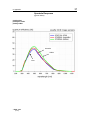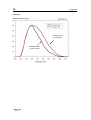
1
pixelfly
pixelfly qe
Operating Instructions
pco.
imaging
3
Safety Instructions
Safety Instructions
For your own safety and in order to guarantee a safe operation
of the camera, please read carefully the following information
prior to using the device.
• Never operate the camera at places where water or dust
might penetrate.
• Place the camera on a sufficiently stable basis.
Shocks like e.g. dropping the camera onto the floor, might
cause serious damage to the device. Therefore exclusively
the tripod attachment at the bottom side should be used for
mounting the camera.
• The camera is not be qualified for X-Ray applications and
can be damaged. Our warranty does not cover damaged
cameras caused by X-Ray applications.
• For applications with laser or plasma light please note that
the CCD sensor can be destroyed thermically or physically
with too much laser energy. Single pixels or the readout register and therefore the complete sensor can be destroyed.
The warranty does not cover damaged sensors by too much
laser light / laser energy.
• Always unplug the camera before cleaning it. Do not use
cleaning liquids or sprays. Instead, use a dry, soft duster.
• Never insert any objects through the device's slots. The applied voltage inside the camera can cause short-circuits or
electrical shocks.
• The slots in the camera housing are needed for ventilation.
In order to guarantee a proper operation and to prevent
overheating of the camera, these slots must always be kept
free.
• Make sure that the connecting cable is in good condition and
that the link to the socket does not represent an obstacle.
• Detach the camera and contact the customer service in the
following cases:
− When cable or plug are damaged or worn-out.
− When water or other liquids have soaked into the device.
− When the device is not properly working although you followed all instructions of the user's manual.
− When the camera fell to the floor or the housing has been
damaged.
− When the device shows apparent deviations of normal
operation.
©PCO 2006
pixelfly
5
Contents
Contents
1. Installation and Powering Up
1.1
Computer ...............................................................................7
System Requirements .............................................................7
Graphic Setup .........................................................................7
Installing the PCI-Board ..........................................................8
1.2
Installation of the Hardware Driver......................................9
Installation under Windows 9x/ME/2000/XP ...........................9
Installation under Windows NT................................................9
Installation under Linux ...........................................................9
1.3
Installation of the Software ‚CamWare’.............................10
1.4
Camera and PCI-Board .......................................................11
Serial Data Transfer ..............................................................11
Lens Mount............................................................................12
Filter Installation ....................................................................12
1.5
Powering Up ........................................................................12
2.
Functional Principle
2.1
2.2
2.3
Block Diagram and Internal Data Stream..............................13
Color Definition Algorithm......................................................16
Operating several Cameras from one Computer ..................17
3.
Timing
3.1
pixelfly VGA / HiRes / Scientific r.......................................18
Async Mode...........................................................................18
Video Mode ...........................................................................19
DoubleShutter Mode .............................................................20
pixelfly qe .............................................................................21
Async Mode...........................................................................21
Video Modee .........................................................................22
DoubleShutter Mod ...............................................................23
3.2
4.
Trigger Control
Internal Triggering .................................................................24
External Triggering ................................................................24
LED on the PCI-Board...........................................................25
©PCO 2006
pixelfly
6
Contents
5.
Front-End Processor
Front-End Processor .............................................................26
6.
Software
Application Software CamWare ............................................27
Plug-Ins .................................................................................27
Software Development Kit (SDK) ..........................................27
Drivers ...................................................................................27
7.
Servicing, Maintenance and Cleaning
Instructions
Servicing, Maintenance and Cleaning Instructions ...............28
Cleaning Method for the Optical Part ....................................28
8.
Appendix
Customer Service..................................................................29
Warranty................................................................................29
CE-Certification .....................................................................29
Dimensions and Weight (VGA, SVGA – long version) ..........30
Dimensions and Weight (QE – long version) ........................32
Dimensions and Weight (VGA, QE – short version)..............34
System Data..........................................................................36
Spectral Response ................................................................37
Operating Instructions pixelfly
Version 03/2006
Subject to change without prior notice!
Copyright by PCO, 2006
©PCO 2006
pixelfly
7
1. Installation and Powering Up
1. Installation and Powering Up
The pixelfly imaging system consists of camera and PCI-Board.
To get the system working properly, follow the instructions.
1.1 Computer
System Requirements
The PCI-Board should be installed in a computer with following
characteristics:
•
•
•
•
PCI-Bus with PCI-Chip Version 2.1 or higher
Intel Processor, Pentium or AMD
128 MB RAM
Possible Operating Systems
• Microsoft Windows 95 Version 4.00.950b or higher
• Microsoft Windows 98 or 98SE
• Windows ME
• Microsoft Windows NT 4.0 Workstation
• Microsoft Windows 2000 Workstation
• Microsoft XP
• Linux Kernel 2.2, preferable SuSE 6.3 or newer
In case of working with Linux, please contact PCO.
Graphic Board
For best display of images on the monitor we recommend the
use of highest performance boards with at least 4MB RAM,
preferable with AGP Bus architecture.
Graphic Setup
The camera generates 12 Bit (4096 grey levels). For display on
the PC Monitor 8 Bit (256 grey levels) respectively 3x8 Bit in
true color (16,7 millions colors) are generated.
In general, several graphic setups are possible. We recommend the setting with 24 or 32 Bit with 16.7 million colors.
In the 256-Color-Modus twenty colors are used by Windows for
internal purposes. This modus allows to display a maximum of
236 grey levels. Therefore only 7 bit (128 grey levels) are used
for black/white display.
Some graphic boards use in principle 6 bit for the 256-ColorModus, i. e. not more than 64 grey levels can be displayed on
the monitor.
©PCO 2006
pixelfly
8
1. Installation and Powering Up
Installing the PCI-Board
Caution!
Before touching the PCI-Board make sure you have not accumulated static charges. A discharge may destroy the sensitive
electronics and voids any guarantee.
Insert the PCI-Board in a free PCI-slot of your computer and
screw the bow onto the PC housing.
Make sure the board does not touch any electrical conducting
parts (housing, other boards, wires or chillers)
It is essential to use a master PCI-slot. Some computers require additional enabling of PCI-slot mastering on BIOS level.
©PCO 2006
pixelfly
9
1. Installation and Powering Up
1.2 Installation of the Hardware Driver
You can operate the camera with Windows9x/ME/2000/NT or
Linux.
Installation under Windows 9x/ME/2000/XP
New-Installation of the hardware driver
If you have Windows9x/ME/2000/XP installed, the computer
should automatically recognize the new hardware (PCI-Board)
and request you to insert a disk with the manufacturer's drivers.
For installation please read the actual information in the readme.txt file on the enclosed CD.
Updating the hardware driver
For updating an existing driver, please download the newest
driver version from the internet under http://www.pco.de.
For installation please read the actual information in the readme.txt file which will be download automatically with the
driver.
In case the downloaded drivers are compressed you have to
decompress them with a suitable program (e.g. ZIP program).
Installation under Windows NT
Installation of the Hardware Driver
If you install the camera under Windows NT, you need the
rights of the administrator. Please login as administrator.
For installation please read the actual information in the readme.txt file on the enclosed CD or after downloading from
internet.
Installation under Linux
The Linux driver is on the enclosed CD or can be downloaded
from internet under http://www.pco.de.
In case the downloaded drivers are compressed you have to
decompress them with a suitable program (e.g. ZIP program,
TAR program).
Detailed instructions for installation you will find in the readme
file.
©PCO 2006
pixelfly
10
1. Installation and Powering Up
1.3 Installation of the Software „CamWare“
CamWare is a 32 Bit Windows application. With CamWare all
camera parameters can be set. The images can be displayed
on the monitor and saved on hard disk. For detailed information
please see the separate manual ‚CamWare’.
You will find the software CamWare on the enclosed CD. The
newest version can also be downloaded from the internet under
http://www.pco.de.
Installation from CD
In case the CD will not start automatically, please start it manually by double click starter.exe.
Please select your camera and the software ‘CamWare’:
Installation from Internet
Download CamWare from the Internet to a free selected directory. The downloaded file must be decompressed with a suitable program (e.g. ZIP program) Start the installation with
setup.exe.
The newest information how to install CamWare can be found
in the readme.txt file.
To install CamWare under Windows 2000, Windows NT or
Windows XP you need administration rights.
Remark
After successful installation the computer has to be restarted.
The installation program transfers all necessary DLL and OLE
files to the respective Windows, checking automatically for existing older versions and replacing them by new ones.
Windows’95 carries out all „registry“-entries.
If the program is to be deleted from the computer, a proper deinstallation is carried out in
START - SETUP - SYSTEM CONTROL - SOFTWARE
After successful installation you will have the new directory
‘Digital Camera Toolbox’. CamWare and some additional useful
tools will be installed to this directory.
Hotline
©PCO 2006
pixelfly
In case you have problems during installation, call our hotline
(see „Customer Service“).
11
1. Installation and Powering Up
1.4 Camera and PCI-Board
Before Powering Up, make the connection between camera
head and PCI-Board.
In case of not using the enclosed cable, please note:
• Pleas use only Ethernet cables, where all 8 lines are connected (4x twisted pair).
• The cable quality must be at least category 5, 5+ or higher
• minimum cable length: 2m
• maximum cable length: 12.5m
Remark
The connectors and cable are identical with Ethernet cables but
there is no Ethernet protocol!
Standard and Compact PCI-Board
The front plates and connectors of the Standard and Compact
PCI-Boards are identical.
Frontplatten und Steckeranordnungen.
Interface 2 is the connection between camera head and PCIBoard.
The camera can be controlled via Interface 1 (e.g. external triggering, Front-End Processor, ...)
The LEDs show the operating states as follows:
LED 1 (green)
LED 1 (red)
LED 2 (green)
LED 2 (red)
©PCO 2006
pixelfly
control display when connection between camera head and
PCI-Board is ok
control display at data transfer
Power-On (blinking)
control display at external trigger input
12
Lens Mount
1. Installation and Powering Up
pixelfly has a standard C-Mount with a back focal length of
17.52mm (Distance between front edge of C-Mount and CCDsensor).
Standard C-Mount lenses or other lenses with their respective
C-Mount adapter (e.g. photo camera lenses) can be used. The
maximum screw-in depth of a lens (or adapter) is 9.5mm.
Deeper screwing in could destroy the protecting window of the
camera (no warranty!).
The VGA and HiRes sensors have a 1/2“ format, the SVGA and
QE sensors a 2/3“. We recommend to use for all pixelfly Versions a 2/3“ or 1“ compatible lens. Cameras with high resolution
sensor should preferably be equipped with a high quality lens to
take advantage of the high resolution.
The cameras can be equipped optionally with a filter. This filter
will be placed at the C-Mount ring. In this case the maximum
screw-in depth is only 6mm instead of the 9.5mm.
Insert Filters
Filters can be set in front of the CCD. You have to use a 24 mm
diameter filter.
In the C-mount screw there is a ring which can be screwed out.
Now the filter can be placed and the ring must be screwed in
again.
1.5 Powering Up
Check the following points:
• PCI-Board properly mounted
• Connection between camera and PCI-Board
• Lens mounted
Now start the program „CamWare“ from the directory
Programme – Digital Camera ToolBox.
For detailed information to CamWare please see the separate
manual ‚CamWare’.
©PCO 2006
pixelfly
13
2. Functional Principle
2. Functional Principle
The images, captured by the camera head, will be transferred
via a high speed data transfer to the PCI-Board in the computer. The data will be saved in the RAM of the computer where
the operator can decide what to do with them.
With the enclosed software ‚CamWare’ the camera can be controlled within the windows environment and the images can be
displayed on the monitor.
The Recorder function allows you to record image sequences
and display them as "movies".
The maximum memory space for the recorded images depends
solely on the RAM size of your computer.
When starting the program, the software automatically recognizes the camera type.
For detailed information to CamWare please see the separate
manual ‚CamWare’.
2.1 Block Diagram and Data Stream
Block Diagram
In the following block diagram the structure of the complete
camera system is shown.
Lens
CCD
High speed data transfer
CCD Head
PCI-Interface-Board
External Trigger Input
©PCO 2006
pixelfly
14
2. Functional Principle
Internal Data Stream of black/white cameras
The PCI-Board gets the 12bit data from the camera and transfers it via PCI-Bus to a 16bit array (of the PC Memory). The
higher 4bits are set to zero. The 16bit data are automatically
converted in a 8bit array and accessed by the graphic board.
Depending on graphic board setup display on the monitor is effected in 8, 24 or 32 bit.
File Formats
The command ‘Export’ stores 16bit or 8bit data on hard disk in
B16, TIFF, FITS, BMP, or ASCII format.
For further information see Chapter 2.3.
Display
The camera which acquires always 12 bit images resolves with
4096 (2E12) grey levels between black and white, however the
monitor display of the image is always limited to 8 bit and therefore to 256 (2E8) grey levels.
The command ‘Convert Control’ allows to select a discretionary
range between 0 ... 4095 grey levels which is then displayed in
256 grey levels on the PC monitor.
PC
Monitor
Camera
PCI-Interface-Board
Graphic Board
PCI-Bus
©PCO 2006
pixelfly
15
2. Functional Principle
Internal Data Stream of color cameras
The PCI-Board gets the 12bit data from the camera and transfers it via PCI-Bus to a 16bit array (of the PC memory). The
higher 4bits are set to zero. The 16 bit data are converted
automatically into a 3 x 8 bit array and accessed by the graphic
board. We recommend to display it in 32bits on the monitor.
File Formats
The command ‘Export’ stores 16bit or 8bit data on hard disk in
B16, TIFF, FITS, BMP, or ASCII format.
For further information see Chapter 2.3.
Display
The camera which acquires always 12 bit images resolves with
4096 (2E12) grey levels between black and white, however the
monitor display of the image is always limited to 8 bit and therefore to 256 (2E8) grey levels.
The command ‘Convert Control’ allows to select a discretionary
range between 0 ... 4095 grey levels which is then displayed in
256 grey levels on the PC monitor.
PC
Monitor
Camera
PCI-Interface-Board
Graphic Board
PCI-Bus
©PCO 2006
pixelfly
16
2. Functional Principle
2.2 Color Definition Algorithm
Color sensors with RGB filter for the colors red, green and blue
are used for the color cameras. The CCD sensor records for
each pixel the light information as grey level with 12 Bit dynamic
(RX, GX, BX).
With the help of the camera control software, for each pixel the
12 Bit data is converted by interpolating into a 8 Bit triplet (PRED,
PGREEN, PBLUE).
For this interpolation following algorithm is applied:
Algorithm 1
This algorithm optimises the color resolution.
A red, green and blue part of the color for virtual pixels will be
calculated. These virtual pixels are placed between the original
pixels. In CamWare this algorithm is also called as ‘Smooth’.
• The first pixel on the top left side is always "red".
• Between the physical pixels, there are virtual pixels PX which
are computed with the algorithm described below.
Physical Pixel
R1
G2
R3
G4
G5
B6
G7
B8
R9
PX
G10 R11
G12
G13
B14
B16
G15
...
Virtual Pixel
...
Conversion algorithm for the new pixel PX:
PRED
= ( 9 R11 + 3 R3 + 3 R9 + R1 )/16
PGREEN = ( G7 + G10 )/2
PBLUE = ( 9 B6 + 3 B8 + 3 B14 + B16 )/16
Algorithm 2
This algorithm optimises the spatial resolution. For each physical pixel, a color value (red, green and blue) is calculated, related to the corresponding neighbour pixel.
Example for Pixel6
PRED
= ( R1 + R3 + R9 + R11 )/4
PGREEN = ( G2 + G5 + G7 + G10 )/4
PBLUE = B6
Example for Pixel7
PRED
= ( R3 + R11 )/2
PGREEN = G7
PBLUE = ( B6 + B8 )/2
©PCO 2006
pixelfly
17
2. Functional Principle
2.3 Operating several Cameras from one
Computer
Depending of the computer specification up to four cameras
can be used in one computer at the same time.
On the PCI-Board there is a FIFO memory (no full frame memory!). The incoming data must be transferred in real time to the
computer RAM.
With the 16 MHz versions (VGA 640 x 480 pixel and HiRes
1360 x 1024) the data transfer is 32 MB/s. For two cameras in
one computer you have 64 MB/s.
With the 20 MHz version (Scientific 1280 x 1024 pixel and QE
1392 x 1024) the data transfer is 40 MB/s, with two cameras 80
MB/s.
Please note that with synchronous triggering, maximum two
VGA cameras can be used. Cameras with higher resolution
(pixelfly Scientific, HiRes, qe) can cause conflicts.
The advantage of the FIFO memory (compared with a full frame
memory) is that you have no additional delay.
The disadvantage, that only two PCI-Boards can be used in one
computer at the same time, can be avoided by using CompactPCI CPUs in several computers which are connected by 100
MBit Ethernet cable.
©PCO 2006
pixelfly
18
3. Timing
3. Timing
3.1 pixelfly VGA / HiRes / Scientific
The pixelfly timing depends of the exposure mode
Async-, Video- and DoubleShutter modes are available.
Async Mode
Each trigger (internal or external) generates an image.
The following signals /BUSY, /CCD-Exposure and /CCDReadout are at the 26-pin. HD-DSUB socket of the PCI-Board.
External Trigger
/ BUSY
/ CCD-Exposure
/ CCD-Readout
Internal
Delay
tdi
texp
tj1
tj2
Exposure
Time
CCD Readout Time
timing not scaled
10...20µs
5µs...65ms
0...5µs
300...700µs
Example for a external triggered sequence
/ BUSY
/ CCD-Exposure
/ CCD-Readout
CCD Readout Time
The CCD readout time depends of the CCD sensor (VGA, Scientifi, HiRes or UV) and of the selected binning:
VGA (200/205)
VGA (210/215)
Scientific
HiRes / UV
©PCO 2006
pixelfly
V1-Binning:
V2-Binning
V4-Binning
V1-Binning:
V2-Binning
V4-Binning
V1-Binning
V2-Binning
V1-Binning
V2-Binning
19,8ms ± 0,5
10,3ms ± 0,5
5,6ms ± 0,5
24,8ms ± 0,5
12,8ms ± 0,5
6,8ms ± 0,5
79,8ms ± 0,5
40,3ms ± 0,5
104,0ms ± 0,5
52,5ms ± 0,5
19
3. Timing
Video Mode
A trigger generates a complete imaging sequence.
The following signals /BUSY, /CCD-Exposure and /CCDReadout are at the 26-pin. HD-DSUB socket of the PCI-Board.
External Trigger
/ BUSY
/ CCD-Exposure
/ CCD-Readout
Intrinsic + System
Delay
Exposure Time < Readout Time
BUSY
CCD-Exposure
CCD-Readout
Exposure Time > Readout Time
BUSY
CCD-Exposure
CCD-Readout
CCD Readout Time
The CCD readout time depends of the CCD sensor (VGA, Scientifi, HiRes or UV) and of the selected binning:
VGA (200/205)
VGA (210/215)
Scientific
HiRes / UV
©PCO 2006
pixelfly
V1-Binning:
V2-Binning
V4-Binning
V1-Binning:
V2-Binning
V4-Binning
V1-Binning
V2-Binning
V1-Binning
V2-Binning
19,8ms ± 0,5
10,3ms ± 0,5
5,6ms ± 0,5
24,8ms ± 0,5
12,8ms ± 0,5
6,8ms ± 0,5
79,8ms ± 0,5
40,3ms ± 0,5
104,0ms ± 0,5
52,5ms ± 0,5
20
3. Timing
DoubleShutter Mode (only XD-Version)
Two separated full frame images with a short interframing time
can be captured. The length of the first exposure time will be
done by software input, the triggering either internally by software or by an external trigger signal. The exposure time of the
second image corresponds to the readout time of the first image. It depends of the used CCD sensor and binning mode.
During the interframing time td (dead time) no exposure should
be done
The following signals /BUSY, /CCD-Exposure and /CCDReadout are at the 26-pin. HD-DSUB socket of the PCI-Board.
External Trigger
/ BUSY
/ CCD-Exposure
/ CCD-Readout
Internal
Delay
Exposure
Image 1
Exposure
Image 2
Readout Time 1
Real exposure
on CCD sensor
tdi
texp1
tj1
tj2
tj3
td
Image 1
Readout Time 2
Image 2
10...20µs
5µs...65ms
0...5µs
300...700µs
0...3µs
2µs
timing not scaled
texp1 can be set to 10µs...10ms by software.
exposure time of image 2 (texp2) = readout time of image 1
Example
To set two laser pulses in a short time one after another (about
10µs), the following relation is valid. The timing of the first laser
pulse starts with the falling edge of /BUSY (respect. /CCDExposure). The first laser pulse must be set at the end of image
1, the second laser pulse at the beginning of image 2.
1. laser pulse = texp1 – tj1
2. laser pulse = 1. laser pulse + tj1 + (td + tj3 )
CCD Readout Time
The CCD readout time depends of the CCD sensor (VGA, Scientifi, HiRes or UV) and of the selected binning:
VGA (200/205)
VGA (210/215)
Scientific
HiRes / UV
©PCO 2006
pixelfly
V1-Binning:
V2-Binning
V4-Binning
V1-Binning:
V2-Binning
V4-Binning
V1-Binning
V2-Binning
V1-Binning
V2-Binning
19,8ms ± 0,5
10,3ms ± 0,5
5,6ms ± 0,5
24,8ms ± 0,5
12,8ms ± 0,5
6,8ms ± 0,5
79,8ms ± 0,5
40,3ms ± 0,5
104,0ms ± 0,5
52,5ms ± 0,5
21
3. Timing
3.2 pixelfly qe
The pixelfly timing depends of the exposure mode.
Async-, Video- and DoubleShutter modes are available.
Async Mode
Each trigger (internal or external) generates an image.
The following signals /BUSY, /CCD-Exposure and /CCDReadout are at the 26-pin. HD-DSUB socket of the PCI-Board.
External Trigger
/ BUSY
/ CCD-Exposure
/ CCD-Readout
Internal
Delay
tdi
texp
tj1
tj2
Exposure
Time
CCD Readout Time
timing not scaled
10...20µs
5µs...65ms
0...5µs
300...700µs
Example for a external triggered sequence
/ BUSY
/ CCD-Exposure
/ CCD-Readout
CCD Readout Time
The CCD readout time depends of the CCD sensor and of the
selected binning:
pixelfly qe
©PCO 2006
pixelfly
V1-Binning
V2-Binning
88,3ms ± 0,5
44,8ms ± 0,5
22
3. Timing
Video Mode
A trigger generates a complete imaging sequence.
The following signals /BUSY, /CCD-Exposure and /CCDReadout are at the 26-pin. HD-DSUB socket of the PCI-Board.
External Trigger
/ BUSY
/ CCD-Exposure
/ CCD-Readout
Intrinsic + System
Delay
Exposure Time < Readout Time
BUSY
CCD-Exposure
CCD-Readout
Exposure Time > Readout Time
BUSY
CCD-Exposure
CCD-Readout
CCD Readout Time
The CCD readout time depends of the CCD sensor and of the
selected binning:
pixelfly qe
©PCO 2006
pixelfly
V1-Binning
V2-Binning
88,3ms ± 0,5
44,8ms ± 0,5
23
3. Timing
DoubleShutter Mode (only XD-Version)
Two separated full frame images with a short interframing time
can be captured. The length of the first exposure time will be
done by software input, the triggering either internally by software or by an external trigger signal. The exposure time of the
second image corresponds to the readout time of the first image. It depends of the used CCD sensor and binning mode.
During the interframing time td (dead time) no exposure should
be done
The following signals /BUSY, /CCD-Exposure and /CCDReadout are at the 26-pin. HD-DSUB socket of the PCI-Board.
External Trigger
/ BUSY
/ CCD-Exposure
/ CCD-Readout
Internal
Delay
Exposure
Image 1
Exposure
Image 2
Readout Time 1
Real exposure
on CCD sensor
tdi
texp1
tj1
tj2
tj3
td
Image 1
Readout Time 2
Image 2
10...20µs
5µs...65ms
0...5µs
300...700µs
0...3µs
2µs
timing not scaled
texp1 can be set to 10µs...10ms by software.
exposure time of image 2 (texp2) = readout time of image 1
Example
To set two laser pulses in a short time one after another (about
10µs), the following relation is valid. The timing of the first laser
pulse starts with the falling edge of /BUSY (respect. /CCDExposure). The first laser pulse must be set at the end of image
1, the second laser pulse at the beginning of image 2.
1. laser pulse = texp1 – tj1
2. laser pulse = 1. laser pulse + tj1 + (td + tj3 )
CCD Readout Time
The CCD readout time depends of the CCD sensor and of the
selected binning:
pixelfly qe
©PCO 2006
pixelfly
V1-Binning
V2-Binning
88,3ms ± 0,5
44,8ms ± 0,5
24
4. Trigger Control
4. Trigger Control
The pixelfly can be triggered via the 26-pin. HD-DSUB socket at
the PCI-Board. Additional control signals are available.
The trigger control is generated by the Front-End-Processor
ORION (see chapter 5).
Pinning of the 26-pin. HD-DSUB socket at the PCI-Board:
Pin
Name at
Name at
Function
DSUB
ORION
1
OPTO IN 6
PD3
Trigger Input *
2
OPTO IN 5
PD2
**
3
OPTO IN 4
PB3
**
4
OPTO IN 3
PB2
**
5
OPTO IN 2
PB1
**
6
OPTO IN 1
PB0
**
7
HighSide 204
PC3
HighSide Driver
8
HighSide 104
PC7
HighSide Driver
9
HighSide 103
PC6
HighSide Driver
10
GND
Ground for output signals
11
n.c.
12
OPTO GND
Trigger Ground
13
do not use
14
do not use
15
GND
Ground for output signals
16
HighSide 202
PC1
HighSide Driver
17
HSSUP.
Power Input for HighSide Driver
18
HighSide 102
PC5
HighSide Driver
19
I/O1
PD5
Blink Output (LED green)
20
I/O2
PD4
CCD Busy Output (LED red)
21
I/O3
PD0
CCD Exposure Output
22
I/O4
PD1
CCD Readout Output
23
HighSide 203
PC2
HighSide Driver
24
HighSide 201
PC0
HighSide Driver
25
GND
Ground for output signals
26
HighSide 101
PC4
HighSide Driver
* Input Voltage according to the sticker on the PCI board
** 24V Input Voltage
Timing diagram of the three CCD signals (low level logic)
/CCD busy
/CCD exp
/CCD readout
Trigger Input
Input, high active
A rising edge (TTL signal, 5V) starts a new exposure.
Pin 1
R 111
+
Trigger
10K
-
©PCO 2006
pixelfly
Pin 12
HCPL-0661
25
4. Trigger Control
Trigger Input Voltages
The trigger input voltage can be changed to +12V or +24V. For
details see Technical Manual of the pixelfly available at PCO on
request.
min.
Input 24V
10 V
Input 12V
6V
Input 5V*
3V
* Factory preset.
typ.
24 V
12 V
5V
max.
40 V
24 V
8V
R 111
3.3 kOhm
1.5 kOhm
520 Ohm
Busy Output (LED)
Output (low active) and red LED (parallel)
Output to low from staring the trigger till end of CCD readout
Blink LED
Blinking LED (about 8 Hz) as power-on control.
CCD Exposure Output Output, low active
While exposing, this signal will be active low.
CCD Readout Output
©PCO 2006
pixelfly
Output, low active
While reading out the CCD, this signal is low.
26
5. Front-End Processor
5. Front-End Processor
A Front-End processor (ORION) is placed on the PCI-Board.
This processor can be programmed by the end-user himself.
The external trigger input and some control signals will be handled by the processor.
This I/O controller can be used for individual tasks (e.g. microscopy control, error control, …).
To input signals there are optionally 8 high-side drivers available which can be controlled with maximum 1A each. These
drivers are short-circuit protected and therefore useful for industrial applications.
Furthermore there are three double opto-coupler available (Galvanic separated).
The Assembler Source Code of the ORION processor can be
found on the PCO Utility CD (ORION201.ASM, 8515DEF.INC).
An executable code (Intel-Hex) can be downloaded via the PCI
interface by a programming software (see SDK directory).
©PCO 2006
pixelfly
27
6. Software
6. Software
Application Software
Shipment of the camera system includes the CamWare software, a complete operation software for the camera allowing to
display and to save images.
For detailed information to CamWare please see the separate
manual ‚CamWare’.
Plug-Ins
n case you are already working with an image processing or
image analysis software appropriate Plug-Ins may be installed.
Consequently camera control commands can be sent directly
from the image analysis software.
You will find more information about Plug-Ins on our website.
In case your software is not listed above, please contact PCO.
Software Development Kit
In case you have written your own software or you wish to include the control software into already existing programs, the
camera control may be integrated as DLL file by using our Software Development Kit (SDK).
The following SDK’s with detailed manual are available:
• SDK for Windows 9x/ME/2000/NT
• SDK for Linux
The SDK can be found on the CD or can be downloaded from
Internet under http://www.pco.de.
Drivers
To work with the camera properly a Twain driver and the following PCI-Board drivers are available:
• PCI-Board driver for Windows 9x/ME/2000/XP
• PCI-Board driver for Windows NT
• PCI-Board driver for Linux
The drivers can be found on the CD or can be downloaded from
Internet under http://www.pco.de.
©PCO 2006
pixelfly
28
7. Servicing, Maintenance and Cleaning Instructions
7. Servicing, Maintenance and Cleaning
Instructions
Servicing, Maintenance and Cleaning Instructions
The camera is maintenance-free.
Factory settings make any inspection and servicing superfluous.
During use the camera should be protected from hard shocks
or strong vibrations.
Also should the camera be protected from high humidity and
temperature shocks. Avoid exposing to sunlight, since it heats
up the camera housing unnecessarily and prevents the cooling
from reaching its optimum operating temperature.
Keep apertures and slots free to allow air to circulate.
Objective lens or lens adapter should be screwed in gently.
Avoid forcing as it will damage the tread.
Use a soft and dry cloth to clean the housing.
Cleaning Method for the Optical Part
In principle every cleaning method bears the danger of damaging an optical surface.
Therefore clean only if it is strictly necessary.
As a first step use dry air to blow out dust particles. Avoid
strictly to wipe on a dry glass surface.
In case dirt cannot be removed by blowing, use special optical
cleaning fluids. Adequate fluids for optical surfaces are: pure
dehydrogenated alcohol, pure acetone or cleaning fluids available in photo shops. Use a soaked cotton tip and take care to
wipe only on glass surfaces, avoiding contact to metal surfaces,
e.g. C-Mount thread, otherwise microscopic dirt and metallic
chips are released, causing irreparable scratches on the glass
surface.
Never use aggressive cleaning substances, e.g. benzine, spirit,
nitro solvents, etc. commonly found in labs. Such substances
may destroy or damage the surface on which they are applied.
Hint
The best is to avoid any dirt on optical parts, e.g. by replacing
immediately the black protection cap when removing the objective lens. Do not leave the camera’s optical input window open,
without lens or protecting cap.
Our warranty does not cover damaged optical surfaces caused
by improper cleaning methods.
©PCO 2006
pixelfly
29
8. Appendix
8. Appendix
Customer Service
Having a problem or a question about matters not handled in
these operating Instructions, we recommend to contact us :
... by Telephone
... by Fax
... by Email
... by Post
09441/2005-0
09441/2005-20
[email protected]
PCO AG
Donaupark 11
D-93309 Kelheim
Germany
•
•
•
•
•
•
Serial number of the camera head
Serial number of the PCI-Board
Detailed description of the problem
Experiment conditions
Settings in the camera control software
Technical data of the computer
Warranty
PCO grants a warranty by law for the pixelfly System (camera,
PCI-Board, FOL or coaxial cable, power supply). The warranty
period starts on day of delivery ex-factory. In case of defect
within the warranty period replacement or repair will be made
(at PCO’s discretion) free of charge. The device shall be returned on customer’s expenses to PCO, preferably in the original package.
PCO is not liable for consequential damages.
Before returning the camera, contact PCO via any of the Customer Services.
Pay attention to use a sufficient package if you have to send the
camera via mail (keep the original package).
The FOL cable connectors and the connectors of the camera
and PCI-Board must be protected with the protection caps.
Don’t forget to screw the C-Mount protection cap!
Attention
Opening of the camera or improper handling (e.g. damage by
electrostatic charge, wrong cleaning method) voids the warranty.
CE-Certification
pixelfly complies with the requirements of the „EMC Directions
of the European Communities (089 / 336 / EWG)“ and therefore
bears the CE-Marking.
©PCO 2006
pixelfly
30
8. Appendix
Dimensions and Weight
pixelfly cameras are available in different housings. Please select the right version!
VGA, HiRes and Scientific versions (long housing)
Lateral view
Top view
Front View
©PCO 2006
pixelfly
31
8. Appendix
Rear View
Top View (bottom view incl. tripod)
Weight of the Camera Head: about 270g
©PCO 2006
pixelfly
32
8. Appendix
QE versions (long housing)
Lateral View
Top View
Front View
©PCO 2006
pixelfly
33
8. Appendix
Rear View
Top View (bottom view incl. tripod)
Weight of the Camera Head: about 290g
©PCO 2006
pixelfly
34
8. Appendix
VGA versions (short housing)
QE versions (short housing)
Lateral View
Top View
Front View
©PCO 2006
pixelfly
35
8. Appendix
Rear View
Top View (bottom view incl. tripod)
Weight of the Camera Head: about 280g
©PCO 2006
pixelfly
36
8. Appendix
System Data
CCD Sensor
Number of Pixels
Pixel Size
Sensor Format
Scan Area
Full Well Capacity
Readout Noise
Scan Rate
Imaging Frequency …
… at binning mode 1
… at binning mode 2
… at binning mode 4
A/D Conversion Factor
Spectral Range b/w
Spectral Range color
Anti Blooming
CCD Quality
Non-Linearity (Differential)
Binning Vertical
Binning Horizontal
VGA (200 / 205)
640 (H) x 480 (V)
9.9µm x 9.9µm
1/2“
6.3 x 4.8 mm
30.000 e11…14 e20 MHz
VGA (210 / 215)
640 (H) x 480 (V)
9.9µm x 9.9µm
1/2“
6.3 x 4.8 mm
30.000 e16 e16 MHz
Scientific (230 / 235)
1280 (H) x 1024 (V)
6.7µm x 6.7µm
2/3“
8.6 x 6.9 mm
20.000 e12 e20 MHz
50 fps
95 fps
177 fps
6.5 e-/count
290 ... 1000 nm
primary color, RGB
> 1000
grade 0
< 2%
factor 1, 2, 4
factor 1, 2
40 fps
76 fps
140 fps
7 e-/count
290 ... 1000 nm
primary color, RGB
> 1000
grade 0
< 2%
factor 1, 2, 4
factor 1, 2
12,5 fps
24 fps
not available
4,5 e-/count
290 ... 1000 nm
primary color, RGB
> 1000
grade 0
< 2%
factor 1, 2
factor 1, 2
CCD Sensor
Number of Pixels
Pixel Size
Sensor Format
Scan Area
Full Well Capacity
Readout Noise
Scan Rate
Imaging Frequency …
… at binning mode 1
… at binning mode 2
… at binning mode 4
A/D Conversion Factor
Spectral Range b/w
Spectral Range color
Anti Blooming
CCD Quality
Non-Linearity (Differential)
Binning Vertical
Binning Horizontal
HiRes (220 / 225)
1360 (H) x 1024 (V)
4.65µm x 4.65µm
1/2“
6.3 x 4.7 mm
13.000 e6…9 e16 MHz
QE (270 / 275)
1392 (H) x 1024 (V)
6.45µm x 6.45µm
2/3“
9.0 x 6.6 mm
18.000 e6…9 e20MHz
9,5 fps
18 fps
not available
3 e-/count
290 ... 1000 nm
primary color, RGB
> 1000
grade 0
< 2%
factor 1, 2
factor 1, 2
12 fps
23 fps
not available
3.8 e-/count
290 ... 1000 nm
primary color, RGB
> 400
grade 0
< 2%
factor 1, 2
factor 1, 2
Camera Head + PCI-Board
Power consumption
PCI-Board
Camera Head
1 A at 5 V, 400mA at 12 V
about 10 W
about 2,6 W …3,3 W
©PCO 2006
pixelfly
37
8. Appendix
Spectrale Response
(typical values)
pixelfly VGA
pixelfly Scientific
pixelfly HiRes
Scientific
HiRes
VGA
©PCO 2006
pixelfly
38
8. Appendix
pixelfly qe
low light mode
(= gain high)
standard mode
(= gain normal)
©PCO 2006
pixelfly
Dear Customer,
We hope this camera will be an always valuable tool for your scientific day in,
day out work.
Comments, suggestions or any new idea on our system are welcome.
We are at your disposal at any time, also after your buying of this camera.
Your PCO Team
pco.
imaging
PCO AG
Donaupark 11
D-93309 Kelheim
fon: +49 (0)9441 2005 0
fax: +49 (0)9441 2005 20
eMail: [email protected]
www.pco.de