1
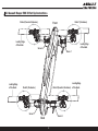
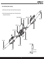
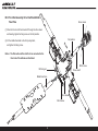
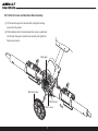
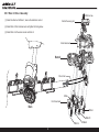
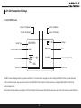
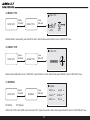
c
ctiv
olle
e pit
ch
ad
3D qu
copt
INST
er
ANUA
M
N
IO
RUCT
Specification:
TYPE: Collective Pitch Electric 3D Quadcopter
Rotor Diameter: 118MM
Length:635 MM
Width: 365 MM
Weight: 986g w/out battery
Flying weight : 1240g w/battery
L
1.0 Important Information
Table of Contents
1.0 Important Information
1
2.0 Assault Reaper 500 3D Set up Instructions
2
(1) The Assault Reaper 500 3D is not a toy, this Multirotor utilizes high-tech components
and technologies to provide superior performance in flight. Improper use of this
product can result in serious injury or even death. Please read this manual carefully
before use and be conscious of your own personal safety and the safety of others
3.0 Assault Reaper 500 3D Assembly
3-13
4.0 Main Controller Set Up Guidelines
14
5.0 Brushless Speed Controller Set Up
15
when operating this product. HobbyKing / the seller assumes no liability for the
operation or use of this product.
(2) This product is intended for use by experienced pilots aged 14 years or more. Any
minors wishing to fly this product must be accompanied by a responsible adult.
6.0 T-SIX Radio Settings
16-21
7.0 Binding the Transmitter and Receiver
22
8.0 Normal Flight Settings
23
9.0 Aerobatic Flight Settings
24
(3) When selecting a flying site for this product please be sure to obtain the relevant
permission from the owner before flying. HobbyKing accept no liability for any safety
duties or fines rising from operation, usage and misuse after purchase of the product.
1
2.0 Assault Reaper 500 3D Set Up Instructions
Rotor4 (Counter-Clockwise)
Leading Edge
of the blade
Leading Edge
of the blade
Rotor1 (Clockwise)
Front
Servo 4
Servo 1
Rotor2 (Counter-Clockwise)
Rotor3 (Clockwise)
Servo 3
Servo 2
Back
2
Leading Edge
of the blade
Leading Edge
of the blade
3.0 Assault Reaper 500 3D Assembly
No.1 Front Pulley Block Assembly
(1) Slide the drive belt through the left and right fixed tubes respectively.
Right fixed tube
(2) Face the fixed tube gap downwards, secure to the front pulley block,
and tighten the fixing screw.
M2x8 screw
Drvien belt
M2x8 screw
nt
Fro
Left fixed tube
Servo 1
M2 fixing nut
Drvien belt
M2 fixing nut
Front pulley block
Servo 4
3
Face the fixed
tube gap down
No.2 Back Pulley Block Assembly
(1) Slide the drive belt through the left and right fixed tubes respectively.
(2) Face the fixed tube gap downwards, secure to the back pulley block,
and tighten the fixing screw.
Back pulley block
Right fixed tube
M2x8 screw
Drvien belt
M2x8 screw
Servo 2
Left fixed tube
ck
Ba
M2 fixing nut
Drvien belt
M2 fixing nut
Servo 3
Face the fixed
tube gap down
4
NO.3 Front End Assembly Drive Shaft And Middle
Fixed Tube
Driven wheel
(1) Place the front end of the drive shaft through the drive wheel
and bearing, tighten the fixing screw on the flat position.
(2) Fit the middle fixed tube to the front pulley block,
and tighten the fixing screw.
Flat position
Fr
on
t
Notice: The Flat section of the shaft is to be connected to the
front end of the airframe as illustrated.
M3x3 screw
M2 fixing nut
Driven shaft
Middel fixed tube
M3x3 screw
M2x8 screw
5
NO.4 Rear End Assembly Drive Shaft and Middle Fixed Tube.
Middel fixed tube
M2x8 screw
Driven shaft
Ba
ck
M2 fixing nut
Driven wheel
M3x3 screw
(1) Slide the back end of the drive shaft through the
drive wheel and bearing, tighten the fixing screw on
the second flat position.
Second flat position
First flat position
(2) Fit the middle fixed tube to the back pulley block,
and tighten the fixing screw.
6
NO.5 Main Drive Gear and Brushless Motor Assembly.
(1) Fit the main drive gear onto the drive shaft, and tighten the fixing
screw on the flat position.
(2) Fit the brushless motor to the back pulley block, move it up and down
until the main drive gear and motor mesh smoothly, then tighten the
fixing screw to secure.
Motor gear
Main driven gear
M3x10 screw
M3x3 screw
7
Back
NO.6 Instructions For Drive Belt Assembly
(1) The arrows represent the rotation direction.
(2) When assembling the drive belt try to keep it tight to avoid vibration
in operation.
Rotate the end of the drive belt 90 degrees
counter-clockwise when assembled.
Front
Rotate the end of the drive belt 90 degrees
clockwise when assembled.
Rotor4
Rotor1
Rotor3
Rotor2
Rotate the end of driven belt 90
degrees clockwise when assembled.
Rotate the end of drive belt 90
degrees counter-clockwise when
assembled.
Back
8
NO.7 Rotor 2 / Rotor 4 Assembly
M2x14 screw
(1) Install the drive belt to Rotor 2, ensure the rotation is correct.
Control the swing arm
(2) Install Rotor 2 front and rear seat, and tighten the fixing screw.
(3) Install Rotor 4 in the same manner as Rotor 2.
Back fixed seat
Rotor2
Driven belt
M2x6
Front fixed seat
Back
PB2x8
PB2x10
PB2x14
9
PB2x8
NO.8 Rotor 1 / Rotor 3 Assembly
M2x14
(1) Install the drive belt to Rotor 3, ensure the rotation is correct.
(2) Install the Rotor 3 front and rear fixed seat, and tighten the fixing screw.
Control the swing arm
(3) Install Rotor 1 in the same manner as Rotor 3.
Back fixed seat
Rotor3
M2x6
Driven belt
Front fixed seat
Back
PB2x14
PB2x8
PB2x10
PB2x8
10
No.9 Pull Rod Assembly
Pull rod
90°
Pull rod
90°
(1) Once the steering servos have been positioned to
centre, the steering gear control swing arm must be
positioned at an angle of 90 degrees to ensure correct
operation.
Pull rod
(2) Connect the pull rod joint buckle to the ball end, the
propeller PITC should be at an angle of 0 degrees.
If necessary adjust this accordingly.
Pull rod
11
No.10 Reinforcing Plate, Skid Landing and Propeller Assembly.
Front
M3x14 screw
M3 fixing nut
Leading Edge
of the blade
Reinforcing plate
(1) Install the reinforcing plate to the bottom of the front back pulley block.
KB2x5
(2) Install the bottom cover and skid landing to the bottom of the front,
back pulley block.
Skid landing
PA2x11
Bott
om c
over
(3) Install the propeller into the propeller clip according to the rotation.
Leading Edge
of the blade
M3x14
Leading Edge
of the blade
M3 fixing nut
M3 fixing nut
Back
Reinforcing plate
KB2x5
PA2x11
12
Skid landing
Leading Edge
of the blade
No.11 ESC, Main Controller, Receiver, Battery,
Canopy Assembly
Canopy
Front
Canopy support beam
(1) Install the ESC to the backend of the mount plate.
(2) Install the main controller to the mount plate.
(3) Install the receiver to the mount plate.
Battery
(4) Install the battery to the mount plate.
(5) For wiring diagrams please refer to 4.0: main controller port instructions
and 5.0: ESC instructions.
Receiver
(6) Fix the canopy to the support beam.
Main controller
Brushless ESC
Canopy support beam
Back
13
4.0 Main Controller Set Up Guidelines
11
12
13
7
10
9
8
6
14
5
4
3
2
1
1
AUX1 IN: connect to receiver AUX1 port
2
Servo 1: connect to servo 1
3
Servo 2: connect to servo 2
4
Servo 3: connect to servo 3
5
Servo 4: connect to servo 4
6
THRO OUT: connect to ESC
7
RUDD IN: connect to receiver RUDD port
8
THRO IN: connect to receiver THRO port
9
AILE IN: connect to receiver AILE port
10
ELEV IN: connect to receiver ELEV port
11
12
13
14
ELEV G.S: Lift (front and back) gyroscope sensitivity adjustment knob, to increase by clockwise (+), Will increase the front and back
balance effect of the fuselage (fuselage steady is the best); reverse to reduce the balance effect.
AILE G.S:Aileron (left and right) gyroscope sensitivity adjustment knob, to increase by clockwise (+), Will increase the left and right
balance effect of the fuselage (fuselage steady is the best); reverse to reduce the balance effect.
ELEV/AILE EXT:Lift (front and back)/Aileron (left and right) Servo stroke ATV adjustment knob, to increase by clockwise (+), servo
became more sensitive; reverse is more slow.
Setting mode switch: WK is flight mode; ADJ is debug mode, can not fly in this mode.
14
5.0 Brushless Speed Controller Set up
Connect to main controller
THRO OUT port
Black——Yellow
Blue——Green
Brushless Motor
Red——Red
Connect to battery
Attention: The brushless motor should rotate in a clockwise direction, if not, exchange any two the motor connection wires to obtain the correct rotation.
15
6.0 T-SIX Transmitter Settings
6.1 Initial INFO Screen
Elevator Trim(Mode 1)
Throttle Trim(Mode 1)
Throttle Trim(Mode 2)
Elevator Trim(Mode 2)
Model Type
Current model number
7.2V
REAPER50
MDL 1
Current Model
Voltage
DN 06:00
Time
[ NORM ]
Helicopter Flight Mode
HELI
Rudder Trim
Aileron Trim
The INFO screen is displayed when the power is switched on. The screen has a two-page menu and rotating the ROLLER to the right moves forward
to the Function list screen, when you wish to return to the Initial INFO Screen from the Function list screen, rotating the ROLLER to the left returns
to the previous screen.
The function list screen allows you to display all of the information from the sensor attached to the receiver as well as the timer and key model information.
16
(4) Trim set up: The trim set up function allows servo movement
(1) Voltage: When the transmitter voltage drops below 4.3 volts,
“Warning Low Battery” will flash along with an alarm sound. If you
are flying when this occurs, land immediately.
adjustment.
(5) Model display: you can see the selected model directly after your
(2) Timer: Timer function allows you to program a Count Down timer or
model type has been selected.
Stop Watch (count up timer) to display on the main screen.
(3) Model Type: model type programs the selected model memory to
function in Helicopter or Airplane programming. You should
program the model type first when setting up a new model.
6.2 Names and Functions of the Input Key
List
Enter
ROLLER
UP
Down
FUNCTION LIST
MODEL SEL
D/R&EXPO
TRAVEL ADJ
SUB TRIM
GYRO
1/2
THRO CUR
PITC CUR
SWASH MIX
MIX 1
MIX 2
The T-SIX utilizes a roller that can be rotated or pressed along with four buttons, LIST, ENTER, UP and DOWN that are used to access and program the functions.
17
(1) LIST Key: when this key is pressed the screen changes to the Function Listing screen.
(2) ENTER Key: If this key is pressed when the INFO screen is being displayed, the screen will change to the My list screen. This can be used for moving
to each of the other functions.
(3) Up Key: if this key is pressed the select cursor will move up to your desired menu or list.
(4) DOWN Key: if this key is pressed the select cursor will move down to your desired menu or list.
(5) ROLLER: Press the ROLLER to access screens or functions. Or rotate the ROLLER to adjust values or to select options.
(6) Select Cursor: move the select cursor, then press the ROLLER and the screen will back to previous Menu.
6.3 MODEL SET
Initial INFO
Screen
MODEL SEL
Press
ROLLER
Rotate
ROLLER
FUNCTION LIST
MODEL SEL
Press
ROLLER
1: MODEL
2: MODEL
3: MODEL
4: MODEL
5: MODEL
6: MODEL 6
7: MODEL 7
8: MODEL 8
9: MODEL 9
10: MODEL 10
1
2
3
4
5
Rotate ROLLER to choose “MODEL 1”, press ROLLER to confirm, then the screen will display
“DOWNLOAD...” and the transmitter will “beep” 3 times, this denotes that the choice is successful and it will return to the function menu automatically.
6.4 MODEL NAME
FUNCTION LIST
MODEL NAME
Rotate/press
ROLLER
SETUP LIST
Rotate
ROLLER
MODEL NAME
Press
ROLLER
Rotate ROLLER to choose and change the settings and press the ROLLER to confirm. When finished,
Press the ROLLER to return to the FUNCTION LIST menu.
18
MODEL 1
REAPER50
! ” # $ % & °[ ] * +,- . / 01234
56789 : ;< = > ? QABCDEFGHI
JKLMNOPQRSTUVWXYZ
6.5 MODEL TYPE
MODEL TYPE
Rotate
ROLLER
SETUP LIST
MODEL TYPE
Press
ROLLER
ACRO
HELI
Rotate ROLLER to choose HELI, press ROLLER to confirm. When finished, press ROLLER to return to SETUP LIST menu.
6.6 SWASH TYPE
SETUP LIST
SWASH TYPE
Rotate
ROLLER
SWASH TYPE
Press
ROLLER
1 SERVO90°
Rotate and press ROLLER to choose “1 SERVO90°”, press ROLLER to confirm. When finished, press ROLLER to return to SETUP LIST menu.
6.7 REVERSE
SETUP LIST
N= Normal
REVERSE
Rotate
ROLLER
REVERSE
Press
ROLLER
THRO-N
AILE-N
ELEV-N
RUDD-N
GYRO-N
PITC-R
R= Reverse
THRO, ELEV, GYRO, AILE, RUDD: choose the normal. PITC: choose the reversion. When finished, press ROLLER to return to FUNCTION LIST menu.
19
6.8 GYRO
FUNCTION LIST
Rotate
ROLLER
GYRO
GYRO
Press
ROLLER
RATE
Rotate ROLLER to choose and change the settings and press ROLLER
SW-GYRO
POS0:
80.0%
POS1:
70.0%
POS1:
50.0%
to confirm. When finished, press ROLLER to return to FUNCTION LIST
menu.
6.9 THRO CUR
FUNCTION LIST
Rotate
ROLLER
THRO CUR
THRO CUR
NORM STU HOLD
L 0.0 100 100.0
2 42.0 88.0
3 70.0 80.0
4 85.0 88.0
H 100 100
Press
ROLLER
NORM
(%)
THRO CUR
NORM STU HOLD
L 0.0 100 100.0
2 42.0 88.0
3 70.0 80.0
4 85.0 88.0
H 100 100
STU
THRO CUR
NORM STU HOLD
L 0.0 100 100.0
2 42.0 88.0
3 70.0 80.0
4 85.0 88.0
H 100 100
Rotate ROLLER to choose and change the settings and press ROLLER
to confirm. When finished, press ROLLER to return to FUNCTION LIST
menu.
HOLD
20
(%)
(%)
6.10 PITC CUR
FUNCTION LIST
Rotate
ROLLER
PITC CUR
PITC CUR
NORM STU HOLD
0.0
L 40.0 25.0
2 50.0 38.0 25.0
3 58.0 50.0 50.0
4 68.0 63.0 75.0
100
H 75.0 75.0
Press
ROLLER
NORM
Rotate ROLLER to choose and change the settings and press ROLLER
to confirm. When finished, press ROLLER to return to Initial Info Screen.
(%)
PITC CUR
NORM STU HOLD
L 40.0 25.0
0.0
2 50.0 38.0 25.0
3 58.0 50.0 50.0
4 68.0 63.0 75.0
H 75.0 75.0
100
STU
PITC CUR
NORM STU HOLD
L 40.0 25.0
0.0
2 50.0 38.0 25.0
3 58.0 50.0 50.0
4 68.0 63.0 75.0
H 75.0 75.0
100
For details, please refer to T-SIX user manual.
HOLD
21
(%)
(%)
7.0 Binding the Transmitter and Receiver
binding plug
(1) Insert the bind plug in the BATT/ BIND slot on the receiver.
(2) Move the throttle sticker to the LOW/OFF position. Then power on the radio.
(3) Connect the flight battery to the receiver, the LED will flash quickly.
(4) When the LED becomes a solid continuous light binding is complete.
(5) Always remove the bind plug from the receiver once bound.
Attention: If the receiver’s LED flashes slowly whilst binding, disconnect the flight battery and wait for 60 seconds then power on the transmitter
and repeat the process again.
22
8.0 Normal flight
Aircraft(
is the nose direction)
Mode 1
Up / down
Forward / backward
Left-leaning /
right-leaning
Head direction
is horizontal level
23
Mode 2
9.0 Acrobatic flight
Aircraft(
is the nose direction)
Mode 1
Up / down
Forward / backward
Left-leaning /
right-leaning
Head direction
is horizontal level
24
Mode 2
25