1
Driver Manual
CIF Device Driver
Windows
V1.xxx ... V3.2xx
Hilscher Gesellschaft für Systemautomation mbH
www.hilscher.com
DOC030501DRV14EN | Revision 14 | English | 2013-02 | Released | Public
Introduction
2/121
Table of Contents
1
Introduction.............................................................................................................................................4
1.1 About this Document......................................................................................................................4
1.2 List of Revisions .............................................................................................................................4
1.3 Operating Systems.........................................................................................................................5
1.4 Data Transfer .................................................................................................................................5
1.5 Terms for this Manual ....................................................................................................................5
1.6 Legal Notes ....................................................................................................................................6
1.6.1
1.6.2
1.6.3
1.6.4
1.6.5
1.6.6
Copyright ........................................................................................................................................... 6
Important Notes................................................................................................................................. 6
Exclusion of Liability .......................................................................................................................... 7
Warranty............................................................................................................................................ 7
Export Regulations ............................................................................................................................ 7
Registered Trademarks ..................................................................................................................... 7
2
Getting Started........................................................................................................................................8
3
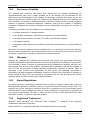
Communication ......................................................................................................................................9
3.1 About the User Interface ................................................................................................................9
3.1.1 Message Interface and Process Data Image..................................................................................... 9
3.1.2 The Protocol Dependent and Independent User Interface ................................................................ 9
3.2
3.3
Interface Structure........................................................................................................................10
Message and Process Data Communication...............................................................................11
3.3.1 Message Communication ................................................................................................................ 11
3.3.2 Communication with a Process Image ............................................................................................ 13
3.3.3 Overview ......................................................................................................................................... 18
3.4
The Software Structure on the Communication Boards ..............................................................19
3.4.1 The Real-Time Operating System ................................................................................................... 19
3.4.2 The Protocol Task ........................................................................................................................... 20
4
DOS/Windows 3.xx Function Library .................................................................................................21
4.1 Toolkit Contents ...........................................................................................................................23
4.1.1 Toolkit File Description .................................................................................................................... 24
4.2
4.3
4.4
4.5
5
Using with DOS and Windows 3.xx .............................................................................................24
Using Visual Basic 3.0/4.0 (16 bit) ...............................................................................................25
Writing an own Driver or Library ..................................................................................................25
Using the Source Code ................................................................................................................25
The Device Driver .................................................................................................................................26
5.1 Windows Operating System Timing Behaviour............................................................................26
5.2 Windows 9x, Windows NT and Windows 2K/XP/Vista/7/8 ..........................................................28
5.2.1
5.2.2
5.2.3
5.2.4
5.2.5
5.3
Windows CE (up to 5.0) ...............................................................................................................38
5.3.1
5.3.2
5.3.3
5.3.4
5.3.5
5.3.6
5.4
General Information about Windows CE Drivers ............................................................................. 40
Contents for Windows CE ............................................................................................................... 41
Compiling the Source Code............................................................................................................. 44
Installation of the Device Driver....................................................................................................... 47
Configure the Device Driver ............................................................................................................ 48
Integration into a Windows CE Image ............................................................................................. 53
Windows CE 6.0...........................................................................................................................54
5.4.1
5.4.2
5.4.3
5.4.4
5.4.5
6
Contents for Windows 9x, NT and 2K/XP/Vista/7/8......................................................................... 30
Installation of the Device Driver....................................................................................................... 31
Configure the Windows 9x and Windows NT Driver ........................................................................ 35
Configure the Driver under Windows 2K and later .......................................................................... 36
System Startup................................................................................................................................ 37
General Information about Windows CE Drivers ............................................................................. 56
Contents for Windows CE ............................................................................................................... 57
Compiling the Source Code............................................................................................................. 61
Installation of the Device Driver....................................................................................................... 65
Configure the Device Driver ............................................................................................................ 66
Programming Instructions ..................................................................................................................70
6.1 Include the Interface API in Your Application...............................................................................70
6.2 Open and Close the driver ...........................................................................................................70
6.3 Writing an Application ..................................................................................................................71
6.3.1 Determine Device Information ......................................................................................................... 71
CIF Device Driver | Windows
DOC030501DRV14EN | Revision 14 | English | 2013-02 | Released | Public
© Hilscher, 1996-2013
Introduction
3/121
6.3.2 Message Based Application ............................................................................................................ 73
6.3.3 Process Data Image Based Application .......................................................................................... 77
6.4
The Demo Application..................................................................................................................79
6.4.1 C-Example....................................................................................................................................... 79
6.4.2 C++-Example .................................................................................................................................. 81
7
The Application Programming Interface............................................................................................82
7.1 Differences of the Operating Systems .........................................................................................83
7.1.1 Function Parameters ....................................................................................................................... 83
7.1.2 Timer Resolution ............................................................................................................................. 83
7.2
7.3
7.4
7.5
7.6
7.7
7.8
7.9
7.10
7.11
DevOpenDriver() ..........................................................................................................................84
DevCloseDriver()..........................................................................................................................85
DevGetBoardInfo() .......................................................................................................................86
DevInitBoard() ..............................................................................................................................87
DevExitBoard().............................................................................................................................88
DevPutTaskParameter() ..............................................................................................................89
DevGetTaskParameter() ..............................................................................................................90
DevReset() ...................................................................................................................................91
DevSetHostState() .......................................................................................................................92
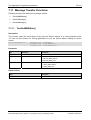
Message Transfer Functions........................................................................................................93
7.11.1 DevGetMBXState().......................................................................................................................... 93
7.11.2 DevPutMessage()............................................................................................................................ 94
7.11.3 DevGetMessage() ........................................................................................................................... 96
7.12
7.13
7.14
7.15
DevGetTaskState() ......................................................................................................................98
DevGetInfo().................................................................................................................................99
DevTriggerWatchdog()...............................................................................................................102
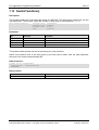
Process Data Transfer Functions ..............................................................................................103
7.15.1 DevExchangeIO().......................................................................................................................... 104
7.15.2 DevExchangeIOErr() ..................................................................................................................... 105
7.15.3 DevExchangeIOEx()...................................................................................................................... 107
7.16 DevReadWriteDPMRaw() ..........................................................................................................108
7.17 DevDownload() ..........................................................................................................................109
8
Error Numbers ....................................................................................................................................110
8.1 List of Error Numbers .................................................................................................................110
9
Development Environments..............................................................................................................114
9.1 Microsoft Software Development Tools .....................................................................................116
9.1.1 Visual Basic 3.0, 4.0 (16 bit).......................................................................................................... 116
9.1.2 Microsoft Visual Basic 4.0, 5.0 (32 bit) .......................................................................................... 116
9.2
Borland Software Development Tools .......................................................................................117
9.2.1 Borland C 5.0, Borland C-Builder V1.0 ......................................................................................... 117
9.2.2 Borland Delphi............................................................................................................................... 118
9.2.3 National Instruments CVI LabWindows 4.1 ................................................................................... 119
10
Appendix .............................................................................................................................................120
10.1 List of Tables..............................................................................................................................120
10.2 List of Figures.............................................................................................................................120
10.3 Contacts .....................................................................................................................................121
CIF Device Driver | Windows
DOC030501DRV14EN | Revision 14 | English | 2013-02 | Released | Public
© Hilscher, 1996-2013
Introduction
1
1.1
4/121
Introduction
About this Document
This manual describes the application programming interface (API) to our communication boards.
The interface is designed to give the user an easy access to all the communication board
functionality.
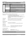
1.2
List of Revisions
Rev
Date
Version
Name
12
2010-02-08
3.210
MT
Chapter
Revision
Support for Vista (32/64Bit) / Windows 7 (32/64Bit) added
- CIFNTDLL / CIF95DLL only available for Win9X and NT
- Driver installation splitted into
Win 9x/NT,
Windows 2000/XP/Vista/7 32 Bit and
Windows Vista/7 64 Bit
Section List of Error Numbers: Hints integrated into Table 20.
13
14
2011-10-20
2013-02-27
3.280
3.290
RM
RM
5.1
New chapter Windows Operating System Timing Behaviour
added
- Information about Windows driver time issues added
- Diagrams with access times added
5.2.1
Content description of the DRVPRG directory updated.
7
Information about functions with performance improvements
added.
All
Support for Windows 8 (32/64 Bit) added.
Table 1: List of Revisions
CIF Device Driver | Windows
DOC030501DRV14EN | Revision 14 | English | 2013-02 | Released | Public
© Hilscher, 1996-2013
Introduction
1.3
5/121
Operating Systems
!
On DOS and Windows 3.xx systems, we are offering a C-function library or DLL (Windows
3.xx). There is no device driver used to get access to the communication boards.
!
For Windows 9x, Windows NT and Windows 2K/XP/Vista/7/8 we are using device drivers.
These drivers are running in the kernel (Ring 0) of the operating system. The communication
between the application and the driver is done by a DLL. This DLL can be statically or
dynamically linked to the application.
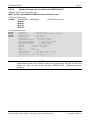
1.4
Data Transfer
On the communication boards, we distinguish between two types of data transfer.
!
The first one is the message oriented data transfer used by message oriented protocols.
!
The second one is the data exchange with process images from I/O based protocols.
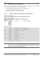
1.5
Terms for this Manual
Term
Description
DPM
DPM Dual-Port Memory, this is the physical interface to all communication board (DPM is also used
for PROFIBUS-DP Master)
CIF
Communication InterFace
COM
COmmunication Module
HOST
Application on the PC or a similar device
DEVICE
Synonym for communication interfaces or communication modules
RCS
Real-time Communicating System, this is the name of the
operating system that runs on the communication boards
DLL
Dynamic Link Library
WDM
Windows Driver Model
Table 2: Terms for this Manual
CIF Device Driver | Windows
DOC030501DRV14EN | Revision 14 | English | 2013-02 | Released | Public
© Hilscher, 1996-2013
Introduction
1.6
1.6.1
6/121
Legal Notes
Copyright
© Hilscher, 1996-2013, Hilscher Gesellschaft für Systemautomation mbH
All rights reserved.
The images, photographs and texts in the accompanying material (user manual, accompanying
texts, documentation, etc.) are protected by German and international copyright law as well as
international trade and protection provisions. You are not authorized to duplicate these in whole or
in part using technical or mechanical methods (printing, photocopying or other methods), to
manipulate or transfer using electronic systems without prior written consent. You are not permitted
to make changes to copyright notices, markings, trademarks or ownership declarations. The
included diagrams do not take the patent situation into account. The company names and product
descriptions included in this document may be trademarks or brands of the respective owners and
may be trademarked or patented. Any form of further use requires the explicit consent of the
respective rights owner.
1.6.2
Important Notes
The user manual, accompanying texts and the documentation were created for the use of the
products by qualified experts, however, errors cannot be ruled out. For this reason, no guarantee
can be made and neither juristic responsibility for erroneous information nor any liability can be
assumed. Descriptions, accompanying texts and documentation included in the user manual do
not present a guarantee nor any information about proper use as stipulated in the contract or a
warranted feature. It cannot be ruled out that the user manual, the accompanying texts and the
documentation do not correspond exactly to the described features, standards or other data of the
delivered product. No warranty or guarantee regarding the correctness or accuracy of the
information is assumed.
We reserve the right to change our products and their specification as well as related user
manuals, accompanying texts and documentation at all times and without advance notice, without
obligation to report the change. Changes will be included in future manuals and do not constitute
any obligations. There is no entitlement to revisions of delivered documents. The manual delivered
with the product applies.
Hilscher Gesellschaft für Systemautomation mbH is not liable under any circumstances for direct,
indirect, incidental or follow-on damage or loss of earnings resulting from the use of the information
contained in this publication.
CIF Device Driver | Windows
DOC030501DRV14EN | Revision 14 | English | 2013-02 | Released | Public
© Hilscher, 1996-2013
Introduction
1.6.3
7/121
Exclusion of Liability
The software was produced and tested with utmost care by Hilscher Gesellschaft für
Systemautomation mbH and is made available as is. No warranty can be assumed for the
performance and flawlessness of the software for all usage conditions and cases and for the
results produced when utilized by the user. Liability for any damages that may result from the use
of the hardware or software or related documents, is limited to cases of intent or grossly negligent
violation of significant contractual obligations. Indemnity claims for the violation of significant
contractual obligations are limited to damages that are foreseeable and typical for this type of
contract.
It is strictly prohibited to use the software in the following areas:
!
for military purposes or in weapon systems;
!
for the design, construction, maintenance or operation of nuclear facilities;
!
in air traffic control systems, air traffic or air traffic communication systems;
!
in life support systems;
!
in systems in which failures in the software could lead to personal injury or injuries leading to
death.
We inform you that the software was not developed for use in dangerous environments requiring
fail-proof control mechanisms. Use of the software in such an environment occurs at your own risk.
No liability is assumed for damages or losses due to unauthorized use.
1.6.4
Warranty
Although the hardware and software was developed with utmost care and tested intensively,
Hilscher Gesellschaft für Systemautomation mbH does not guarantee its suitability for any purpose
not confirmed in writing. It cannot be guaranteed that the hardware and software will meet your
requirements, that the use of the software operates without interruption and that the software is
free of errors. No guarantee is made regarding infringements, violations of patents, rights of
ownership or the freedom from interference by third parties. No additional guarantees or
assurances are made regarding marketability, freedom of defect of title, integration or usability for
certain purposes unless they are required in accordance with the law and cannot be limited.
Warranty claims are limited to the right to claim rectification.
1.6.5
Export Regulations
The delivered product (including the technical data) is subject to export or import laws as well as
the associated regulations of different counters, in particular those of Germany and the USA. The
software may not be exported to countries where this is prohibited by the United States Export
Administration Act and its additional provisions. You are obligated to comply with the regulations at
your personal responsibility. We wish to inform you that you may require permission from state
authorities to export, re-export or import the product.
1.6.6
Registered Trademarks
Windows® 2000 / Windows® XP / Windows® Vista / Windows® 7 / Windows® 8 are registered
trademarks of Microsoft Corporation.
Adobe-Acrobat® is a registered trademark of the Adobe Systems Incorporated.
CIF Device Driver | Windows
DOC030501DRV14EN | Revision 14 | English | 2013-02 | Released | Public
© Hilscher, 1996-2013
Getting Started
2
8/121
Getting Started
This section describes how to configure a CIF device and how to check a configuration which
already exists on the CIF hardware against an application local configuration.
Usually a fieldbus configuration is created and checked by SyCon (System Configurator). After
creating a valid configuration SyCon is able to export the configuration into a database file (.DBM).
This exported file can be used in the driver to run the automatic database checking and download
(see DevInitBoard() function). By using this functionality, an application can always be sure the CIF
card is correctly configured.
If an applications generates an own configuration (mostly SoftPLCs) it could be necessary to
compared it against an actual CIF configuration. To enable a configuration check in such cases,
the external C module CifConfiguration.c can be used. This module includes all necessary
functions to read the actual configuration from the hardware and to compare it against an
application local configuration.
Overview
!
Chapter Communication includes general definitions and describes the fundamentals about
data transfers between an application and the communication boards.
!
The features of the driver for Dos and Windows 3.xx is described in chapter DOS/Windows
3.xx Function Library.
!
Chapter The Device Driver describes an overview, the installation and configuration of the
device driver for Windows 9x, Windows NT, Windows 2K/XP/Vista/7/8 and Windows CE.
!
The important chapter Programming Instructions describes the basic functionality of using
the device driver and presents an example.
!
All functions of the device driver are explained in chapter The Application Programming
Interface.
!
Chapter Error Numbers lists a detail description of the error numbers
!
Chapter Development Environments informs about the Microsoft and Borland development
tools.
CIF Device Driver | Windows
DOC030501DRV14EN | Revision 14 | English | 2013-02 | Released | Public
© Hilscher, 1996-2013
Communication
3
9/121
Communication
3.1
About the User Interface
3.1.1
Message Interface and Process Data Image
There are two ways of data transfer between the HOST and the DEVICE:
!
Message oriented data transfer
Telegram oriented protocols like PROFIBUS-FMS the data transfer happens with messages,
which will be send or received over two mailboxes in the dual-port memory. There is one
mailbox for each direction (Send direction and receive direction). Normally, the data transfer
will be controlled by events.
!
Process data image transfer
In fieldbus systems, which handle input and output data, like PROFIBUS-DP or InterBus-S,
there is a data image of the process data inside the dual-port memory. Input data and output
data have their own area and the data transfer normally happens cyclic.
3.1.2
The Protocol Dependent and Independent User Interface
The user interface via the dual-port memory of the communication interface and the
communication module has two parts, a protocol dependent, and a protocol independent part.
The protocol independent part of the dual-port memory is the main part of the data between HOST
and DEVICE.
The particular protocol dependent part are the parameters for initializing the protocol and the
message structure for exchanging jobs between the HOST and the DEVICE. These jobs are called
messages. The structure of a message has reached a high standard. This means that changing to
another protocol is very simple.
The exactly composition of a message is described in the particular protocol manual. The
difference between the various protocols are only the protocol parameters. The data model of the
dual-port memory and the mechanism of message exchange are always the same.
CIF Device Driver | Windows
DOC030501DRV14EN | Revision 14 | English | 2013-02 | Released | Public
© Hilscher, 1996-2013
Communication
3.2
10/121
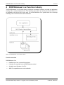
Interface Structure
The interface to the communication board is based on a dual-port memory. The following picture
shows the various parts of the dual-port memory.
Figure 1: Interface Structure
One dual-port memory map for all CIFs/COMs and all protocols with
!
Process image for input and output data
!
Two mailboxes for message communication
!
Parameter area for simple protocols (baudrate, data bits, parity ...)
!
Protocol status information (telegram counter, last error, valid slaves...)
!
System status (firmware name/version, CIF revision/serial number...)
CIF Device Driver | Windows
DOC030501DRV14EN | Revision 14 | English | 2013-02 | Released | Public
© Hilscher, 1996-2013
Communication
3.3
11/121
Message and Process Data Communication
3.3.1
Message Communication
A message is a unique data structure in which the user transmits or receives commands and data
from the CIF or COM.
A message consists of an 8 byte message header, an 8 byte telegram header and up to 247 bytes
of user data.
!
Message Header
Used from operating system for transportation of the message. It is
defined in this manual and constant for the application.
!
Telegram Header
Defines the action for the protocol task
!
User data
Send/received data
Parameter
Type
Meaning
Msg.Rx
byte
Number of Receiving Task
Msg.Tx
byte
Number of Sending Task
Msg.Ln
byte
Number of Data length
Msg.Nr
byte
Number of Message for Identification
Msg.A
byte
Number of Responses
Msg.F
byte
Error Code
Msg.B
byte
Number of Command
Msg.E
byte
Completion
Msg.DeviceAdr
byte
Communication Reference
Msg.DataArea
byte
Data Block
Msg.DataAdr
word
Object Index
Msg.DataIdx
byte
Object Subindex
Msg.DataCnt
byte
Data Quantity
Msg.DataType
byte
Data Type
Msg.Fnc
byte
Service
Msg.D[0-246]
byte
User Data
Message Header
Telegram Header
Telegram User Data
Table 3: General structure of a message
The meaning of the telegram header is an example for PROFIBUS-FMS. For other protocols the
structure is the same but, the parameters change as for example with Modbus Plus, from
communication reference to slave address, object index to register address or service to function
code.
The driver transfers a message independent from the protocol and works transparent. The
message reproduces the telegram.
CIF Device Driver | Windows
DOC030501DRV14EN | Revision 14 | English | 2013-02 | Released | Public
© Hilscher, 1996-2013
Communication
3.3.1.1
12/121
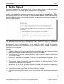
Sending (Putting) and Receiving (Getting) Messages
The user creates the send
message and writes it in the send
mailbox. This message is set to be
send by the
DevPutMessage() command.
The device takes out the message,
puts it in an internal queue and
signals this action to the HOST.
The queue is handled by the FIFO
principle. If the message is on the
first position, it will be decoded to
generate the send telegram.
If the device receives the
acknowledge telegram, it generates
a receive message and puts it in
the queue.
If the message is in the first position
and the receive mailbox is empty,
the message will be copied in the
mailbox and set valid.
The user takes out the receive
message, with the
DevGetMessage() command,
which sets the mailbox state to
empty.
Figure 2: Sending (Putting) and Receiving (Getting) Messages
CIF Device Driver | Windows
DOC030501DRV14EN | Revision 14 | English | 2013-02 | Released | Public
© Hilscher, 1996-2013
Communication
3.3.2
13/121
Communication with a Process Image
In fieldbus systems with IO devices like PROFIBUS-DP or InterBus-S there is a process image of
the IO data available directly in the dual-port memory. The access is the same if the CIF or COM
works as master or slave. Depending on the application the user can choose between several
handshake modes, or if only byte consistence is required, the user can read and write without any
synchronization.
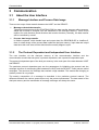
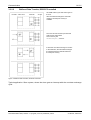
3.3.2.1
Direct Data Transfer, DEVICE Controlled
The CIF/COM starts by itself a data
exchange cycle if it is a master, or it
receives a data exchange cycle if it is
slave.
Now the user can read the new input
data and write the output data in the
dual-port memory.
This is done by the
DevExchangeIO() function.
The CIF/COM starts the next data
exchange cycle.
Figure 3: Direct Data Transfer, DEVICE Controlled
Typical application: Slave system, which must guarantee that the data from every master cycle
must be given to the user program.
CIF Device Driver | Windows
DOC030501DRV14EN | Revision 14 | English | 2013-02 | Released | Public
© Hilscher, 1996-2013
Communication
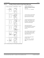
3.3.2.2
14/121
Buffered Data Transfer, DEVICE Controlled
CIF/COM makes cyclic data exchanges on
the bus.
After each data exchange the CIF/COM
checks, if the dual-port memory is
available.
The user can read out the input data and
write the new output data.
This is done by the
DevExchangeIO() function.
If there was one data exchange on the bus
in the meantime, the CIF/COM exchanges
the data between the internal buffer and
the dual-port memory.
Figure 4: Buffered Data Transfer, DEVICE Controlled
Typical application: Slave system, where the slave gets an interrupt with the next data exchange
cycle.
CIF Device Driver | Windows
DOC030501DRV14EN | Revision 14 | English | 2013-02 | Released | Public
© Hilscher, 1996-2013
Communication
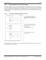
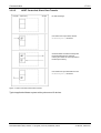
3.3.2.3
15/121
Uncontrolled Direct Data Transfer
The user reads and writes the process
image, with the DevExchangeIO()
function, at the same time like the
CIF/COM.
The CIF/COM does cyclic data exchanges
and after every exchange it makes an
update of the process image.
Figure 5: Uncontrolled Direct Data Transfer
CIF Device Driver | Windows
DOC030501DRV14EN | Revision 14 | English | 2013-02 | Released | Public
© Hilscher, 1996-2013
Communication
3.3.2.4
16/121
HOST Controlled, Buffered Data Transfer
Cyclic data exchange between internal
buffer and PROFIBUS.
User reads last input data and writes new
output data, with the
DevExchangeIO() command.
Data exchange continues.
CIF stops data exchange, puts the output
data in the internal buffer and the latest
input data in the dual-port memory.
User reads input data and writes output
data DevExchangeIO().
Figure 6: HOST Controlled, Buffered Data Transfer
Typical application: Easiest handshake in master and slave systems with a guaranteed
consistence of the complete process image.
CIF Device Driver | Windows
DOC030501DRV14EN | Revision 14 | English | 2013-02 | Released | Public
© Hilscher, 1996-2013
Communication
3.3.2.5
17/121
HOST Controlled, Direct Data Transfer
No data exchange.
User writes new output data, with the
DevExchangeIO() command.
CIF/COM starts one data exchange with
the output data from the dual-port
memory and writes the new input data in
the dual-port memory.
User reads new input data with the next
DevExchangeIO() command.
Figure 7: HOST Controlled, Direct Data Transfer
Typical application:Master system with synchronous IO devices.
CIF Device Driver | Windows
DOC030501DRV14EN | Revision 14 | English | 2013-02 | Released | Public
© Hilscher, 1996-2013
Communication
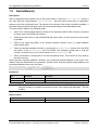
3.3.3
18/121
Overview
The following table list the bus systems and protocols and shows which communication has to be
used for the (user) data transfer.
I/O Communication
Message Communication
Read/Write
Send/Receive
PROFIBUS-DP Master
PROFIBUS-DPV1
-
PROFIBUS-DP Slave
PROFIBUS-DPV1
-
-
PROFIBUS-FMS
-
-
PROFIBUS-FDL
PROFIBUS-FDL
FDL defined
FDL transparent
InterBus Master (I/O)
InterBus Master (PCP)
-
InterBus Slave (I/O)
InterBus Slave (PCP)
-
CANopen Master (PDO)
CANopen Master (SDO)
-
CANopen Slave (PDO)
CANopen Slave (SDO)
-
DeviceNet Master (I/O)
DeviceNet Master
-
(Explicit Messaging)
DeviceNet Slave (I/O)
DeviceNet Slave
-
(Explicit Messaging)
ControlNet Slave (Scheduled
Data)
ControlNet Slave (Unscheduled Data)
-
SDS Master
-
-
AS-Interface Master
-
-
-
-
3964R
-
RK512
-
-
ASCII (Master mode)
ASCII (Slave mode)
-
Modbus RTU
-
-
Modbus Plus
-
-
-
Modnet 1/N
-
-
Modnet 1/SFB
Table 4: Bus Systems/Protocols and Communication for Data Transfer
Note 1:
!
For IO communication the driver function DevExchangeIO() is necessary.
!
For message communication the driver function DevPutMessage() and DevGetMessage()
are necessary.
Note 2:
!
The list above documents the user data.
!
The bus systems and the protocols also offer possibilities of diagnostic, parameter
telegrams, control telegrams and more. These are not listed above.
CIF Device Driver | Windows
DOC030501DRV14EN | Revision 14 | English | 2013-02 | Released | Public
© Hilscher, 1996-2013
Communication
3.4
19/121
The Software Structure on the Communication Boards
The software is based on an extremely modular architecture. The protocol itself is a self-contained
module which has no variables in common with any other software module apart from the
operating system. It is therefore possible to implement the protocol with the same software module
on all our boards, thus ensuring the greatest software quality.
The main parts of the firmware are the real-time operating system and the protocol task(s).
3.4.1
The Real-Time Operating System
The operating system can manage 7 tasks, and is optimized for real-time communications
services. It provides the following functions:
!
Distribution of computing time among the individual-tasks
!
Task communication
!
Memory management
!
Provision of time functions
!
Diagnostic and general management functions
!
Transmit and receive functions
The computing time is evenly distributed by the operating system among all tasks ready to run. A
task switch, i.e. switch over to the next task, takes place in cycles every millisecond.
If a task has to wait for an external event, e.g. for the receipt of data, it is no longer ready to run
and a task switch is performed immediately.
The available computing time and the maximum possible sum baud rate make sure, that a less
prior task is not completely blocked by a high priority task. Presumably the data through put is
lower in this case.
Communication between the tasks takes place by messages. These are the areas of memory
made available by the operating system into which the tasks write data. Transport of messages
from one task to another and notification to a task that a message is there is handled by the
operating system.
The operating system also manages the memory area for storage of the tasks and their stack.
Individual tasks can be deleted or reloaded.
A task can wait for an event and the operating system will restart the task when the event has
occurred, the time resolution is 1 millisecond.
The operating system can stop or start individual tasks and pass on certain jobs to them. The tasks
thus make available data in the trace buffer which is managed by the operating system.
The operating system communicates with the HOST (PC or a similar device) via the dual-port
memory interface. There is access to the individual-operating system functions and to the
individual tasks via the communications system.
CIF Device Driver | Windows
DOC030501DRV14EN | Revision 14 | English | 2013-02 | Released | Public
© Hilscher, 1996-2013
Communication
3.4.2
20/121
The Protocol Task
The protocol task is responsible for transmission of the data in accordance with the protocol. The
parameters it requires for this are taken from the dual-port memory or from the FLASH-memory.
A transmit job is always initiated with a message. This contains all the data to be transmitted.
These are provided with any control characters and checksums required and then output by
interrupt or DMA. At the same time, the corresponding monitoring periods are started. When the
data has been transferred or an error has occurred, a corresponding acknowledgment is returned
to the sender of the message.
Depending on the protocol, receive messages are restored after the transmission. Receiving is
done by interrupt or DMA. If a message has been received without error, it is passed on by
message to the PC via the dual-port memory interface.
I/O oriented protocol tasks work on the bus independently according to the given protocol
specification. The data transfer is not done by a message, but is done by direct reading or writing
to the send and receive data in the dual-port memory.
As the protocol task runs independently, a wide variety of protocols can be implemented on the
CIF, PC/104 or COM by replacing this task. Different tasks can also be used for the two serial
interfaces.
CIF Device Driver | Windows
DOC030501DRV14EN | Revision 14 | English | 2013-02 | Released | Public
© Hilscher, 1996-2013
DOS/Windows 3.xx Function Library
4
21/121
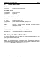
DOS/Windows 3.xx Function Library
The DOS/Windows 3.xx function library includes all necessary functions to make an application
working with a communication device. The interface is the same as used by the device drivers, so
an upgrade to this driver will be very easy. On a DOS/Windows 3.xx system there is no interrupt
handling of the communication boards available.
Figure 8: DOS/Windows 3.xx Function Library
Function overview
DOS/Windows 3.xx
!
Handles up to four communication board
!
Libraries are compiled in the LARGE-Memory model
!
Available as a Windows 3.xx DLL
!
ANSI C compatible source code available
CIF Device Driver | Windows
DOC030501DRV14EN | Revision 14 | English | 2013-02 | Released | Public
© Hilscher, 1996-2013
DOS/Windows 3.xx Function Library
22/121
Some functions are only for compatibility with the device driver like DevOpenDriver(),
DevCloseDriver() and DevGetDriverInfo(). These function do nothing when used in a
Windows 3.xx environment.
The following development platforms are used:
DOS
Microsoft Visual C++, V 1.5x
WINDOWS
Microsoft Visual C++, V 1.5x
CIF Device Driver | Windows
DOC030501DRV14EN | Revision 14 | English | 2013-02 | Released | Public
© Hilscher, 1996-2013
DOS/Windows 3.xx Function Library
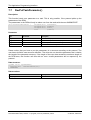
4.1
23/121
Toolkit Contents
The whole DOS/Windows 3.xx source code and library files are located on our System Software
CD, in the \DRVPRG\16Bit directory.
This directory contains a number of subdirectories.
Directory structure:
CD Path: DRVPRG
Header
- DUALPORT.H definition of the
communication interface dual port
memory structure
- RCS_USER.H definitions for the
communication interface operating
system (RCS)
- Fieldbus specific header files
CD Path: DRVPRG\16Bit
Subdirectory
Description
DLL
Windows 3.xx DLL (CifWinDl.DLL )
LIB
Function library for DOS (CifDOS.lib)
and Windows 3.xx
Description
Windows 3.xx DLL (CifWinDl.DLL )
(CifWin.lib)
Function library source code and
header files
Windows 3.xx DLL (CifWinDl.DLL )
Subdirectory
Description
Description
C
Simple Message and IO data transfer
source code example (Demo.c)
Simple Message and IO data transfer source
code example (Demo.c)
ASi
Simple AS Interface IO-View example
Simple AS Interface IO-View example
CANOpen
Simple CANopen IO-View example
Simple CANopen IO-View example
CtrlNet
Simple ControlNet IO-View example
Simple ControlNet IO-View example
DevNet
Simple DeviceNet IO-View example
Simple DeviceNet IO-View example
InterBus
Simple InterBus IO-View example
Simple InterBus IO-View example
Profibus\IOVIEW
Simple PROFIBUS IO-View example
Simple PROFIBUS IO-View example
Profibus\FMS
Simple PROFIBUS FMS example
Simple PROFIBUS FMS example
SDS
Simple SDS IO-View example
Simple SDS IO-View example
VBasic30
Visual Basic 3.0 demo program
Visual Basic 3.0 demo program including the
including the definition file CIFDEF.BAS definition file CIFDEF.BAS
PRG
CD Path: DRVPRG\16Bit\Demo
Table 5: Toolkit – Directory Structure
CIF Device Driver | Windows
DOC030501DRV14EN | Revision 14 | English | 2013-02 | Released | Public
© Hilscher, 1996-2013
DOS/Windows 3.xx Function Library
4.1.1
24/121
Toolkit File Description
The DOS library files
CIFDOS.LIB
Function library of the user interface
The Windows 3.xx files
CIFWINDL.DLL
Dynamic Link Library
CIFWINDL.LIB
DLL library file
CIFWIN.LIB
C-Function library
Common DOS and Windows 3.xx files
CIFUSER.H
Header file of the user interface
CIF_DPM.C
Function library source code
CIFWINDL.DEF
Function export definitions for the Windows 3.xx DLL
DPMI.C
Memory allocation functions for Windows 3.xx
DEMO.C
Source file of the demo program, demonstrates the use with a simple
communication protocol.
DEMO.H
Include file of the demo program
Demo program
DOS_DEMO.EXE
Demo program for DOS (created from DEMO.C)
WIN_DEMO.EXE
Test program for Windows 3.xx (created from DEMO.C)
4.2
Using with DOS and Windows 3.xx
The difference between the Windows 3.xx and the DOS functions is the access to the DPM (dual
ported RAM) of the communication board.
With DOS the access is a simple address which can be loaded to a pointer.
Windows 3.xx normally does not allow direct memory access. To get access, the DPMI (DOS
Protected Mode Interface) of Windows 3.xx is used. The memory will be allocated in the function
DevInitBoard() and released in the function DevExitBoard().
CIF Device Driver | Windows
DOC030501DRV14EN | Revision 14 | English | 2013-02 | Released | Public
© Hilscher, 1996-2013
DOS/Windows 3.xx Function Library
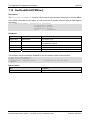
4.3
25/121
Using Visual Basic 3.0/4.0 (16 bit)
For Visual Basic 3.0/4.0 16 Bit we have created the file CIFDEF.BAS. This
file includes all the necessary definitions to access a communication device by the 16 Bit windows
DLL CIFWINDL.DLL.
4.4
Writing an own Driver or Library
To write an own driver or function library, we provide the dual port memory structures in the file
DUALPORT.H and the general definitions RCS_USER.H for the operating system (RCS) which is
running on the communication device.
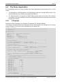
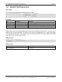
4.5
Using the Source Code
Sometimes it is not possible to use the given libraries. Mainly by using real-time DOS
environments or other operating systems like Linux, QNX or VxWorks. Therefore we providing the
whole source code in the CIF_DPM.C file. This file is used to generate the libraries and DLLs for
DOS and Windows. To determine the type of generation, the file includes three definitions
(_WINDLL, DRV_WIN and DRV_DOS).
Definition
Description
_WINDLL
Create a Windows 3.xx DLL
- Define APIENTRY and EXPORT for the calling convention
of DLL functions.
- Generate a LibMain() function as the standard DLL entry
point
- Use the Windows 3.xx function GetTickCount() to read the
system time.
DRV_WIN
Used in conjunction with _WINDLL
- Use Windows 3.xx DPMI (DOS protected mode) function to
map the dual ported memory address of the hardware.
DRV_DOS
Create a standard DOS library or object file
Windows 3.xx DLL (CifWinDl.DLL )
- Use the given physical hardware address to access the
dual ported memory.
- Use ( (clock()*1000L)/CLOCKS_PER_SEC ) to calculate
the actual system time.
Table 6: Using the Source Code
CIF Device Driver | Windows
DOC030501DRV14EN | Revision 14 | English | 2013-02 | Released | Public
© Hilscher, 1996-2013
The Device Driver
5
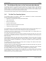
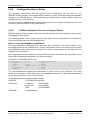
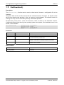
The Device Driver
IMPORTANT NOTE:
5.1
26/121
Windows® is not a deterministic real-time operating system. Any response
times to specific hardware or driver functions can not be guaranteed and
may differ between different versions of the Windows® operating systems.
Furthermore, response times are also depending on the used host
hardware, host performance, running services and installed software
components.
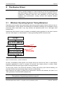
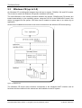
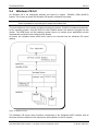
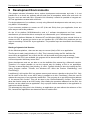
Windows Operating System Timing Behaviour
Depending on the system layout and system load the processing speed of driver calls are more or
less deterministic. Under specific circumstances the Windows operating will re-schedule running
processes which could lead to very long function call durations (factor 10 to 100 higher than
average time).
Researching this behavior shows a possible re-scheduling during transition of the driver function
call from “User-Space” to “Kernel-Space” or during processing the IRP in kernel mode.
Figure 9: Cif Device Driver – System Architecture
At least, re-scheduling could appear at all stages during the call into the driver. A User-Space,
important applications is able to increase its process and thread priority to achieve better
performance and lower the impact of other running processes.
At driver level, some of the CIFX API functions, usually used during cyclic device handling, are
executed directly at pre-processing stage to prevent re-scheduling.
Both measures are helpful in getting more deterministic function call durations, but there is no
100% guarantee of a deterministic program flow.
Note:
Specially handled CIF API functions are marked in function overview table of chapter
The Application Programming Interface on page 82.
CIF Device Driver | Windows
DOC030501DRV14EN | Revision 14 | English | 2013-02 | Released | Public
© Hilscher, 1996-2013
The Device Driver
27/121
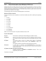
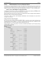
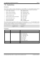
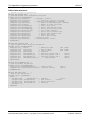
Access Time Measurements:
Test System
Windows 7 / 64Bit, Intel Core2Duo E6550 2,33 GHz 1 GB RAM
Process Priority
NORMAL_PRIORITY_CLASS
Thread Priority
THREAD_PRIORITY_TIME_CRITICAL
I/O - Cycles
100000, cycle time 1ms
CIFX Device
CIF50-PB (PBCombi V1.208 / Slave: CB-AB32 (2 Bytes In/Out))
Figure 10: Windows 7 64 Bit with standard IOCTL Handling
Figure 11: Windows 7 64 Bit with direct IOCTL Handling
CIF Device Driver | Windows
DOC030501DRV14EN | Revision 14 | English | 2013-02 | Released | Public
© Hilscher, 1996-2013
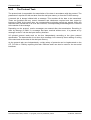
The Device Driver
5.2
28/121
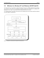
Windows 9x, Windows NT and Windows 2K/XP/Vista/7/8
The device drivers, also known as VxD (virtual device drivers) or WDM (Windows Driver Model),
are running in the kernel of multitasking operating systems like Windows 9x, Windows NT,
Windows 2K, XP, Vista, 7 and 8 and offers the best performance for drivers.
The following section describes the internal driver handling and new functions specially designed
for some SoftPLC requirements.
Figure 12: Windows 9x, Windows NT and Windows 2K/XP/Vista/7/8
CIF Device Driver | Windows
DOC030501DRV14EN | Revision 14 | English | 2013-02 | Released | Public
© Hilscher, 1996-2013
The Device Driver
29/121
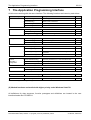
Function Overview:
!
Handles one to four communication boards at once
!
Interrupt and polling mode useable for each board (except PCMCIA)
The device drivers for Windows 9x, Windows NT and Windows 2K/XP/Vista/7/8 can handle up to
four communication boards.
All boards can be run in interrupt or polling mode. If interrupt mode is configured for a board the
device driver will install an interrupt service function for this board. The driver will install an own
interrupt service function for each interrupt driven board. So the boards can be handled
independently.
The difference between interrupt and poll mode is only the handling of application request during
timeout situations. If an application has to wait for a function (e.g. DevReset()) so in interrupt
mode the application will be blocked in the driver and the CPU is free to do other work. After the
given timeout or at the end of the command, the application is released and does normal
executing.
In poll mode the driver will run a "while loop", waiting until the function has finished or the given
timeout is reached. The user can also use the functions without timeout (timeout=0) and run the
polling by itself.
It is possible to use independent processes for send message (DevPutMessage()), receive
message (DevGetMessage()) and I/O data transfers (DevExchangeIO()). Each process will be
blocked
in
the
driver
when
necessary
without
blocking
the
other
ones.
If threads are used and a function has to wait for a certain operation ( timeout parameter unequal
0), the driver blocking mechanism will block each thread which is accessing the driver. This is by
design, because all threads in a process are sharing the same driver handle (hidden in the driver
API DLL).
A solution is to use timeout=0 in the driver functions and to check the return values if the function is
processed without an error. For the message transfer functions (DevPutMessage() and
DevGetMessage()), DevGetMBXState() can be used to check if the function can be e executed.
immediately.
On each board only one receive (DevGetMessage()), one send (DevPutMessage()) and one
IO-Exchange (DevExchangeIO()) command can be active at the same time, because there is no
command queuing in the driver implemented. So if one command for the specific function is active,
all further commands to the same function will be returned with an error. All other driver functions
are reentrant and can be called at every time.
Notice:
Switching between pooling mode and interrupt mode is supported by the driver setup
program (DrvSetup)
CIF Device Driver | Windows
DOC030501DRV14EN | Revision 14 | English | 2013-02 | Released | Public
© Hilscher, 1996-2013
The Device Driver
5.2.1
30/121
Contents for Windows 9x, NT and 2K/XP/Vista/7/8
Directory
Sub Directories
Description
DRVPRG
API \ 32Bit
Application Programming Interface, libraries and header files to access the 32
Bit driver interface DLL (the DLL is installed by the driver installation)
API \ 64Bit
Application Programming Interface, libraries and header files to access the 64
Bit driver interface DLL (the DLL is installed by the driver installation)
DEMO
C: Simple Message and IO data transfer source code example (Demo.c)
MSG_DBG: Complete CIF device driver test program written in C++, created
with Microsoft Visual C/C++ 6.0
VBasic32: Visual basic demo program created with Microsoft Visual Basic 4.0 32
bit
HEADER
C header files for the various fieldbus systems
MANUALS
Device driver manual and all protocol interface manuals
FMS_DEMO
Simple 32 bit console application to demonstrate a send and receive message
for the PROFIBUS-FMS protocol
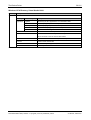
Table 7: Directory Structure
Windows 9x, Windows NT, Windows 2K/XP/Vista/7/8 API files:
CIF32DLL.DLL
Dynamic link library of the driver interface, created for use with Windows
9x, Windows NT and Window 2K/XP/Vista/7/8
(CIF95DLL.DLL/.LIB and CIFNTDLL.DLL/.LIB are only used for
compatibility with older user applications and only available for Win9x and
NT anymore)
CIF32DLL.LIB
Definition file containing the exported function of the CIF32DLL.DLL.
CIFUSER.H
Header file containing the CIF driver user interface definition.
STDINT.H
ISOC99 header file containing standard data type definitions
Device Driver files:
CIFDEV.VXD
CIF Device driver for Windows 9x
CIFDRV.SYS
CIF Device driver for Windows NT or Windows 2000/XP/Vista/7/8
Applications:
DrvSetup.EXE
CIF Device Driver Setup program for registry entries
Msg_dbg.EXE or DrvTest.EXE
CIF Device Driver Test program to run the various
device driver functions
Development platform:
Windows 9x / NT4
Microsoft Visual C++, V 6.x
Windows 2K/XP/VISTA/7/8
Microsoft Visual C++, V 6.x or above
Attention: The CIF Device Driver DLL and the driver files are installed during the driver installation
and not included in the development directories.
CIF Device Driver | Windows
DOC030501DRV14EN | Revision 14 | English | 2013-02 | Released | Public
© Hilscher, 1996-2013
The Device Driver
5.2.2
31/121
Installation of the Device Driver
The device driver will be installed by an installation program. This will guide you to the installation
process. The installation program will run the following steps:
!
Creating the standard registry entries for the CIF Device Driver
!
Copying the device driver and interface DLL files
!
Copying the device driver setup and test program
5.2.2.1
Standard Registry Entries Windows 9x and Windows NT
Windows 9x registry path:
\HKEY_LOCAL_MACHINE\System\CurrentControlSet\Services\VxD\
Windows NT registry path:
\HKEY_LOCAL_MACHINE\SYSTEM\CurrentControlSet\Services\
CIF Device Driver entry:
CIFDEV - PCISupport
\ Board0
\ Board1
\ Board2
\ Board3
0x00000000
// Enable PCI support
The default entries are:
Board0
Board1
Board2
Board3
Note:
-
BUSType
DPMBase
DPMSize
IRQ
PCIIntEnable
BUSType
DPMBase
DPMSize
IRQ
PCIIntEnable
BUSType
DPMBase
DPMSize
IRQ
PCIIntEnable
BUSType
DPMBase
DPMSize
IRQ
PCIIntEnable
0x00000000 // ISA, PCI, PCMCIA
0x000ca000 // physical dual port address
0x00000002 // DPM size in KBytes
0x00000000 // interrupt of the board
0x00000000 // PCI interrupt enabled
0x00000000 // not assigned
0x00000000
0x00000000
0x00000000
0x00000000
0x00000000 // not assigned
0x00000000
0x00000000
0x00000000
0x00000000
0x00000000 // not assigned
0x00000000
0x00000000
0x00000000
0x00000000
All entries under the key CIFDEV which are not described here, are created
automatically by the used operating system and should not be changed. To show the
entries you can use the system program REGEDIT.EXE (located in the Windows
9x\system or Windows NT\system32 directory).
CIF Device Driver | Windows
DOC030501DRV14EN | Revision 14 | English | 2013-02 | Released | Public
© Hilscher, 1996-2013
The Device Driver
5.2.2.2
32/121
Standard Registry Entries Windows 2K/XP/Vista/7/8
Windows 2K/XP/Vista/7/8 registry path:
\HKEY_LOCAL_MACHINE\SYSTEM\CurrentControlSet\Services\
CIF Device Driver entry:
CIFDEV - PCIIntEnable
\ Board0
\ Board1
\ Board2
\ Board3
0x00000000
// Enable PCI interrupt
The default entries are:
Board0
Board1
Board2
Board3
- DevActive
// Device avtive
- DevBUSType
// Bus type (1=ISA,4=PCI,5=PCMCIA)
- DevErrorDriver
// Driver error
- DevErrorRCS
// RCS error
- DevIRQVector
// System IRQ vector
- DevInfoDeviceNumber
// Device number
- DevInfoSerialNumber
// Device serial number
- DevInfoFirmwareName
// Firmware name
- DevInfoFirmwareDate
// Firmware date
- DPMBase
// Physical DPM address
- DPMSize
// DPM size in bytes
- IRQ
// IRQ
- PCIError
// PCI error
- PCIBurstLength
// PCI burst length (n.c.)
- PCIBusNumber
// PCI bus number
(n.c.)
- PCISlotNumber // PCI slot number
(n.c.)
Note:
All entries under the key CIFDEV which are not described here, are created
automatically by the used operating system and should not be changed. To show the
entries you can use the system program REGEDIT.EXE
(Windows\system32
directory).
CIF Device Driver | Windows
DOC030501DRV14EN | Revision 14 | English | 2013-02 | Released | Public
© Hilscher, 1996-2013
The Device Driver
5.2.2.3
33/121
Driver File Installation
Device Driver Files:
!
Windows 9x
The driver file CIFDEV.VXD is copied to %System Root%\System directory.
!
Windows NT
The driver file CIFDRV.SYS is copied to
%System Root%\System32\drivers directory.
!
Windows 2000 and later
The driver file CIFDRV.SYS is copied to
%System Root%\System32\drivers directory.
Device Driver Interface DLLs:
!
Windows 9x
The driver DLL CIF32DLL.DLL is copied to the
%System Root%\System directory.
!
Windows NT
The driver DLL CIF32DLL.DLL is copied to the
%System Root%\System32 directory.
!
Windows 2000 and later
The driver DLL CIF32DLL.DLL is copied to the
%System Root%\System32 directory.
Device Driver Utilities:
!
Installation path
<System>\Program Files\CIF Device Driver
!
DrvSetup
Driver setup program
!
MSG_DBG or DrvTest Driver test program
!
INF files
Hardware description for PnP OS installation
CIF Device Driver | Windows
DOC030501DRV14EN | Revision 14 | English | 2013-02 | Released | Public
© Hilscher, 1996-2013
The Device Driver
5.2.2.4
34/121
Driver Utilities
The driver including a driver setup (DRVSETUP.EXE) and a driver test (MSG_DBG.EXE or
DRVTEST:EXE) program. These files are also installed during the installation procedure.
Therefore, the installation program creates a CIF Device Driver directory below the standard
PROGRAM directory where the files are copied. Also a program folder CIF Device Driver is
created.
For the PnP operating systems Windows 9x and Windows 2K/XP/Vista/7/8, additional directories
are generated below the CIF Device Driver directory. These directories are holding the INF files
which are necessary to install hardware.
5.2.2.5
Device Driver startup
Non PnP device drivers are loaded during system start. During the startup phase, the drivers are
reading the configuration data about ISA, PCI and PCMCIA boards from the registry database of
the operating system.
The drivers for Windows 2000 and later are fully Plug and Play aware and started as soon as a
supported hardware is detected by the operating system.
CIF Device Driver | Windows
DOC030501DRV14EN | Revision 14 | English | 2013-02 | Released | Public
© Hilscher, 1996-2013
The Device Driver
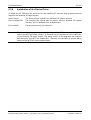
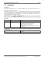
5.2.3
35/121
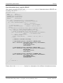
Configure the Windows 9x and Windows NT Driver
The user must configure the physical memory address, the size of the DPM and the interrupt
number of each communication board.
All these information are written to the registry data base of the operating system. To get an easy
access to this data the device driver gets its own setup program DRVSETUP.EXE. This program
will help you to change the registry entries without using REGEDIT.EXE. It is also used during
installation to configure the communication boards for the first time and it will be copied to your
hard disk drive for further use. The program is able to determine the Windows platform and show
this in the caption line of the program.
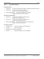
Figure 13: Configuration Window – Windows 9x and NT
Parameter
Description
DPM base address
Physical memory address of the device.
A0000 to FF000 in 2 KBytes steps.
( CA000, CA800, CB000......)
Physical dual port memory size given in Kbytes. If no entry is defined, the driver uses
2 KBytes as default.
DPM size
NONE = Board not configured
2 KByte = 4096 bytes
8 KByte = 8192 bytes
Interrupt number
Physical interrupt number.
NONE = Board not configured
POLLING = Driver does not use interrupts
(3, 4, 5, 6, 7, 9, 10, 11, 12, 14, 15)
Table 8: Configuration Window – Windows 9x and NT
Notice:
Compare the settings you made with the actual jumper settings of the communication
board. Invalid entries in the registry, forces the driver to unload itself.
CIF Device Driver | Windows
DOC030501DRV14EN | Revision 14 | English | 2013-02 | Released | Public
© Hilscher, 1996-2013
The Device Driver
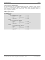
5.2.4
36/121
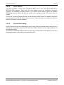
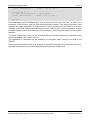
Configure the Driver under Windows 2K and later
Windows 2K/XP/Vista/7/8 are Plug and Play operating systems. The device settings are done with
the Device Manager. PnP devices like PCI and PCMCIA, will be recognized by the operating
system, when they inserted in the PC. The Device Manager from Windows will ask for a INF file,
which describes the hardware. These files can be found either on the System Software CD
(directory Driver\Win_2K_XP_VISTA_7_8) or after running the driver setup program in the <Install
Directory>\CIF Device Driver\Win2000_XP_VISTA_7_8.
ISA devices must be inserted manually by the use of the hardware Wizard. An INF file is also
necessary and can be found at the above described places.
The driver setup program (DRVSETUP.EXE) for Windows 2K/XP/Vista/7/8 only gives the
possibility to global enable or disable interrupt handling for all PCI boards. All other settings must
be done by the use of the Device Manager and the Hardware Wizard.
Figure 14: Configuration Window – Windows 2K and later
Notice:
For ISA devices you have to make sure the hardware jumper setting corresponds to
the software setting. Invalid or different settings can result in undefined system
behavior.
CIF Device Driver | Windows
DOC030501DRV14EN | Revision 14 | English | 2013-02 | Released | Public
© Hilscher, 1996-2013
The Device Driver
5.2.5
37/121
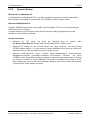
System Startup
Windows 9x and Windows NT:
On Windows 9x and Windows NT PCs, you have to restart the system to load the device driver.
Each change to the setting of a device (ISA, PCI, PCMCIA) needs a system restart.
Windows 2000/XP/Vista/7/8:
Windows 2000/XP doesn't need a restart after driver installation. The driver will be automatically
loaded if a device is installed.
A system restart is only necessary if either the PCI interrupt setting (polling/interrupt) or the
settings of an ISA device is changed.
Startup Information:
!
Windows 9x: The driver will show the following lines at system
CIF Device Driver Release V x.xxx After the restart the driver is ready to work.
!
Windows NT: Change to the <Control panel> and open <devices>, this should show
"CIFDEV started system". You can check the correct installation of the driver by running NT
diagnosis 'drivers'. After the restart the driver is ready to work
!
Windows 2K/XP/Vista/7/8: Open <Control Panel><Administrative Tool><Computer
Management><System Information><Software Environment> <Drivers>. The driver
"CIFDEV" will be shown either running or stopped. It should be in the state running, if at least
one device is installed. A second indication if the driver is installed and running is a CIF
device without any errors in the Device Manager. Because only devices which are accepted
by driver will be shown without any errors.
CIF Device Driver | Windows
DOC030501DRV14EN | Revision 14 | English | 2013-02 | Released | Public
start:
© Hilscher, 1996-2013
The Device Driver
5.3
38/121
Windows CE (up to 5.0)
On Windows CE we distinguish between three drivers to support PCMCIA, ISA and PCI boards.
This is done to match the Windows CE specific conditions to the best.
The main difference is the startup procedure between the drivers. PCMCIA and PCI drivers are
loaded automatically, by the operating system, using the PnP-ID of the PCMCIA/PCI board if the
device is plugged into the system. ISA driver can be loaded at system start or at runtime by an
application.
All drivers are loadable drivers which must not be included into the Windows CE kernel (binary).
Figure 15: Windows CE
The Windows CE device driver interface corresponds to the Windows 9x/NT interface and all
functions which are defined in this manual are also available on the CE system.
CIF Device Driver | Windows
DOC030501DRV14EN | Revision 14 | English | 2013-02 | Released | Public
© Hilscher, 1996-2013
The Device Driver
39/121
Features:
!
ISA driver handles up to four communication board
!
PCI driver handles up to four communication board
!
PCMCIA driver handles one communication board
!
Loadable driver, which does not need to be included into the Windows CE kernel
!
Complete source code for the drivers, interface DLL and programs
Limitations:
!
No interrupt functionality included yet
!
PCMCIA, ISA and PCI driver are not able to run at the same time
Development platform:
Windows CE 3.0
Embedded Visual Tools 3.0
Windows CE 4.0/5.0
Embedded Visual C/C++ 4.0
CIF Device Driver | Windows
DOC030501DRV14EN | Revision 14 | English | 2013-02 | Released | Public
© Hilscher, 1996-2013
The Device Driver
5.3.1
40/121
General Information about Windows CE Drivers
Windows CE drivers are DLLs which must meet some special requirements. A driver must offer a
specific interface to be accessible by the operating system. Windows CE uses a three letter prefix
to distinguish between different drivers. The information about the driver prefix and the name of the
driver file must be defined in the registry.
This information will be used by the operating system to call a driver.
Windows CE Driver Interface:
Following functions must be available in a the driver interface and will be called by the operating
system:
!
xxx_Init
!
xxx _Deinit
!
xxx _Open
!
xxx _Close
!
xxx _Read
!
xxx _Write
!
xxx _Seek
!
xxx _PowerDown
!
xxx _PowerUp
!
xxx _IOControl
Where xxx is the driver prefix. The prefix for Hilscher drivers is CIF.
Function Description:
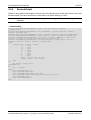
CIF_Init
This function is called by the Device Manager to initialize a driver.
CIF_Deinit
When the user stops using a device the Device Manager calls this function.
The function frees all virtual memory that was allocated during the install
step.
CIF_Open
This function opens a device for reading and/or writing. An application
indirectly invokes this function when it calls CreateFile to open a CIF
device. The function creates a new device context information structure.
CIF_Close
Is called when an application calls CloseHandle(hFile) to stop using a
stream interface driver. It also removes an open context from the linked list
and frees this context.
CIF_Read, CIF_Write, CIF_Seek (not supported)
Standard interface for ReadFile and WriteFile functions. This is not
supported by the CIF driver.
Continued on next page
CIF Device Driver | Windows
DOC030501DRV14EN | Revision 14 | English | 2013-02 | Released | Public
© Hilscher, 1996-2013
The Device Driver
41/121
CIF_PowerDown, CIF_PowerUp
Are used to manage power management events from the perating system.
These functions have an empty body and are not used by CIF driver.
CIF_IOControl
5.3.2
This function sends a command to a device when an application uses the
DeviceIOControl function to specify an operation to be performed. All CIF
functions are processed by DeviceIOControl function.
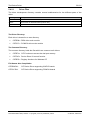
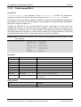
Contents for Windows CE
The Windows CE driver will be delivered in source code. This includes the drivers, the driver
interface DLL (API DLL), test and demo programs and the development projects files for all parts.
Also included are C header files with the driver function and protocol definitions for own
applications and the protocol and driver manuals in PDF format.
The following table shows the contents of the \DRVPRG directory.
DEVDRV
Directory
Description
Manuals
Protocol and driver manuals in .PDF file format
Headers
Protocol definition files
CE5
CEDRVx.xxx
Directory
Subdirectory
Description
Application
CifTest
Driver test program (CIFTEST.EXE)
DrvSetup
Driver setup program (DRVSETUP.EXE)
IODemo
Simple I/O demo program (IODEMO.EXE)
Common
Common files for the applications
CifISA
Device driver for ISA boards (CIFISA.DLL)
CifPCC
Device driver for PCMCIA boards (CIFPCC.DLL)
CifPCI
Device driver for PCI boards (CIFPCI.DLL)
Common
Common driver include files
CifCEDll
CifDrv
Include
Device driver interface DLL (CIFCEDLL.DLL)
Include directory for applications, holds the definition file
CIFUSER.H
Table 9: Directory Structure
CIF Device Driver | Windows
DOC030501DRV14EN | Revision 14 | English | 2013-02 | Released | Public
© Hilscher, 1996-2013
The Device Driver
5.3.2.1
42/121
Driver Files
The driver development directory contains several subdirectories for the different parts of the
driver.
Directory
Subdirectory
Description
CifDrv
CifISA
Device driver for ISA boards (CIFISA.DLL)
CifPCC
Device driver for PCMCIA boards (CIFPCC.DLL)
CifPCI
Device driver for PCI boards (CIFPCI.DLL)
Common
Common driver include files
Table 10: Driver Files
The Driver Directory:
Each driver is located in an own directory.
!
CIFISA.c
ISA driver main module
!
CIFPCI.c
PCI driver main module
!
CIFPCC.c PCIMCIA driver main module
The Common Directory:
The common directory holds the files which are common to all drivers.
!
CIFDEV.c CIF-Functions to access the dual port memory
!
CIFFNC.c Device Driver IO control function
!
CIFREG.c Registry functions for Windows CE
File Names after Compilation:
CIFISA.DLL
CIF Device Driver supporting ISA boards
CIFPCI.DLL
CIF Device Driver supporting PCI boards
CIFPCC.DLL
CIF Device Driver supporting PCMCIA boards
CIF Device Driver | Windows
DOC030501DRV14EN | Revision 14 | English | 2013-02 | Released | Public
© Hilscher, 1996-2013
The Device Driver
5.3.2.2
43/121
Application Interface Files
The application interface to the driver is a DLL (CIFCEDLL.DLL). The source of the DLL is located
in the CifCEDLL directory. The DLL converts function calls from the CIF driver API into
DeviceIOControl function calls to the driver.
Directory
Description
CifCEDll
Device driver interface DLL (CIFCEDLL.DLL)
Table 11: Application Interface Files
CifCEDLL Source Files:
!
CifCEDLL.c
User interface module
!
CifDown.c
Download functions for configuration and firmware download
File Names after Compilation:
CIFCEDLL.DLL
5.3.2.3
CIF Device Driver application interface DLL (API)
Setup, Test and Demo program
Each of the programs has an own subdirectory. Common files for all applications are located in the
common subdirectory.
The applications are dialog based programs and as far as possible, each dialog is based in an own
source module. Module names comparing to the function they processes.
Directory
Subdirectory
Description
Application
CifTest
Driver test program (CIFTEST.EXE)
DrvSetup
Driver setup program (DRVSETUP.EXE)
IODemo
Simple I/O demo program (IODEMO.EXE)
Common
Common files for the applications
Table 12: Setup, Test and Demo Files
Dependencies:
CifCEDLL.LIB
CIF driver interface DLL
CIFUSER.H
CIF driver interface definition file
CIF Device Driver | Windows
DOC030501DRV14EN | Revision 14 | English | 2013-02 | Released | Public
© Hilscher, 1996-2013
The Device Driver
44/121
5.3.3
Compiling the Source Code
Note:
All drivers and applications must be compiled before they can be used.
Microsoft has divided the development process for Windows CE systems into two parts. One part
is the generation of a running hardware platform using the Windows CE operating system while the
other part focuses the application development for an existing Windows CE system. Both parts are
using different environments. Platforms are generated with the Microsoft Platformbuilder and the
application development is based on the Microsoft Embedded Visual Tools.
There is one important dependency between the two parts. Application development requires
information about the target system like used CPU, available system drivers, available system
services and platform depending libraries and definition files. These information’s are only
available in the platform generation process. The only way to get the information into the
application development process is a platform SDK (Software Development Kit) which must be
generated by the Microsoft Platformbuilder.
Because of the above described development process, it is not possible to offer pre-compiled
drivers and application for a specific Windows CE target system.
This chapter describes the steps to compile the source code.
!
Install the Platform SDK for the target system
!
Include the installed Platform SDK into the existing project
!
Compile the driver, API, setup and test programs
5.3.3.1
Install the Platform SDK for the target system
Platform SDKs are generated by the Microsoft Platformbuilder and installable like a normal
program. Make sure the Microsoft Embedded Visual Tools are already installed.
CIF Device Driver | Windows
DOC030501DRV14EN | Revision 14 | English | 2013-02 | Released | Public
© Hilscher, 1996-2013
The Device Driver
5.3.3.2
45/121
Include the installed Platform SDK into an existing project
New installed Platform SDKs are not automatically included into existing projects. There are
different ways to insert a new SDK into a project. Microsoft has described the procedure under
Q266243.
The following point will give you an overview how to proceed:
1.
Build a new project in the Microsoft Embedded Visual Tools. This enables the access to
already installed SDKs. This procedure is not preferred, because you have to set all project
dependencies according to the original project by yourself.
2.
Extend the original project by inserting a DUMMY project (preferred method). After inserting
a dummy project it is possible to extend the existing project by the new settings from the
dummy project.
!
Add a dummy project with the necessary CPUs (hardware) to the existing project
!
Select the dummy project and make it the active project
!
Select the hardware you want to insert into the original project
!
Open the configuration dialog from <Build->Configuration...>
!
Now you see both projects, the original one and the new created one with their
configurations where the original one does not have any assigned configuration.
!
Select the original project and choose <ADD> and you are able to add the
CPUs (Debug/Release) supported by the dummy project.
!
Save the project
!
At the end you can delete the dummy project
5.3.3.3
Compile the driver, API, Setup and Test programs
Each part has an own project file. After loading the project file the specific project can be compiled
in debug or release version. Some of the projects using specific settings which will be shown in the
following table.
CIF Device Driver | Windows
DOC030501DRV14EN | Revision 14 | English | 2013-02 | Released | Public
© Hilscher, 1996-2013
The Device Driver
46/121
Specific Project Settings:
CIF Driver Interface DLL
Project File
Description
Settings
CifCEDLL
CIF driver API
Preprocessor definitions:
CIFCEDLL_EXPORTS
Additional include directories:
..\CIfDRV\Common
CIF Device Driver
Project File
Description
Settings
CifISA
ISA card driver
Preprocessor definitions:
CIFISA_EXPORTS
Additional include directories:
..\common
CifPCC
PCMCIA driver
Preprocessor definitions:
CIFPCC_EXPORTS
Used in CIFDEV.H to Includes PCMCIA specific files (TUPLE.H and
CARDSERV.H) and data areas into structure DEV_INSTANCE.
Additional include directories:
..\common
Object/library modules:
pcmcia.lib
Windows CE library file for PCMCIA specific functions
Windows CE system header files:
tuple.h
cardserv.h
devload.h
CifPCI
PCI driver
Preprocessor definitions:
CIFPCI_EXPORTS
Used in CIFDEV.H to Includes PCI specific files (CIFPCI.H) and data areas into
structure DEV_INSTANCE.
Additional include directories:
..\common
CIF Driver Programs
Project File
Description
Settings
DrvSetup
Driver setup
program
Additional include directories:
..\common
..\..\include
..\..\CifDRV\common
Object/library modules:
CifCEDLL.lib
Interface API LIB file (release/debug)
CEDDK.lib
Windows CE library file for operating system specific functions
MSG_DBG
CIF test program
Additional include directories:
..\common
..\..\include
Object/library modules:
CifCEDLL.lib
Interface API LIB file (release/debug)
IODemo
I/O demo program
Additional include directories:
..\common
..\..\include
Object/library modules:
CifCEDLL.lib
Interface API LIB file (release/debug)
CIF Device Driver | Windows
DOC030501DRV14EN | Revision 14 | English | 2013-02 | Released | Public
© Hilscher, 1996-2013
The Device Driver
5.3.4
47/121
Installation of the Device Driver
To install the CIF Device Driver, the driver file, the interface DLL and the utility programs must be
copied to the Windows CE target system.
Device Driver
The driver must be copied to the Windows CE system directory
Driver interface DLL
The interface DLL should also be placed into the Windows CE system
directory, so it is reachable from all applications
Driver utilities
Can be placed in any user directory
Note:
The executable programs are written by the use of the MFC and compiled with the
option "Use MFC as a static Library", so it should not be necessary to have a MFC.DLL
on the Windows CE target system. The debug version of the programs are compiled
with the option "Use MFC in a Shared DLL". Therefore it is necessary to put the debug
version of the MFC DLL on the target system.
CIF Device Driver | Windows
DOC030501DRV14EN | Revision 14 | English | 2013-02 | Released | Public
© Hilscher, 1996-2013
The Device Driver
5.3.5
48/121
Configure the Device Driver
The standard configuration and the specific board configuration can be done by the
DRVSETUP.EXE program. The program offers functions to create, show and change the hardware
settings for the different drivers. It also generates the standard driver registry entries to allow the
operating system to load the driver.
If a driver should be loaded from the system during start time, the registry settings and driver and
the API file must be included in the system binary.
5.3.5.1
PCMCIA Initialization Process and Registry Entries
PCMCIA cards are Plug and Play aware and automatically detected by the operating system if they
are plug into the system.
The operating system uses a registry entry to know which driver is responsible for the hardware.
This entry must be placed into the following entry:
[HKEY_LOCAL_MACHINE][Drivers][PCMCIA]
The entry contains the manufacture, the card type and a checksum. This must compare to the
information stored on the PCMCIA card. The only configuration value for the driver is the memory
size (DPMSize) because this can’t be detected. The memory start address can be taken from the
Windows CE card services.
After mapping the memory window into system ram the driver also checks the accessibility of the
memory and activates the hardware if the check successful.
Example for a PROFIBUS CIF60 card:
Hilscher_GmbH-CIF60_PB-CE0C
Index:
1
Prefix:
"CIF"
DLL:
"CIFPCC.DLL"
DeviceType:
3
DPMSize:
8
//
//
//
//
//
//
Card identification
Dword
String
String
Dword
Dword
The card identification contains the manufacture, a device name and a checksum. The other
entries are necessary to define which driver is responsible for this device. This driver will be started
by the operating system if such a card is found.
The following boards are defined at the moment:
CIF60-PB
PROFIBUS DP and FMS
CIF60-CAN
CAN open
Device Net
SDS
CIF60-IBM
InterBus Master
(CIF60-COM)
(CIF60-DNM)
(CIF60-SDSM)
CIF Device Driver | Windows
DOC030501DRV14EN | Revision 14 | English | 2013-02 | Released | Public
© Hilscher, 1996-2013
The Device Driver
49/121
Using of the Driver Setup Program:
Run the device driver setup program DRVSETUP.EXE to create the PCMCIA entries. Therefore
you have to go to the menu point <Registry> <Create PCMCIA entries>. With the create button, all
of the following entries will be created. To remove the entries use the delete button. There is no
further configuration necessary.
PCMCIA registry entries:
HKEY_LOCAL_MACHINE:
Drivers
PCMCIA
Hilscher_GmbH-CIF60_PB-CE0C
Index:
1
Prefix:
"CIF"
DLL:
"CIFPCC.DLL"
DeviceType:
3
DPMSize:
8
PCMCIA
Hilscher_GmbH-CIF60_CAN-8E6F
Index:
1
Prefix:
"CIF"
DLL:
"CIFPCC.DLL"
DeviceType:
3
DPMSize:
8
PCMCIA
Hilscher_GmbH-CIF60_IBM-0761
Index:
1
Prefix:
"CIF"
DLL:
"CIFPCC.DLL"
DeviceType:
3
DPMSize:
8
//
//
//
//
//
Dword
String
String
Dword
Dword
// Dword
// String
// String
// Dword
// Dword
//
//
//
//
//
Dword
String
String
Dword
Dword
CIF Device Driver | Windows
DOC030501DRV14EN | Revision 14 | English | 2013-02 | Released | Public
© Hilscher, 1996-2013
The Device Driver
5.3.5.2
50/121
ISA Initialization Process and Registry Entries
ISA cards are not Plug and Play aware. Therefore the information about installed ISA cards must
be provided by the user and will be inserted into the registry. During CIF_init() the driver reads the
configuration for “Board 0..3“ from the registry entry.
[HKEY_LOCAL_MACHINE][Drivers][BuiltIn][CIFDEV]
Configuration values are the memory size (DPMSize), the memory start address (DPMBase) and
an interrupt number (IRQ) which is ignored. After checking the values the driver allocates the
memory area and tries to access the hardware.
If the driver is able to read a valid hardware identification from the hardware, the card will be
accepted and activated.
Using of the Driver Setup Program:
Run the device driver setup program DRVSETUP.EXE to create the default registry entries for ISA
boards. Therefore, go to the menu point <Registry> <Create ISA entries> and use the create
button to create the standard entries, shown below. Use the delete button to remove all ISA entries
from the registry.
Afterwards, change to <ISA/PCI bus> <Board setup> to configure each ISA board independently.
Registry entries:
HKEY_LOCAL_MACHINE:
Drivers
BuiltIn
CIFDEV
Index
Order
Prefix
DLL
DeviceType
PCISupport
1
3
"CIF"
"CIFISA.DLL"
0
0
Board0
BUSType
DPMBase
DPMSize
IRQ
PCIIntEnable
Board1
BUSType
DPMBase
DPMSize
IRQ
PCIIntEnable
Board2
BUSType
DPMBase
DPMSize
IRQ
PCIIntEnable
Board3
BUSType
DPMBase
DPMSize
IRQ
PCIIntEnable
//
//
//
//
//
//
Dword
Dword
String
String
Dword
Dword
0
000CA000
2
0
0
//
//
//
//
//
Dword
Dword
Dword
Dword
Dword
0
00000000
0
0
0
//
//
//
//
//
Dword
Dword
Dword
Dword
Dword
0
00000000
0
0
0
//
//
//
//
//
Dword
Dword
Dword
Dword
Dword
0
00000000
0
0
0
//
//
//
//
//
Dword
Dword
Dword
Dword
Dword
CIF Device Driver | Windows
DOC030501DRV14EN | Revision 14 | English | 2013-02 | Released | Public
© Hilscher, 1996-2013
The Device Driver
5.3.5.3
51/121
PCI Initialization Process and Registry Entries
PCI cards are also Plug and Play aware and detected by the operating system. This is done during
the startup phase of Windows CE and the operating system also assigns the resources requested
by the PCI hardware.
The PCI driver expects the hardware configuration information under the following registry key.
[HKEY_LOCAL_MACHINE][Drivers][BuiltIn][CIFDEV]
This entry will be created by the driver setup program DRVSETUP.EXE. The program scans the
PCI hardware and if a Hilscher PCI hardware is found, it reads the resource values for the memory
start address (DPMBase), the memory size (DPMSize) and the interrupt number (IRQ) from the
hardware and creates the necessary entries.
Note:
Microsoft does not recommend to scan the PCI hardware directly from a driver. That’s
why the scan function is placed into a separate program.
The driver reads the configuration information during CIF_init(), checks the values, allocates the
memory area and tries to access the hardware. If the driver is able to read a valid hardware
identification from the hardware, the card will be accepted and activated.
Using of the Driver Setup Program:
Run the device driver setup program DRVSETUP.EXE to create the default registry entries for PCI
boards. Therefore, go to the menu point <Registry> <Create PCI entries> and use the create
button to create the standard entries (shown below). Use the delete button to remove all PCI
entries from the registry.
Note:
The registry entries are only created if at least one PCI Hilscher card could be found in
the system.
PCI cards are Plug and Play aware. You can check the card settings by changing to <ISA/PCI
bus> <Board setup>. It is not possible to change neither the memory address nor the memory size.
CIF Device Driver | Windows
DOC030501DRV14EN | Revision 14 | English | 2013-02 | Released | Public
© Hilscher, 1996-2013
The Device Driver
52/121
Registry entries:
HKEY_LOCAL_MACHINE:
Drivers
BuiltIn
CIFDEV
Index
Order
Prefix
DLL
DeviceType 0
PCISupport 0
1
3
"CIF"
"CIFPCI.DLL"
Board0
BUSType
DPMBase
DPMSize
IRQ
PCIIntEnable
Board1
BUSType
DPMBase
DPMSize
IRQ
PCIIntEnable
Board2
BUSType
DPMBase
DPMSize
IRQ
PCIIntEnable
Board3
BUSType
DPMBase
DPMSize
IRQ
PCIIntEnable
//
//
//
//
//
//
Dword
Dword
String
String
Dword
Dword
0
00000000
0
0
0
//
//
//
//
//
Dword
Dword
Dword
Dword
Dword
0
00000000
0
0
0
//
//
//
//
//
Dword
Dword
Dword
Dword
Dword
0
00000000
0
0
0
//
//
//
//
//
Dword
Dword
Dword
Dword
Dword
0
00000000
0
0
0
//
//
//
//
//
Dword
Dword
Dword
Dword
Dword
CIF Device Driver | Windows
DOC030501DRV14EN | Revision 14 | English | 2013-02 | Released | Public
© Hilscher, 1996-2013
The Device Driver
5.3.6
53/121
Integration into a Windows CE Image
This is an example how to integrate the driver into a Windows CE image. The example shows the
integration of the PCI driver.
5.3.6.1
Extend the Platform.reg file
Extend the Platform.reg file by the registry settings for the driver.
[HKEY_LOCAL_MACHINE\Drivers\BuiltIn\CIFDEV]
"Index"
= dword:1
"Prefix"
= "CIF"
"Orde r"
= dword:3
"Dll"
= "cifpci.dll"
“DeviceType"
= dword:0
These entries defining the PCI device driver prefix “CIF” for the functions in the CIFPCI.DLL and
the start index of the first device.
5.3.6.2
cifpci.dll
Extend ‘Module’ Section in the Project.bib File
\[DestinationPath]\cifpci.dll NK SH
“DestinationPath” defines the path to the driver file.
CIF Device Driver | Windows
DOC030501DRV14EN | Revision 14 | English | 2013-02 | Released | Public
© Hilscher, 1996-2013
The Device Driver
5.4
54/121
Windows CE 6.0
On Windows CE 6 we distinguish between two drivers to support PCMCIA, DPM (ISA/PCI)
boards. This is done to match the Windows CE specific conditions to the best.
Note:
The Windows CE 6.0 driver supports ISA and PCI cards in one driver (CIFDPM.DLL)
and it is possible to use both type of cards at the same time.
The main difference is the startup procedure between the drivers. PCMCIA is loaded automatically,
by the operating system, using the PnP-ID of the PCMCIA board if the device is plugged into the
system. The DPM driver can be loaded at system start or at runtime by an application and will
automatically handle PCI and configured ISA boards.
All drivers are loadable drivers which don't need to be included into the Windows CE kernel
(binary).
Figure 16: Windows CE 6.0
The Windows CE device driver interface corresponds to the Windows 9x/NT interface and all
functions which are defined in this manual are also available on the CE system.
CIF Device Driver | Windows
DOC030501DRV14EN | Revision 14 | English | 2013-02 | Released | Public
© Hilscher, 1996-2013
The Device Driver
55/121
Features:
!
DPM driver handles up to four communication boards (ISA and PCI)
!
ISA and PCI cards can be used at the same time
!
PCI hardware detection now down in the driver
!
PCMCIA driver handles only one communication board
!
Loadable driver, which does not need to be included into the Windows CE kernel
!
Complete source code for the drivers, interface DLL and programs
Limitations:
!
No interrupt functionality included
!
PCMCIA and DPM driver cannot be used at the same time
Development platform:
Windows CE
Microsoft Visual Studio 2005
CIF Device Driver | Windows
DOC030501DRV14EN | Revision 14 | English | 2013-02 | Released | Public
© Hilscher, 1996-2013
The Device Driver
5.4.1
56/121
General Information about Windows CE Drivers
Windows CE drivers are DLLs which must meet some special requirements. A driver must offer a
specific interface to be accessible by the operating system. Windows CE uses a three letter prefix
to distinguish between different drivers. The information about the driver prefix and the name of the
driver file must be defined in the registry.
This information will be used by the operating system to call a driver.
Windows CE Driver Interface:
Following functions must be available in a the driver interface and will be called by the operating
system:
!
xxx_Init
!
xxx _Deinit
!
xxx _Open
!
xxx _Close
!
xxx _Read
!
xxx _Write
!
xxx _Seek
!
xxx _PowerDown
!
xxx _PowerUp
!
xxx _IOControl
Where xxx is the driver prefix. The prefix for Hilscher drivers is CIF.
Function Description:
CIF_Init
This function is called by the Device Manager to initialize a driver.
CIF_Deinit
When the user stops using a device the Device Manager calls this function.
The function frees all virtual memory that was allocated during the install
step.
CIF_Open
This function opens a device for reading and/or writing. An application
indirectly invokes this function when it calls CreateFile to open a CIF
device.
The function creates a new device context information structure.
CIF_Close
Is called when an application calls CloseHandle(hFile) to stop using a
stream interface driver. It also removes an open context from the linked list
and frees this context.
CIF_Read, CIF_Write, CIF_Seek (not supported)
Standard interface for ReadFile and WriteFile functions. This is not
supported by the CIF driver.
Continued on next page
CIF Device Driver | Windows
DOC030501DRV14EN | Revision 14 | English | 2013-02 | Released | Public
© Hilscher, 1996-2013
The Device Driver
57/121
CIF_PowerDown, CIF_PowerUp
Are used to manage power management events from the perating system.
These functions have an empty body and are not used by CIF driver.
CIF_IOControl
5.4.2
This function sends a command to a device when an application uses the
DeviceIOControl function to specify an operation to be performed. All CIF
functions are processed by DeviceIOControl function.
Contents for Windows CE
The Windows CE driver will be delivered in source code. This includes the drivers, the driver
interface DLL (API DLL), test and demo programs and the development projects files for all parts.
Also included are C header files with the driver function and protocol definitions for own
applications and the protocol and driver manuals in PDF format.
The following table shows the contents of the \DRVPRG directory.
DEVDRV
Directory
Description
Manuals
Protocol and driver manuals in .PDF file format
Headers
Protocol definition files
CE6
Windows CE 6 directory
Subdirectory
Description
CEDRVx.xxx
Platform Builder Project
Table 13: Directory Structure
Windows CE 6 Directory, Platform Builder:
Directory
Description
PB
Platform Builder Project
Directory
Description
CifCEDll
Device driver interface DLL (CIFCEDLL.DLL)
CifDPM
Device driver for DPM boards (CIFDPM.DLL)
This is the driver to use for ISA and PCI boards
CifPCC
Device driver for PCMCIA boards (CIFPCC.DLL)
Common
Common driver include files
Include
Include directory for applications, holds the definition file CIFUSER.H
CIF Device Driver | Windows
DOC030501DRV14EN | Revision 14 | English | 2013-02 | Released | Public
© Hilscher, 1996-2013
The Device Driver
58/121
Windows CE 6 Directory, Visual Studio 2005:
Directory
Description
VS2005
Visual Studio 2005 Solution
Directory
Subdirectory
Description
Application
AygShell
Neccessary for MFC applications if not included in SDK
CifTest
Driver test program (CIFTEST.EXE)
DrvSetup
Driver setup program (DRVSETUP.EXE)
IODemo
Simple I/O demo program (IODEMO.EXE)
Common
Common files for the applications
CifCEDll
Device driver interface DLL (CIFCEDLL.DLL)
CifDPM
Device driver for DPM boards (CIFDPM.DLL)
This is the driver to use for ISA and PCI boards
CifPCC
Device driver for PCMCIA boards (CIFPCC.DLL)
Common
Common driver include files
Include
Include directory for applications, holds the definition file CIFUSER.H
DDK
Necessary DDK definition files
Table 14: Directory Structure
CIF Device Driver | Windows
DOC030501DRV14EN | Revision 14 | English | 2013-02 | Released | Public
© Hilscher, 1996-2013
The Device Driver
5.4.2.1
59/121
Driver Files
The driver development directory contains several subdirectories for the different parts of the
driver.
Directory
Description
CifDPM
Device driver for ISA/PCI boards (CIFDPM.DLL)
CifPCC
Device driver for PCMCIA boards (CIFPCC.DLL)
Common
Common driver include files
Table 15: Driver Files
The Driver Directory:
Each driver is located in an own directory.
!
CIFDPM.c DPM driver main module
!
CIFPCC.c PCIMCIA driver main module
The Common Directory:
The common directory holds the files which are common to all drivers.
!
CIFDEV.c CIF-Functions to access the dual port memory
!
CIFFNC.c Device Driver IO control function
!
CIFREG.c Registry functions for Windows CE
File Names after Compilation:
CIFDPM.DLL
CIF Device Driver supporting ISA/PCI boards
CIFPCC.DLL
CIF Device Driver supporting PCMCIA boards
CIF Device Driver | Windows
DOC030501DRV14EN | Revision 14 | English | 2013-02 | Released | Public
© Hilscher, 1996-2013
The Device Driver
5.4.2.2
60/121
Application Interface Files
The application interface to the driver is a DLL (CIFCEDLL.DLL). The source of the DLL is located
in the CifCEDLL directory. The DLL converts function calls from the CIF driver API into
DeviceIOControl function calls to the driver.
Directory
Description
CifCEDll
Device driver interface DLL (CIFCEDLL.DLL)
Table 16: Application Interface Files
CifCEDLL Source Files:
!
CifCEDLL.c
!
CifDown.c Download functions for configuration and firmware download
User interface module
File Names after Compilation:
CIFCEDLL.DLL CIF Device Driver application interface DLL (API)
5.4.2.3
Setup, Test and Demo Program
Each of the programs has an own subdirectory. Common files for all applications are located in the
common subdirectory.
The applications are dialog based programs and as far as possible, each dialog is based in an own
source module. Module names comparing to the function they processes.
Directory
Subdirectory
Description
Application
AygShell
Neccessary for MFC applications if not included in SDK
CifTest
Driver test program (CIFTEST.EXE)
DrvSetup
Driver setup program (DRVSETUP.EXE)
IODemo
Simple I/O demo program (IODEMO.EXE)
Common
Common files for the applications
Table 17: Setup, Test and Demo Program Files
Dependencies:
CifCEDLL.LIB
CIF driver interface DLL
CIFUSER.H
CIF driver interface definition file
CIF Device Driver | Windows
DOC030501DRV14EN | Revision 14 | English | 2013-02 | Released | Public
© Hilscher, 1996-2013
The Device Driver
61/121
5.4.3
Compiling the Source Code
Note:
All drivers and applications must be compiled before they can be used.
Microsoft has divided the development process for Windows CE systems into two parts. One part
is the generation of a running hardware platform using the Windows CE operating system while the
other part focuses the application development for an existing Windows CE system. Both parts are
using different environments. Platforms are generated with the Microsoft Platformbuilder and the
application development is based on the Microsoft Visual Studio 2005.
The Driver either includes a project for use within Platform Builder to integrate the driver directly
into your platform, or a solution to compile the driver for inclusion using non-volatile memory (e.g.
Flashdisk).
The first method can only be used to build the driver and the API dll itself. It cannot be used to
build the setup and test applications.
The second method needs a Software Development Kit (SDK) to be installed for the target device.
The following chapter describes the steps to compile the source using:
!
Microsoft Platform Builder
!
Microsoft Visual Studio 2005
CIF Device Driver | Windows
DOC030501DRV14EN | Revision 14 | English | 2013-02 | Released | Public
© Hilscher, 1996-2013
The Device Driver
5.4.3.1
62/121
Compile using Platform Builder
The Platform Builder example will include all drivers into your Windows CE runtime image. To
change the registry settings or the included files, you will need to edit "CifDrv.reg" and "CifDrv.bib"
inside the project directory. The Platform Builder project does not include the
Setup/Testapplications. These must be compiled using the Visual Studio 2005 project.
The following steps need to be done to build and integrate the driver into a runtime image:
!
Add the project to your Platfom Builder solution
CIF Device Driver | Windows
DOC030501DRV14EN | Revision 14 | English | 2013-02 | Released | Public
© Hilscher, 1996-2013
The Device Driver
!
Exclude all drivers you don't want to compile (e.g. CifPCC)
!
Comment out unneeded files from "CifDrv.bib"
!
Edit the default registry settings in "CifDrv.reg"
!
Build your platform
CIF Device Driver | Windows
DOC030501DRV14EN | Revision 14 | English | 2013-02 | Released | Public
63/121
© Hilscher, 1996-2013
The Device Driver
5.4.3.2
64/121
Compile using Microsoft Visual Studio 2005
The Visual Studio project includes the following components:
!
CifDriver and API Dll
!
Setup and Testapplications
It needs to be setup to use the target platforms SDK. You will need to adjust the platform
Configuration to be able to compile it.
Note:
If you want to build the PCMCIA driver you will need the "pcc_pcm.lib" from your
platform, thus it is excluded from build per default.
The following steps need to be done to compile the solution:
!
Add your target SDK to known configurations
!
Rebuild the project
CIF Device Driver | Windows
DOC030501DRV14EN | Revision 14 | English | 2013-02 | Released | Public
© Hilscher, 1996-2013
The Device Driver
5.4.4
65/121
Installation of the Device Driver
To install the CIF Device Driver, the driver file, the interface DLL and the utility programs must be
copied to the Windows CE target system.
Device Driver
The driver must be copied to the Windows CE system directory
Driver interface DLL
The interface DLL should also be placed into the Windows CE system
directory, so it is reachable from all applications
Driver utilities
Can be placed in any user directory
Note:
The executable programs are use the MFC library and are compiled with the option
"Use MFC as a static Library", so it should not be necessary to have a MFC.DLL on the
Windows CE target system. The debug version of the programs is compiled with the
option "Use MFC in a Shared DLL". Therefore it is necessary to put the debug version
of the MFC DLL on the target system.
CIF Device Driver | Windows
DOC030501DRV14EN | Revision 14 | English | 2013-02 | Released | Public
© Hilscher, 1996-2013
The Device Driver
5.4.5
66/121
Configure the Device Driver
The standard configuration and the specific board configuration can be done by the
DRVSETUP.EXE program. The program offers functions to create, show and change the hardware
settings for the different drivers. It also generates the standard driver registry entries to allow the
operating system to load the driver.
If a driver should be loaded from the system during start time, the registry settings and driver and
the API file must be included in the system binary.
5.4.5.1
PCMCIA Initialization Process and Registry Entries
PCMCIA cards are Plug and Play aware and automatically detected by the operating system if they
are plugged into the system.
The operating system uses a registry entry to know which driver is responsible for the hardware.
This entry must be placed into the following entry:
[HKEY_LOCAL_MACHINE][Drivers][PCMCIA]
The entry contains the manufacture, the card type and a checksum. This must compare to the
information stored on the PCMCIA card. The only configuration value for the driver is the memory
size (DPMSize) because this can’t be detected. The memory start address can be taken from the
Windows CE card services.
After mapping the memory window into system RAM the driver also checks the accessibility of the
memory and activates the hardware if the check successful.
Example for a PROFIBUS CIF60 card:
Hilscher_GmbH-CIF60_PB-CE0C
Index:
1
Prefix:
"CIF"
DLL:
"CIFPCC.DLL"
DeviceType:
3
DPMSize:
8
//
//
//
//
//
//
Card identification
Dword
String
String
Dword
Dword
The card identification contains the manufacture, a device name and a checksum. The other
entries are necessary to define which driver is responsible for this device. This driver will be started
by the operating system if such a card is found.
The following boards are defined at the moment:
CIF60-PB
PROFIBUS DP and FMS
CIF60-CAN
CANopen
Device Net
SDS
CIF60-IBM
InterBus Master
(CIF60-COM)
(CIF60-DNM)
(CIF60-SDSM)
CIF Device Driver | Windows
DOC030501DRV14EN | Revision 14 | English | 2013-02 | Released | Public
© Hilscher, 1996-2013
The Device Driver
67/121
Using of the Driver Setup Program:
Run the device driver setup program DRVSETUP.EXE to create the PCMCIA entries. Therefore
you have to go to the menu point <Registry> <Create PCMCIA entries>. With the create button, all
of the following entries will be created. To remove the entries use the delete button. There is no
further configuration necessary.
PCMCIA registry entries:
HKEY_LOCAL_MACHINE:
Drivers
PCMCIA
Hilscher_GmbH-CIF60_PB-CE0C
Index:
1
Prefix:
"CIF"
DLL:
"CIFPCC.DLL"
DeviceType:
3
DPMSize:
8
PCMCIA
Hilscher_GmbH-CIF60_CAN-8E6F
Index:
1
Prefix:
"CIF"
DLL:
"CIFPCC.DLL"
DeviceType:
3
DPMSize:
8
PCMCIA
Hilscher_GmbH-CIF60_IBM-0761
Index:
1
Prefix:
"CIF"
DLL:
"CIFPCC.DLL"
DeviceType:
3
DPMSize:
8
//
//
//
//
//
Dword
String
String
Dword
Dword
//
//
//
//
//
Dword
String
String
Dword
Dword
//
//
//
//
//
Dword
String
String
Dword
Dword
CIF Device Driver | Windows
DOC030501DRV14EN | Revision 14 | English | 2013-02 | Released | Public
© Hilscher, 1996-2013
The Device Driver
5.4.5.2
68/121
DPM Initialization Process and Registry Entries
The DPM driver handles ISA and PCI cards. ISA cards are not Plug and Play aware, therefore the
information about installed ISA cards must be provided by the user and will be inserted into the
registry. During CIF_init() the driver reads the configuration for “Board 0..3“ from the registry entry.
[HKEY_LOCAL_MACHINE][Drivers][BuiltIn][CIFDEV]
Configuration values are the memory size (DPMSize), the memory start address (DPMBase), Bus
type (BUSType) and an interrupt number (IRQ) which is ignored.
After checking the values the driver scans for PCI devices and uses all registry entries marked as
BUSType=2 (PCI) to store the device information.
If the driver is able to read a valid hardware identification from the hardware, the card will be
accepted and activated.
Using of the Driver Setup Program:
Run the device driver setup program DRVSETUP.EXE to create the proper registry settings using
"Registry/Create Device Registry". To use PCI and ISA cards at the same time, configure the ISA
boards (BUSType = 0) and set all other Entries to BUSType PCI (2).
Sample Registry entries (using Board 0 as ISA at 0xCA000 and Board1-3 as PCI devices being
automatically enumerated):
HKEY_LOCAL_MACHINE:
Drivers
BuiltIn
CIFDEV
Index
Order
Prefix
DLL
DeviceType
PCISupport
1
3
"CIF"
"CIFDPM.DLL"
0
0
Board0
BUSType
DPMBase
DPMSize
IRQ
PCIIntEnable
Board1
BUSType
DPMBase
DPMSize
IRQ
PCIIntEnable
Board2
BUSType
DPMBase
DPMSize
IRQ
PCIIntEnable
Board3
BUSType
DPMBase
DPMSize
IRQ
PCIIntEnable
//
//
//
//
//
//
Dword
Dword
String
String
Dword
Dword
0
000CA000
2
0
0
//
//
//
//
//
Dword
Dword
Dword
Dword
Dword
2
00000000
0
0
0
//
//
//
//
//
Dword
Dword
Dword
Dword
Dword
2
00000000
0
0
0
//
//
//
//
//
Dword
Dword
Dword
Dword
Dword
2
00000000
0
0
0
//
//
//
//
//
Dword
Dword
Dword
Dword
Dword
CIF Device Driver | Windows
DOC030501DRV14EN | Revision 14 | English | 2013-02 | Released | Public
© Hilscher, 1996-2013
The Device Driver
5.4.5.3
69/121
Integration into a Windows CE Image
This is an example how to integrate the driver into a Windows CE image.
Note:
5.4.5.4
When using the provided Platform Builder project you will need to edit "CifDrv.reg" and
"CifDrv.bib" inside the projects directory.
Extend the Project.reg file
Extend the Platform.reg file by the registry settings for the driver.
[HKEY_LOCAL_MACHINE\Drivers\BuiltIn\CIFDEV]
"Index"
= dword:1
"Prefix"
= "CIF"
"Order"
= dword:3
"Dll"
= "cifdpm.dll"
“DeviceType"
= dword:0
These entries define the device driver prefix “CIF” for the functions in the CIFDPM.DLL and the
start index of the first device.
5.4.5.5
Extend ‘Module’ Section in the Project.bib File
cifcedll.dll \[DestinationPath]\cifcedll.dll NK
cifdpm.dll \[DestinationPath]\cifdpm.dll NK K
“DestinationPath” defines the path to the driver file.
CIF Device Driver | Windows
DOC030501DRV14EN | Revision 14 | English | 2013-02 | Released | Public
© Hilscher, 1996-2013
Programming Instructions
6
6.1
70/121
Programming Instructions
Include the Interface API in Your Application
For the user API there is only one include file CIFUSER.H which contains all the necessary
information like structure, constant and prototype definitions. A complete function description is
given in the chapter 'The Programming Interface'.
Link the device API-DLL (CIFWINDL.DLL, CIF32DLL.LIB ) according to your operating system to
your program. Make sure the device driver is installed.
For the support of the various protocols, each protocol has its own header file where all the
protocol dependent definition are included (e.g. DPM_USER.H for the PROFIBUS-DP Master
protocol). Furthermore, there exists an include file RCS_USER.H for the definitions of the
operating system of the communication boards.
6.2
Open and Close the driver
Only three functions are needed to get a DEVICE to work:
Open a Driver
!
Open the driver DevOpenDriver(), checks if a driver is installed
!
Initialize your communication board DevInitBoard(), check if a specific board is available
!
Set the application ready state DevSetHostState(HOST_READY), signals the board an
application
After these functions your application is able to start with the communication.
Close a Driver
!
Clear the application ready state DevSetHostState(HOST_NOT_READY), signals the
board, no application running
!
Close the board link DevExitBoard(), unlink from a board
!
Close the device driver DevCloseDriver(), close a link to the device driver
After calling these functions all resources for the communication API is freed.
CIF Device Driver | Windows
DOC030501DRV14EN | Revision 14 | English | 2013-02 | Released | Public
© Hilscher, 1996-2013
Programming Instructions
6.3
71/121
Writing an Application
6.3.1
Determine Device Information
The interface API includes information functions, which gives an application the possibility to
determine the installed DEVICEs, the actual driver version and the firmware name and version
installed on the device.
We suggest to read out these information and make them accessible to the user. This information
can be used by support inquiries to our hotline.
Important information:
!
Driver version
!
DEVICE type, model and serial number
!
Firmware name and version
Read information about installed devices:
After opening the driver with DevOpenDriver(), the function DevGetBoardInfo() can be used to read
the driver version and the installed devices.
void Demo (void)
{
short
sRet;
BOARD_INFO tBoardInfo;
if ( (sRet = DevOpenDriver(0)) == DRV_NO_ERROR) {
// Driver successfully opend, read board information
if ( (sRet = DevGetBoardInfo( 0,
sizeof ( tBoardInfo),
tBoardInfo) != DRV_NO_ERROR) {
// Function error
printf( "DevGetBoardInfo
RetWert = %5d \n", sRet );
} else {
// Information successfully read, save for further use
// Check out which boards are available
for ( usIdx = 0; usIdx < MAX_DEV_BOARDS; usIdx++){
if ( tBoardInfo.tBoard[usIdx].usAvailable == TRUE) {
// Board is configured, try to init the board
sRet = DevInitBoard( tBoardInfo.tBoard[usIdx].usBoardNumber,
NULL);
// for Windows 9x/NT
if ( sRet != DRV_NO_ERROR) {
// Function error
printf( "DevInitBoard
RetWert = %5d \n", sRet );
} else {
// DEVICE is available and ready............
}
}
}
}
}
}
Please refer to the function DevGetBoardInfo() for a description of the BOARD_INFO structure.
CIF Device Driver | Windows
DOC030501DRV14EN | Revision 14 | English | 2013-02 | Released | Public
© Hilscher, 1996-2013
Programming Instructions
72/121
Read information about a specific DEVICE:
After opening a specific DEVICE with DevInitBoard() a lot of information about a DEVICE can
be read by the function DevGetInfo().
void Demo (void)
{
short
sRet;
BOARD_INFO
tBoardInfo;
FIRMWARE_INFO tFirmwareInfo;
VERSION_INFO tVersionInfo;
DEVINFO
tDeviceInfo;
if ( (sRet = DevOpenDriver(0)) == DRV_NO_ERROR) {
// Driver successfully opend, read board information
if ( (sRet =DevGetBoardInfo( 0,
sizeof ( tBoardInfo),
tBoardInfo) != DRV_NO_ERROR) {
// Function error
printf( "DevGetBoardInfo
RetWert = %5d \n", sRet );
} else {
// Information successfully read, open all existing boards
for ( usIdx = 0; usIdx < MAX_DEV_BOARDS; usIdx++){
if ( tBoardInfo.tBoard[usIdx].usAvailable == TRUE) {
// Board is configured, try to init the board
sRet = DevInitBoard( tBoardInfo.tBoard[usIdx].usBoardNumber,
NULL);
// for Windows 9x/NT
if ( sRet != DRV_NO_ERROR) {
// Function error
printf( "DevInitBoard
RetWert = %5d \n", sRet );
} else {
// DEVICE is available and ready............
// Read DEVICE specific information (VERSION_INFO)
sRet = DevGetInfo( tBoardInfo.tBoard[usIdx].usBoardNumber,
GET_VERSION_INFO,
sizeof(tVersionInfo),
tVersionInfo);
// Read DEVICE specific information (DEVICE_INFO)
sRet = DevGetInfo( tBoardInfo.tBoard[usIdx].usBoardNumber,
GET_DEV_INFO,
sizeof(tDeviceInfo),
tDeviceInfo);
// Read DEVICE specific information (FIRMWARE_INFO)
sRet = DevGetInfo( tBoardInfo.tBoard[usIdx].usBoardNumber,
GET_FIRMWARE_INFO,
sizeof(tFirmwareInfo),
tFirmwareInfo);
}
}
} /* end for */
}
}
}
Please refer to the DevGetInfo() function for a description of the different information structures.
CIF Device Driver | Windows
DOC030501DRV14EN | Revision 14 | English | 2013-02 | Released | Public
© Hilscher, 1996-2013
Programming Instructions
6.3.2
73/121
Message Based Application
On message based application you have to be aware that a DEVICE can only queue a fix number
of messages (normally 20 to 128). Message queuing will be done in send and receive direction.
This means, the HOST and the connected protocol will share all available messages. Each request
or response from both sides will occupy a message until it is transfered to the other side.
If the amount of messages exceeds the given limit, no matter if the HOST or the protocol uses all
the messages, the DEVICE is not longer able to create a response for a send or receive request.
This will happen until a message is freed by transferring it to the HOST or sending it over by the
protocol. This will free a message, which can be used for another data transfer.
So an application should always be able to receive messages to prevent the DEVICE for
overrunning by the use of messages.
After opening the device interface and setting the application ready state, the application must be
able to process receive messages from the DEVICE.
CIF Device Driver | Windows
DOC030501DRV14EN | Revision 14 | English | 2013-02 | Released | Public
© Hilscher, 1996-2013
Programming Instructions
74/121
Example 1:
/*************************************************************************
/* Mainprogram
/*************************************************************************
include "cifuser.h"
int main( void )
{
short
sRet;
MSG_STRUC
tReceiceMessage;
MSG_STRUC
tSendMessage;
/* - - - - - - - - - - - - - - - - - - - - - - - - - - - - - - - - - */
/* Open the driver */
if ( (sRet = DevOpenDriver(0)) != DRV_NO_ERROR)
{
printf( "DevOpenDriver
RetWert = %5d \n", sRet );
/* - - - - - - - - - - - - - - - - - - - - - - - - - - - - - - - - - */
/* Initialize board */
} else if ( (sRet = DevInitBoard (0,
(void*) 0xCA000000 )) != DRV_NO_ERROR) {
printf( "DevInitBoard
RetWert = %5d \n", sRet );
/* - - - - - - - - - - - - - - - - - - - - - - - - - - - - - - - - - */
/* Signal board, application is running */
} else if ( (sRet = DevSetHostState( 0,
HOST_READY,
0L) != DRV_NO_ERROR) ) {
printf( "DevSetHostState (HOST_READY) RetWert = %5d \n", sRet );
} else {
while ( ...PROGRAM IS RUNNING....) {
// Application work........
// Try to read a message
sRet = DevGetMessage( 0,
&tReceiveMessage,
100L);
// Wait a maximum of 100 ms
if ( sRet == DRV_GET_TIMEOUT ) {
// No message available
// Try again..............
} else if ( sRet != DRV_NO_ERROR ) {
// This is a function error
// Process error ............
} else {
// Message available
// Process message ..........
}
// Try to send a message
// Create a message like described in the protocol manual
sRet = DevPutMessage( 0,
&tSendMessage,
100L); // Wait a maximum of 100 ms
if ( sRet == DRV_PUT_TIMEOUT) {
// Message could not be send
// Mailbox full......
} else if ( sRet != DRV_NO_ERROR) ) {
// Error during send message
// Process message error ........
}
} /* end while*/
// Close the application
/* - - - - - - - - - - - - - - - - - - - - - - - - - - - - - - - - */
/* Signal board, application is not running */
if ( (sRet = DevSetHostState(0,
HOST_NOT_READY,
0L)) != DRV_NO_ERROR) {
printf( "DevSetHostState
RetWert = %5d \n", sRet );
}
/* - - - - - - - - - - - - - - - - - - - - - - - - - - - - - - - - */
/* Free board */
if ( (sRet = DevExitBoard (0)) != DRV_NO_ERROR) {
CIF Device Driver | Windows
DOC030501DRV14EN | Revision 14 | English | 2013-02 | Released | Public
© Hilscher, 1996-2013
Programming Instructions
75/121
printf( "DevExitBoard
RetWert = %5d \n", sRet );
}
/* - - - - - - - - - - - - - - - - - - - - - - - - - - - - - - - - */
/* Close driver */
if ( (sRet = DevCloseDriver(0)) != DRV_NO_ERROR ) {
printf( "DevCloseDriver
RetWert = %5d \n", sRet );
}
}
} /* end main*/
DevPutMessage() and DevGetMessage() uses a timeout value to force the driver to wait for the
completion of the function, until the given timeout period is passed. This timeout should be used
because the device needs also a period of time to get a message from the DPM or to write a
message to the DPM. This period is normally very short ( 400 us up to 4 ms) but working in a while
loop with timeout equal to zero and try to put a message in such a loop will result in a bad system
response.
The given timeout from 100 ms is the maximum time the function will wait for completion It will
return immediately if the function is done.
The application is responsible for the reiteration of messages which could not be send to the
DEVICE.
How the device acts after power up or changes of the HOST ready state (e.g. shut down the bus or
stop data transmission) is normally configurable by the protocol configuration.
CIF Device Driver | Windows
DOC030501DRV14EN | Revision 14 | English | 2013-02 | Released | Public
© Hilscher, 1996-2013
Programming Instructions
76/121
Another way to check if messages can be send or received is the use of the DevGetMBXState()
function. This function is used to determine the actual state (DEVICE_MBX_FULL/EMPTY,
HOST_MBX_FULL/EMPTY) of the HOST and DEVICE mailbox. This the preferred way for a
polling application.
Example 2:
/*************************************************************************
/* Mainprogram
/*************************************************************************
int main( void )
{
unsigned short usDevState, usHostState;
short
sRet;
MSG_STRUC
tReceiceMessage;
MSG_STRUC
tSendMessage;
// ..... see example 1
// HOST and DEVICE mailbox state
if ( (sRet = DevGetMBXState( 0,
&usDeviceState,
&usHostState)) != DEV_NO_ERROR) {
printf( "DevGetMBXState
RetWert = %5d \n", sRet );
} else {
if ( usHostState == HOST_MBX_FULL) {
// Read device message. message is available
if ( (sRet = DevGetMessage( 0,
&tReceiveMessage,
0L)) != DRV_NO_ERROR) {
printf( "DevGetMessage
RetWert = %5d \n", sRet );
} else {
// Process message ..........
}
}
if ( usDeviceState == DEVICE_MBX_EMPTY) {
// Send mailbox is empty
if ( (sRet = DevPutMessage( 0,
&tSendMessage,
0L)) != DRV_NO_ERROR) {
printf( "DevPutMessage
RetWert = %5d \n", sRet );
}
}
}
//....... see example 1
In this example, the application must create its own polling cycle an is responsible for freeing the
processor for other applications.
CIF Device Driver | Windows
DOC030501DRV14EN | Revision 14 | English | 2013-02 | Released | Public
© Hilscher, 1996-2013
Programming Instructions
6.3.3
77/121
Process Data Image Based Application
Applications which working with process data images (IO protocols) are using the
DevExchangeIO(), DevExchangeIOErr() or DevExchangeIOEx() function for the data
transfer between the HOST and the DEVICE.
Attention: By using DevExchangeIO()it is not possible for master devices to recognize the fault
of a specific bus device. Only global errors like whole bus disruptions or communication
breaks to all configured device will be indicated by this function. To get specific device
fault, the application must read the "TaskState-Field", where device specific data’s are
located. This must be done after each call to DevExchangeIO().
Example 1:
/*************************************************************************
/* Mainprogram
/*************************************************************************
include "cifuser.h"
int main( void )
{
short
sRet;
unsigned char
abIOSendData[512];
unsigned char
abIOReceiveData[512];
/* - - - - - - - - - - - - - - - - - - - - - - - - - - - - - - - - - */
/* Open the driver */
if ( (sRet = DevOpenDriver(0)) != DRV_NO_ERROR) {
printf( "DevOpenDriver
RetWert = %5d \n", sRet );
/* - - - - - - - - - - - - - - - - - - - - - - - - - - - - - - - - - */
/* Initialize board */
} else if ( (sRet = DevInitBoard (0,
(void*) 0xCA000000 )) != DRV_NO_ERROR) {
printf( "DevInitBoard
RetWert = %5d \n", sRet );
/* - - - - - - - - - - - - - - - - - - - - - - - - - - - - - - - - - */
/* Signal board, application is running */
} else if ( (sRet = DevSetHostState( 0,
HOST_READY,
0L) != DRV_NO_ERROR) ) {
printf( "DevSetHostState (HOST_READY) RetWert = %5d \n", sRet );
} else {
while ( ...PROGRAM IS RUNNING....) {
// Application work........
// Insert datas
abIOSendData[0]
abIOSendData[1]
abIOSendData[2]
to the send data buffer
= 11;
= 22;
= 33;
if ( ( sRet = DevExchangeIO( 0,
0,
sizeof(abIOSendData),
&abIOSendData[0],
0,
sizeof(abIOReceiveData),
&abIOReceiveData[0],
100L)) != DRV_NO_ERROR) {
// Error during data exchange
printf( "DevExchangeIO RetWert = %5d \n", sRet );
} else {
// Input data are stored in the abIOReceiveData
// Check for specific device errors (VERY IMPORTEND)
if ( (sRet = DevGetTaskState(.......)) != DRV_NO_ERROR) {
// Error by reading task state information
} else {
// Check if one of the bus devices are faulty
CIF Device Driver | Windows
DOC030501DRV14EN | Revision 14 | English | 2013-02 | Released | Public
© Hilscher, 1996-2013
Programming Instructions
78/121
// Process input data...........
}
}
} /* end while*/
//
/*
/*
if
Close the application
- - - - - - - - - - - - - - - - - - - - - - - - - - - - - - - - */
Signal board, application is not running */
( (sRet = DevSetHostState(0,
HOST_NOT_READY,
0L)) != DRV_NO_ERROR) {
printf( "DevSetHostState
RetWert = %5d \n", sRet );
}
/* - - - - - - - - - - - - - - - - - - - - - - - - - /* Free board */
if ( (sRet = DevExitBoard (0)) != DRV_NO_ERROR) {
printf( "DevExitBoard
RetWert = %5d \n", sRet
}
/* - - - - - - - - - - - - - - - - - - - - - - - - - /* Close driver */
if ( (sRet = DevCloseDriver(0)) != DRV_NO_ERROR ) {
printf( "DevCloseDriver
RetWert = %5d \n", sRet
}
}
} /* end main*/
- - - - - - */
);
- - - - - - */
);
This example creates a send and a receive buffer. During the data exchange function call the data
from the send buffer (abIOSendBuffer) are written to the DEVICE output process data area and the
data from the input process data area are read to the receive buffer (abIOReceiveBuffer).
As data buffers, there are fixed data area from 512 bytes for input and 512 bytes for output data
used. The real size of the process image can be determine by the DevGetInfo(GET_DEV_INFO)
function. This function returns the DPM size of the DEVICE as a multiple of 1024 Bytes (e.g. 2).
process image size = ((bDpmSize * 1024) -1024) /2
From the whole size ( 2 * 1024 Byte) there must be subtract 1024 Byte, which is the length of the
last Kbytes (always reserved for message transfer and protocol independent data). This gives a
value of 1024 Bytes, which must be divided by two (the size of the input and output process image
is always equal.
The synchronization mode for the exchange function (e.g. uncontrolled and so on) will be
recognized by the DevExchangeIO() function and handled in the right manner.
Read out state information for all connected bus devices when using a master device, to find out if
on of the bus devices has a malfunction. This is done by the use of DevGetTaskState(). The
function must be called after each call to DevExchangeIO() to discover problems with particular
devices (see also DevExchangeIOErr()).
The evaluation of the process data is up to the application. The exchange function only copies a
data area (one byte up to the whole data area) from and to the device. Where the data for a
particular device is located in the IO process image is defined by the system configuration.
It is also possible to read only one byte from the image. But be aware, depending on the
synchronization mode (HOST Controlled, Buffered Data Transfer) , each data exchange by the
HOST will result in a complete buffer exchange on the DEVICE. To prevent needless data
transfers of unchanged data between the DPM and the internal data buffer of the DEVICE, we
suggest to transfer as much data as possible with one DevExchangeIO() call to get the best
system performance.
The DevExchangeIO() function can be used to send and receive process data in one call or in two
calls. Where one call writes output data and the other on reads input data. To prevent one of the
functions, set the corresponding size parameter equal to zero.
CIF Device Driver | Windows
DOC030501DRV14EN | Revision 14 | English | 2013-02 | Released | Public
© Hilscher, 1996-2013
Programming Instructions
6.4
79/121
The Demo Application
For all operating systems we have created small demo applications which shows the use of the
drivers.
!
The application for DOS/Windows 3.xx shows how to work with a simple ASCII protocol. The
protocol definitions are located in the header file DEMO.H.
!
For Windows 9x/NT we included our MSG_DBG program where the most of the functions
are realized. Also the possibility to check the message transfer and to read and write process
images are included.
6.4.1
C-Example
Example for DOS, Windows 3.xx, Windows 9x, Windows NT, Windows 200/XP:
The sample code demonstrate the initialization and the data transfer for a message an for process
image exchange. This source code is available from the driver disk.
include <cifuser.h>
/*************************************************************************
/* Mainprogram
/*************************************************************************
int main( void )
{
unsigned short
usDevState, usHostState;
short
sRet;
MSG_STRUC
tMessage;
unsigned char
tIOSendData[512];
unsigned char
tIORecvData[512];
/* - - - - - - - - - - - - - - - - - - - - - - - - - - - - - - - - - */
/* Open the driver */
if ( (sRet = DevOpenDriver(0)) != DRV_NO_ERROR) {
printf( "DevOpenDriver
RetWert = %5d \n", sRet );
/* - - - - - - - - - - - - - - - - - - - - - - - - - - - - - - - - - */
/* Initialize board */
} else if ( (sRet = DevInitBoard (0,
(void*) 0xCA000000 )) != DRV_NO_ERROR) {
printf( "DevInitBoard
RetWert = %5d \n", sRet );
/* - - - - - - - - - - - - - - - - - - - - - - - - - - - - - - - - - */
/* Signal board, application is running */
} else if ( (sRet = DevSetHostState( 0,
/* DeviceNumber */
HOST_READY, /* Mode */
0L) != DRV_NO_ERROR) ) {
printf( "DevSetHostState (HOST_READY) RetWert = %5d \n", sRet );
} else {
/*==================================================================
/* Test Message transfer
/*==================================================================
/* Build a message */
tMessage.rx
= 0x01;
tMessage.tx
= 0x10;
tMessage.ln
=
12;
tMessage.nr
=
1;
tMessage.a
=
0;
tMessage.f
=
0;
tMessage.b
=
17;
tMessage.e
= 0x00;
tMessage.daten[0]
=
1;
tMessage.daten[1]
=
2;
tMessage.daten[2]
=
3;
tMessage.daten[3]
=
4;
/* - - - - - - - - - - - - - - - - - - - - - - - - - - - - - - - - /* Send a message */
sRet = DevPutMessage ( 0,
(MSG_STRUC *)&tMessage,
CIF Device Driver | Windows
DOC030501DRV14EN | Revision 14 | English | 2013-02 | Released | Public
© Hilscher, 1996-2013
Programming Instructions
80/121
5000L );
printf( " DevPutMessage
RetWert = %5d \n", sRet );
/* - - - - - - - - - - - - - - - - - - - - - - - - - - - - - - - - /* Receive a message */
sRet = DevGetMessage ( 0,
sizeof(tMessage),
(MSG_STRUC *)&tMessage,
20000L );
printf( " DevGetMessage
RetWert = %5d \n", sRet );
/*===================================================================
/* Test for ExchangeIO
/*===================================================================
/* Write test data to Send buffer */
tIOSendData.abSendData[0] = 0;
tIOSendData.abSendData[1] = 1;
tIOSendData.abSendData[2] = 2;
tIOSendData.abSendData[3] = 3;
/* - - - - - - - - - - - - - - - - - - - - - - - - - - - - - - - - /* Run ExchangeIO */
sRet = DevExchangeIO ( 0,
0,
/* usSendOffset
*/
4,
/* usSendSize
*/
&tIOSendData,
/* *pvSendData
*/
0,
/* usReceiveOffset */
4,
/* usReceiveSize
*/
&tIORecvData,
/* *pvReceiveData */
100L );
/* ulTimeout
*/
printf( "DevExchangeIO RetWert = %5d \n", sRet );
}
/*- - - - - - - - - - - - - - - - - - - - - - - - - - - - - - - - - - /* Signal board, application is not running
if ( (sRet = DevSetHostState( 0,
HOST_NOT_READY,
0L) != DRV_NO_ERROR) ) {
printf( "DevSetHostState (HOST_NOT_READY) RetWert = %5d \n", sRet );
}
/* - - - - - - - - - - - - - - - - - - - - - - - - - - - - - - - - - - /* Close communication */
sRet = DevExitBoard( 0 );
printf( "DevExitBoard
RetWert = %5d \n", sRet );
/* - - - - - - - - - - - - - - - - - - - - - - - - - - - - - - - - - - /* Close Driver */
sRet = DevCloseDriver(0);
printf( "DevCloseDriver
RetWert = %5d \n", sRet );
return 0;
}
CIF Device Driver | Windows
DOC030501DRV14EN | Revision 14 | English | 2013-02 | Released | Public
© Hilscher, 1996-2013
Programming Instructions
6.4.2
81/121
C++-Example
Example for Windows 9x, Windows NT and Windows 2000/XP:
This program named MSG_DBG.EXE (DrvTest.EXE) is a 32 bit program, written with Microsoft
Visual C++ V 6.x, uses the MFC-Library for the application window and the CIF32DLL.DLL to get
connection to the device driver.
The source code can be used for an example how to integrate our API to a C++ application. All
function are saved in own source files. The whole program is a dialog based application with a
menu line, from where the functions can be activated.
All function will be called from the MSG_DBGDlg.C (DrvTestDlg.C) module. Also the handling for
the message monitor window and the data exchange windows are located in this file.
CIF Device Driver | Windows
DOC030501DRV14EN | Revision 14 | English | 2013-02 | Released | Public
© Hilscher, 1996-2013
The Application Programming Interface
7
82/121
The Application Programming Interface
All drivers are working with the same interface. The following functions are known by each driver:
Function Group
Function
Description
Initialization
DevOpenDriver()
Links an application to the device driver
DevCloseDriver()
Closes a Link to the driver
DevInitBoard ()
Links an application to a board
DevExitBoard()
Closes a Link to a board
DevReset()
Reset a board
DevSetHostState()
Sets/Clears the information bit for host is running
DevTriggerWatchDog()
Serves the watchdog function of a board
X
Transfer a message to the board
X
DevGetMessage()
Reads a message from a board
X
DevGetMBXState()
Read the actual mailbox state
X
DevExchangeIO()
Put/Get IO data from/to a board
X
DevExchangeIOEx()
Put/Get IO data from/to a COM module
X
DevExchangeIOErr()
Put/Get IO data from/to a board including state
information
X
DevReadSendData()
Read back IO data from the send area
X
Protocol
DevPutTaskParameter()
Writes the parameters for a communication task
Information /
Configuration
DevGetTaskParameter()
Reads the parameters from a communication task
X
DevGetTaskState()
Read all task states from a board
X
Device Information
DevGetBoardInfo()
Read global board information
DevGetInfo()
Reads the various information from a board
X
Other
DevReadWriteDPMRaw()
Read/write to/from the last Kbytes of a
X
System Function
DevDownload()
Firmware/Configuration download
Device control
Message Data Transfer DevPutMessage()
IO Data Transfer
Info
Table 18: The Application Programming Interface
(X) Marked functions are handled with higher priority under Windows Vista/7/8.
All definitions for data structures, function prototypes and definitions are located in the user
interface header file CIFUSER.H.
CIF Device Driver | Windows
DOC030501DRV14EN | Revision 14 | English | 2013-02 | Released | Public
© Hilscher, 1996-2013
The Application Programming Interface
7.1
83/121
Differences of the Operating Systems
7.1.1
Function Parameters
Please notice, that the interface for all drivers are the same. But there are differences between the
parameter which where used by the function library and the device drivers which also
depends on the used operating system.
Driver
Operating System
Used Parameters
Unused parameters
Function
library
DOS
*pDevAddress
usDevNumber = 0
Windows 3.xx
*pDevAddress
usDevNumber = 0
Device driver
Windows 9x
usDevNumber (0..3)
*pvDevAddress
Windows NT
usDevNumber (0..3)
*pvDevAddress
Windows 2000/XP/Vista/7/8
usDevNumber (0..3)
*pvDevAddress
7.1.2
Timer Resolution
Operating System
Timer Resolution in Milliseconds
DOS
54,95 ms ( 18.2 ticks per second)
Windows 3.xx
54,95 ms ( 18.2 ticks per second)
Windows 9x
54,95 ms ( 18.2 ticks per second)
Windows NT
10 ms
Windows 2000/XP/Vista/7/8
10 ms
Windows CE
Platform dependent
Table 19: Timer Resolution
CIF Device Driver | Windows
DOC030501DRV14EN | Revision 14 | English | 2013-02 | Released | Public
© Hilscher, 1996-2013
The Application Programming Interface
7.2
84/121
DevOpenDriver()
Description:
If an application wants to communicate with a board, it must call this function first. This function
checks if the device driver is available and opens a link to it. Once an link is opened, all other
functions can be used. Call DevCloseDriver() to close the link.
short DevOpenDriver ( unsigned short usDevNumber);
Parameter:
Type
Parameter
Description
unsigned short
usDevNumber
Always 0
Return values:
Value
Description
DRV_NO_ERROR
0 = No error
CIF Device Driver | Windows
DOC030501DRV14EN | Revision 14 | English | 2013-02 | Released | Public
© Hilscher, 1996-2013
The Application Programming Interface
7.3
85/121
DevCloseDriver()
Description:
Close an open link to the device driver. An application has to call this function before it ends.
short DevCloseDriver ( unsigned short usDevNumber);
Parameter:
Type
Parameter
Description
unsigned short
usDevNumber
Always 0
Return values:
Value
Description
DRV_NO_ERROR
0 = No error
CIF Device Driver | Windows
DOC030501DRV14EN | Revision 14 | English | 2013-02 | Released | Public
© Hilscher, 1996-2013
The Application Programming Interface
7.4
86/121
DevGetBoardInfo()
Description:
With DevGetBoardInfo(), the user can read global information of all communication boards the
device driver knows.
The users interface offers the user a data structure which describes the board information data.
The function copies the number of data, given in the parameter usSize. This function can be
used after DevOpenDriver() and before opening a specific DEVICE with the DevInitBoard()
function.
short DevGetBoardInfo (
unsigned short
unsigned short
void
usDevNumber,
usSize,
*pvData);
Parameter:
Type
Parameter
Description
unsigend short
UsDevNumber
Always 0
unsigned short
UsSize
Size of the users data buffer and length of data to be read
void *
PvData
Pointer to the users data buffer
Data structure:
typedef struct tagBOARD_INFO{
unsigned char abDriverVersion[16];
struct {
unsigned short usBoardNumber;
unsigned short usAvailable;
unsigned long
ulPhysicalAddress;
unsigned short usIrqNumber;
} tBoard [MAX_DEV_BOARDS];
} BOARD_INFO;
Type
Parameter
// DRV version information
//
//
//
//
DRV
DRV
DRV
DRV
board number
board is available
physical DPM address
irq number
Description
unsigned short
usNumber
Always 0
unsigned short
usAvailable
0 = board not available
1 = board available
unsigned long
ulPhysicalBoardAddress
Physical memory address
unsigned short
usIrqNumber
Number of the hardware interrupt
0 = polling mode
3,4,5,6,7,9,10,11,12,14,15 for interrupt
Return values:
Value
Description
DRV_NO_ERROR
0 = No error
CIF Device Driver | Windows
DOC030501DRV14EN | Revision 14 | English | 2013-02 | Released | Public
© Hilscher, 1996-2013
The Application Programming Interface
7.5
87/121
DevInitBoard()
Description:
After an application has opened a link to the device driver, it must call DevInitBoard() before it
can start with the communication. DevInitBoard() tells the device driver that an application
wants to work with a defined board. The device driver checks if the board is physical available, if
the board works properly and setup up all the internal state flags for the addressed board.
The device driver works in the following order:
!
Check if an communication board is known at the physical address, this is done by checking
an name entry in the DPM of the board.
!
Clearing the name entry in the boards DPM and write it back, to test if read and write access
is possible.
!
Check if the ready flag (RDY) of the boards operation system is set (1), which indicates
proper board state.
!
Check the boards watchdog function by reading the HostWatchDog number from the DPM
and write it to the DevWatchDog cell of the DPM. The operating system has to read the
number, increment it by one an write it back to the HostWatchDog cell.
!
Check if the board is configured to run with this device driver. This function is only used by
the device drivers.
Some operation systems (MSDOS, Windows 3.xx) need the physical address of the board. This
address must be transmitted as a parameter. Please notice, that the physical board address and
the passed address have to be the same!.
short DevInitBoard ( unsigned short
void
usDevNumber,
*pDevAddress);
Parameter:
Type
Parameter
Description
unsigned short
usDevNumber
Board number (0..3)
void
*pDevAddress
Pointer to the physical board address
Note:
By using the Windows 9x, Windows NT or Windows 2000/XP- device driver, the
physical address is needless, because the driver uses configured addresses. Set this
to NULL.
Return values:
Value
Description
DRV_NO_ERROR
0 = No error
CIF Device Driver | Windows
DOC030501DRV14EN | Revision 14 | English | 2013-02 | Released | Public
© Hilscher, 1996-2013
The Application Programming Interface
7.6
88/121
DevExitBoard()
Description:
If an application wants to end communication it has to call DevExitBoard() for each board
which has been opened by a previous call to DevInitBoard(). This function frees all internal
driver structures and unlink itself from the communication board.
short DevExitBoard ( unsigned short
usDevNumber);
Parameter:
Type
Parameter
Description
unsigned short
UsDevNumber
Board number (0..3)
Return values:
Value
Description
DRV_NO_ERROR
0 = No error
CIF Device Driver | Windows
DOC030501DRV14EN | Revision 14 | English | 2013-02 | Released | Public
© Hilscher, 1996-2013
The Application Programming Interface
7.7
89/121
DevPutTaskParameter()
Description:
This function hands over parameter to a task. This is only possible, if the protocol picks up the
parameters of the DPM.
The parameters in the DPM will only be taken over from the tasks with the next WARMSTART.
short DevPutTaskParameter (
unsigned short
unsigned short
unsigned short
void
usDevNumber,
usNumber,
usSize,
*pvData);
Parameter:
Type
Parameter
Description
unsigned short
usDevNumber
Board number (0..3)
unsigned short
usNumber
Number of the parameter area (1..7)
unsigned short
usSize
Size of the parameter area and length of data to be put
void*
pvData
Pointer to the users task parameters
Please notice, that you have to put the parameters in a structure according to the protocol. The
user has to build his own structure definition. The driver do not check the parameters but it checks
the length of the parameter structure. If the length of the user data exceed the maximum length of
the DPM area, the function call fails with an error. Invalid parameters will be reported by the
protocol.
Data structure:
typedef struct tagTASKPARAM {
unsigned char
abTaskParameter[64];
} TASKPARAM;
Return values:
Value
Description
DRV_NO_ERROR
0 = No error
CIF Device Driver | Windows
DOC030501DRV14EN | Revision 14 | English | 2013-02 | Released | Public
© Hilscher, 1996-2013
The Application Programming Interface
7.8
90/121
DevGetTaskParameter()
Description:
This function reads the task parameter area from a task.
short DevGetTaskParameter (
unsigned short
unsigned short
unsigned short
void
usDevNumber,
usNumber,
usSize,
*pvData);
Parameter:
Type
Parameter
Description
unsigned short
usDevNumber
Board number (0..3)
unsigned short
usNumber
Task number (1,2)
unsigned short
usSize
Size of the users data buffer and length of data to be read
void*
pvData
Pointer to the users buffer
Please notice, that you get the parameters in a structure according to the protocol. The user has to
build his own structure definition. The driver do not check the parameters but it checks the length
of the parameter structure. If the length of the user data exceed the maximum length of the DPM
area, the function call fails with an error.
Data structure:
typedef struct tagTASKPARAM {
unsigned char
abTaskParameter[64];
} TASKPARAM;
Return values:
Value
Description
DRV_NO_ERROR
0 = No error
CIF Device Driver | Windows
DOC030501DRV14EN | Revision 14 | English | 2013-02 | Released | Public
© Hilscher, 1996-2013
The Application Programming Interface
7.9
91/121
DevReset()
Description:
This function provokes a reset on a communication board. The passed parameter usMode
switches a coldstart or a warmstart.
The amount of the timeout ulTimeout depends on the used protocol and reset mode. A coldstart
needs a longer time then a warmstart because there will be made a complete hardware check by
the device operating system. Usually the time for a coldstart will be between 3 and 10 seconds, a
warmstart needs between 2 and 8 seconds.
short DevReset (
unsigned
unsigned
unsigned
short usDevNumber,
short usMode,
long ulTimeout);
Parameter:
Type
Parameter
Description
unsigned short
usDevNumber
Board number (0..3)
unsigned short
usMode
2 = COLDSTART, new initializing
3 = WARMSTART, initializing with parameters
4 = BOOTSTART, switches the board into
bootstrap loader mode. COM modules uses this mode to store
user parameters
unsigned long
ulTimeout
Timeout
Return values:
Value
Description
DRV_NO_ERROR
0 = No error
CIF Device Driver | Windows
DOC030501DRV14EN | Revision 14 | English | 2013-02 | Released | Public
© Hilscher, 1996-2013
The Application Programming Interface
92/121
7.10 DevSetHostState()
Description:
The DevSetHostState() function is used, to signal the communication board that a user
application is running or not.
The utilization of the host state depends on the used communication protocol. Some of the
message based and the I/O based protocols uses this state to signal a requesting station, no user
application is running. I/O based protocol, such as InterBus S or PROFIBUS-DP, can use this state
to shut down data transmission to other stations. On most of the protocols, the use of the host
state can be configured. A detailed description can be found in the corresponding protocol manual.
short DevSetHostState (
unsigned short
unsigned short
unsigned long
usDevNumber,
usMode,
ulTimeout);
Parameter:
Type
Parameter
Description
unsigned short
usDevNumber
Board number (0..3)
unsigned short
usMode
Function of the watchdog
0 = HOST_NOT_READY
1 = HOST_READY
unsigned long
ulTimeout
Timeout in milliseconds
0 = no timeout
The timeout parameter can be used by the user application to change the host state and wait until
the communication state of the board has also changed. That means, if the host set
HOST_READY and a timeout is configured, then the function returns, if the communication state of
the board is ready. Otherwise a timeout occurs and the function returns with an error, which
means, the board has not reached communication ready state. If the host set HOST_NOT_READY
and a timeout is given, so the function will return, if the communication state of the board reaches
not ready. If a timeout occurs, the communication state has not reached not ready and the function
will return with an error. If no timeout is given, only the used host state will be written to the
communication board. No further check will be done. The timeout period depends on the used bus
system and varies between 100 ms up to several seconds.
Return values:
Value
Description
DRV_NO_ERROR
0 = No error
CIF Device Driver | Windows
DOC030501DRV14EN | Revision 14 | English | 2013-02 | Released | Public
© Hilscher, 1996-2013
The Application Programming Interface
93/121
7.11 Message Transfer Functions
Following functions are defined for message transfer:
!
DevGetMBXState()
!
DevPutMessage()
!
DevGetMessage()
7.11.1
DevGetMBXState()
Description:
This function reads the actual state of the host and device mailbox of a communication board.
You can use this function for writing applications to poll the device without waiting for device
events.
short DevGetMBXState (
unsigned short
unsigned short
unsigned short
usDevNumber,
*pusDevMBXState,
*pusHostMBXState);
Parameter:
Type
Parameter
Description
unsigned short
usDevNumber
Board number (0..3)
unsigned short
*pusDevMBXState
Pointer to user buffer, to hold the device mailbox state
0 = DEVICE_MBX_EMPTY
1 = DEVICE_MBX_FULL
unsigned short
*pusHostMBXState
Pointer to user buffer, to hold the host mailbox state
0 = HOST_MBX_EMPTY
1 = HOST_MBX_FULL
Return values:
Value
Description
DRV_NO_ERROR
0 = No error
CIF Device Driver | Windows
DOC030501DRV14EN | Revision 14 | English | 2013-02 | Released | Public
© Hilscher, 1996-2013
The Application Programming Interface
7.11.2
94/121
DevPutMessage()
Description:
This function sends (transfers) a message to the communication board. The function copies the
number of data, given in the length entry (msg.ln) of the message structure and the message
header.
If no timeout (ulTimeout = 0) is used, the function returns immediately. The return code shows if
the function was able to write the message to the device or not. If a timeout (ulTimeout != 0) is
used and the send mailbox of the device is empty, the message is written to the mailbox and the
function returns also immediately. If the mailbox is full, the function will wait until the mailbox is
free. If this does not happen during the timeout duration, the function returns with an error code.
How the timeout is realized depends on the mode the DEVICE is configured. Polling mode will run
a loop in the driver while waiting the timeout duration. In interrupt mode the calling application will
block to free the CPU for other work..
short DevPutMessage (
unsigned short
MSG_STRUC
unsigned long
usDevNumber,
*ptMessage,
ulTimeout);
Parameter:
Type
Parameter
Description
unsigned short
usDevNumber
Board number (0..3)
MSG_STRUC*
ptMessage
Pointer to the message data
unsigned long
ulTimeout
Timeout in milliseconds
0 = no timeout
The message have to be compatible to the message format and it must be consistent, according to
the protocol. The structure of the standard message is located in the users interface header file.
CIF Device Driver | Windows
DOC030501DRV14EN | Revision 14 | English | 2013-02 | Released | Public
© Hilscher, 1996-2013
The Application Programming Interface
95/121
Message structure:
#pragma pack(1)
// max. length is 288 Bytes, max. message length is 255 + 8 Bytes
typedef struct tagMSG_STRUC {
unsigned char
rx;
// Receiver
unsigned char
tx;
// Transmitter
unsigned char
ln;
// Length
unsigned char
nr;
// Number
unsigned char
a;
// Answer
unsigned char
f;
// Fault
unsigned char
b;
// Command
unsigned char
e;
// Extension
unsigned char
data[ 255];
// Data
unsigned char
dummy[25];
// for compatibility with older
// versions
} MSG_STRUC;
#pragma pack()
Notice:
For more information about the message structure refer to the corresponding manual.
Return values:
Value
Description
DRV_NO_ERROR
0 = No error
CIF Device Driver | Windows
DOC030501DRV14EN | Revision 14 | English | 2013-02 | Released | Public
© Hilscher, 1996-2013
The Application Programming Interface
7.11.3
96/121
DevGetMessage()
Description:
This function reads a message out of the dual port memory (DPM) of a communication board and
puts it into the data buffer that is given by the user. The function checks if the message fits in the
users data buffer. This is done by comparing the parameter usSize with the length which is given
in the message structure. If the message doesn't fit, the function will fail and returns an error.
If no timeout (ulTimeout = 0) is used, the function returns immediately. The return code shows if
the function was able to read a message from the device or not. If a timeout (ulTimeout != 0) is
used and a message is available, the function reads the message and returns also immediately. If
no message is available, the function will wait until a message is available. If this does not happen
during the timeout duration, the function returns with an error code.
How the timeout is realized depends on the mode the DEVICE is configured. Polling mode will run
a loop in the driver while waiting the timeout duration. In interrupt mode the calling application will
blocked to free the CPU for other work..
short DevGetMessage (
unsigned
unsigned
MSG_STRUC
unsigned long
short usDevNumber,
short usSize,
*ptMessage,
ulTimeout);
Parameter:
Type
Parameter
Description
unsigned short
usDevNumber
Board number (0..3)
unsigned short
usSize
Size of the users data buffer ( maximum length to be read)
MSG_STRUC*
ptMessage
Pointer to the users data area
unsigned long
ulTimeout
Timeout in milliseconds
0 = no timeout
Notice, the size of the user data buffer has to be large enough to hold all the data of a message.
The maximum length of a message can be taken from the message structure in the users interface
header file.
CIF Device Driver | Windows
DOC030501DRV14EN | Revision 14 | English | 2013-02 | Released | Public
© Hilscher, 1996-2013
The Application Programming Interface
97/121
Message structure:
#pragma pack(1)
// max. length is 288 Bytes, max. message length is 255 + 8 Bytes
typedef struct tagMSG_STRUC {
unsigned char
rx;
// Receiver
unsigned char
tx;
// Transmitter
unsigned char
ln;
// Length
unsigned char
nr;
// Number
unsigned char
a;
// Answer
unsigned char
f;
// Fault
unsigned char
b;
// Command
unsigned char
e;
// Extension
unsigned char
data[ 255];
// Data
unsigned char
dummy[25];
// for compatibility with older
// versions
} MSG_STRUC;
#pragma pack()
Return values:
Value
Description
DRV_NO_ERROR
0 = No error
CIF Device Driver | Windows
DOC030501DRV14EN | Revision 14 | English | 2013-02 | Released | Public
© Hilscher, 1996-2013
The Application Programming Interface
98/121
7.12 DevGetTaskState()
Description:
This function reads one of the task state areas of a DEVICE. The data will be transferred into the
user data buffer. The function copies the number of data, given in the parameter usSize.
short DevGetTaskState (
unsigned short
unsigned short
unsigned short
void
usDevNumber,
usNumber,
usSize,
*pvData);
Parameter:
Type
Parameter
Description
unsigned short
usDevNumber
Board number (0..3)
unsigned short
usNumber
Number of the state area (1,2)
unsigned short
usSize
Size of the users data buffer ( maximum length to be read)
void*
pvData
Pointer to the users data buffer
To handle the data, please use the structures given by the protocols.
Notice, the maximum size of the area given by the user can be taken from the task parameter
structure in the users interface header file.
Data structures:
typedef struct tagTASKSTATE {
unsigned char
abTaskState[64];
} TASKSTATE;
Return values:
Value
Description
DRV_NO_ERROR
0 = No error
CIF Device Driver | Windows
DOC030501DRV14EN | Revision 14 | English | 2013-02 | Released | Public
© Hilscher, 1996-2013
The Application Programming Interface
99/121
7.13 DevGetInfo()
Description:
This function reads the various information out of the DPM of a communication board and the
driver internal state information for a board. The information that can be read are as followed:
!
Driver state information
GET_DRIVER_INFO
!
Board version information
GET_VERSION_INFO
!
Board firmware information
GET_FIRMWARE_INFO
!
Task information area
GET_TASK_INFO
!
Board operation system information
GET_RCS_INFO
!
Device information area
GET_DEV_INFO
!
Device IO information
GET_IO_INFO
!
Device IO send data
GET_IO_SEND_DATA
The function copies the number of data, given in the parameter usSize. The information areas
which are located in DPM of a board are defined in the device documentation. For each area you
can find a structure definition in the user interface header file.
short DevGetInfo (
unsigned short
unsigned short
unsigned short
void
usDevNumber,
usInfoArea,
usSize,
*pvData);
Parameters:
Type
Parameter
Description
unsigned short
usDevNumber
Board number (0..3)
unsigned short
usInfoArea
Defines which area to be read:
1 = GET_DRIVER_INFO
2 = GET_VERSION_INFO
3 = GET_FIRMWARE_INFO
4 = GET_TASK_INFO
5 = GET_RCS_INFO
6 = GET_DEV_INFO
7 = GET_IO_INFO
8 = GET_IO_SEND_DATA
unsigned short
usSize
Size of the user data buffer and Number of byte to read
void*
pvData
Pointer to the user data buffer
CIF Device Driver | Windows
DOC030501DRV14EN | Revision 14 | English | 2013-02 | Released | Public
© Hilscher, 1996-2013
The Application Programming Interface
100/121
Defined data structures:
// GETINFO information definitions
#define GET_DRIVER_INFO
1
// Internal driver state information structure
typedef struct tagDRIVERINFO{
unsigned long ulOpenCnt;
// DevOpen() counter
unsigned long ulCloseCnt;
// DevClose() counter (not used)
unsigned long ulReadCnt;
// Number of DevGetMessage() commands
unsigned long ulWriteCnt;
// Number of DevPutMessage() commands
unsigned long ulIRQCnt;
// Number of board interrupts
unsigned char bInitMsgFlag;
// Actual init state
unsigned char bReadMsgFlag;
// Actual read mailbox state
unsigned char bWriteMsgFlag;
// Actual write mailbox state
unsigned char bLastFunction;
// Last driver function
unsigned char bWriteState;
// Actual write command state
unsigned char bReadState;
// Actual read command state
unsigned char bHostFlags;
// Actual host flags
unsigned char bMyDevFlags;
// Actual device flags
unsigned char bExIOFlag;
// Actual IO flags
unsigned long ulExIOCnt;
// DevExchangeIO() counter
} DRIVERINFO;
#define GET_VERSION_INFO
2
// Serial number and OS versions information
typedef struct tagVERSIONINFO {
unsigned long
ulDate;
// Manufactor date
(BCD
unsigned long
ulDeviceNo;
// Device number
(BCD
unsigned long
ulSerialNo;
// Serial number
(BCD
unsigned long
ulReserved;
// reserved
unsigned char
abPcOsName0[4];
// Operating system code 0
unsigned char
abPcOsName1[4];
// Operating system code 1
unsigned char
abPcOsName2[4];
// Operating system code 2
unsigned char
abOemIdentifier[4];
// OEM reserved
} VERSIONINFO;
#define GET_FIRMWARE_INFO
3
// Device firmware information
typedef struct tagFIRMWAREINFO {
unsigned char abFirmwareName[16]; // Firmware name
unsigned char abFirmwareVersion[16];// Firmware version
} FIRMWAREINFO;
#define GET_TASK_INFO
4
// Device task information
typedef struct tagTASKINFO {
struct {
unsigned char
abTaskName[8];
unsigned short usTaskVersion;
unsigned char bTaskCondition;
unsigned char abreserved[5];
} tTaskInfo [7];
} TASKINFO;
//
//
//
//
coded)
coded)
coded)
(ASCII)
(ASCII)
(ASCII)
(ASCII)
(ASCII)
(ASCII)
Taskname
(ASCII)
Task version
(number)
Actual task state
reserved
CIF Device Driver | Windows
DOC030501DRV14EN | Revision 14 | English | 2013-02 | Released | Public
© Hilscher, 1996-2013
The Application Programming Interface
101/121
#define GET_RCS_INFO
5
// Device operating system (RCS) information
typedef struct tagRCSINFO {
unsigned short usRcsVersion; // Device RCS version
unsigned char bRcsError;
// Operating system errors
unsigned char bHostWatchDog; // Host watchdog value
unsigned char bDevWatchDog; // Device watchdog value
unsigned char bSegmentCount; // RCS segment free counter
unsigned char bDeviceAdress; // RCS device base address
unsigned char bDriverType; // RCS driver type
} RCSINFO;
(number)
#define GET_DEV_INFO
6
// Device description
typedef struct tagDEVINFO {
unsigned char bDpmSize;
// Device DPM size (2,8..) (number)
unsigned char bDevType;
// Device type
(number)
unsigned char bDevModel;
// Device model
(number)
unsigned char abDevIdentifier[3]; // Device identification (ASCII)
} DEVINFO;
#define GET_IO_INFO
7
// Device exchange IO information
typedef struct tagIOINFO {
unsigned char
bComBit;
// Actual state of the COM bit (0,1)
unsigned char
bIOExchangeMode;
// Actual data exchange mode
(0..5)
unsigned long
ulIOExchangeCnt;
// Exchange IO counter
} IOINFO;
Return values:
Value
Description
DRV_NO_ERROR
0 = No error
CIF Device Driver | Windows
DOC030501DRV14EN | Revision 14 | English | 2013-02 | Released | Public
© Hilscher, 1996-2013
The Application Programming Interface
102/121
7.14 DevTriggerWatchdog()
Description:
The DevTriggerWatchdog() command can be used to check the device operating system for
normal operation. The parameter function determines what action on the boards watchdog should
be done (WATCHDOG_START, WATCHDOG_STOP).
The function reads the PcWatchDog cell and write it to the DevWatchDog cell of the DPM. Writing
a number unequal to zero into the DevWatchDog cell of the DPM, the watchdog function of the
board is activated. Since the watchdog is activated, the application must trigger the watchdog
within the time which is defined in the protocols database.
The application must not generate a watchdog counter, because the operating system of the board
increments the watchdog counter. This is done by giving an unequal number (1) in the
PcWatchDog. The trigger function take this number and write it to the DevWatchDog cell. If the
operating system reads a number unequal to zero from the DevWatchDog then it increments the
number and write it back to the PcWatchDog cell. Every time the function is called, it returns the
actual watchdog counter to the application. So, if the application reads the same counter value
twice or more after the call to the trigger function, the board failed. To stop the watchdog, the
function writes a 0 to the DevWatchDog cell. After this the boards operating system stops the
watchdog checking.
short DevTriggerWatchDog ( unsigned short usDevNumber,
unsigned short usFunction,
unsigned short *usDevWatchDog);
Parameter:
Type
Parameter
Description
unsigned short
usDevNumber
Board number (0..3)
unsigned short
usFunction
Function of the watchdog
0 = WATCHDOG_STOP
1 = WATCHDOG_START
unsigned short*
usDevWatchDog
Pointer to a user buffer, where the watchdog counter value can be
written to
Return values:
Value
Description
DRV_NO_ERROR
0 = No error
CIF Device Driver | Windows
DOC030501DRV14EN | Revision 14 | English | 2013-02 | Released | Public
© Hilscher, 1996-2013
The Application Programming Interface
103/121
7.15 Process Data Transfer Functions
Following functions are defined for process data transfer:
!
DevExchangeIO()
Is the standard function for the data transfer of process image data. Only general bus errors
are detected by this function. To get error information about specific devices, the function
DevGetTaskState() must be used after each call to DevExchangeIO() to read the task
information field.
!
DevExchangeIOErr()
Is an extension of the DevExchangeIO() function. This function contains the COMSTATE
structure as an parameter, where device specific data’s will be transferred by each call to the
function. No additional call of DevGetTaskState() are required.
!
DevExchangeIOEx()
This function is a special function to work with COM modules.
!
DevReadSendData()
This function can be used to read back the send process image from a device
Attention: By using DevExchangeIO()it is not possible for master devices to recognize the fault
of a specific bus device. Only global errors like whole bus disruptions or communication
breaks to all configured device will be indicated by this function. To get specific device
fault, the application must read the "TaskState-Field", where device specific data’s are
located.
CIF Device Driver | Windows
DOC030501DRV14EN | Revision 14 | English | 2013-02 | Released | Public
© Hilscher, 1996-2013
The Application Programming Interface
7.15.1
104/121
DevExchangeIO()
Description:
The DevExchangeIO() function is used, to send I/O data to and receive I/O data from a
communication board. This function is able to send and receive I/O data at once. If one of the size
parameter is set to zero, no action will be taken for the corresponding function. This means, if
usSendSize is set to zero, send data will not be written to the board. If usReceiveSize is set to
zero, receive data will not be read from the board.
The user can wait until a complete action is done, by the use of ulTimeout. If an timeout occurs,
the function will return with an error. If no timeout is given, the function will return immediately.
The function will automatically recognize the synchronization mode of the process data transfer
and handle it in the defined way.
Attention: Only general bus errors are detected by this function. Use DevGetTaskState() after
each call to DevExchangeIO() to read the task information field and to check device
specific errors.
short DevExchangeIO (
unsigned
unsigned
unsigned
void
unsigned
unsigned
void
unsigned
short
short
short
short
short
long
usDevNumber,
usSendOffset,
usSendSize,
*pvSendData,
usReceiveOffset,
usReceiveSize,
*pvReceiveData,
ulTimeout);
Parameter:
Type
Parameter
Description
unsigned short
usDevNumber
Board number (0..3)
unsigned short
usSendOffset
Byte offset in the send IO data area of the communication board
unsigned short
usSendSize
Length of the send IO data
void*
pvSendData
Pointer to the user send data buffer
unsigned short
usReceiveOffset
Byte offset in the receive IO data area of the communication board
unsigned short
usReceiveSize
Length of the send IO data
void*
pvReceiveData
Pointer to the user read data buffer
unsigned long
ulTimeout
Timeout in milliseconds
0 = no timeout
Return values:
Value
Description
DRV_NO_ERROR
0 = No error
CIF Device Driver | Windows
DOC030501DRV14EN | Revision 14 | English | 2013-02 | Released | Public
© Hilscher, 1996-2013
The Application Programming Interface
7.15.2
105/121
DevExchangeIOErr()
Description:
DevExchangeIOErr() is an extension of the DevExchangeIO() function. The handling for
sending and receiving I/O data acts in the same way like in the DevExchangeIO() function.
Furthermore, the function has an additional parameter which holds state information according to
the configured bus devices. This information is only available on master DEVICEs (PROFIBUSDP master, InterBus-S master etc.).
Normally the DEVICE will set its communication ready bit (COM flag) if at least one of the
configured bus devices is connected and running properly. If more modules are configured, the
COM flag can not signal an error for a specific device. The COM flag is only able to indicate global
failures like whole bus disruptions or communication breaks to all configured devices. In this case
the state field information can be used to detect errors of a specific bus device.
Please check, if the DEVICE firmware of the master device supports the several modes of state
field handling.
short DevExchangeIOErr(
unsigned
unsigned
unsigned
void
unsigned
unsigned
void
COMSTATE
unsigned
short
short
short
short
short
long
usDevNumber,
usSendOffset,
usSendSize,
*pvSendData,
usReceiveOffset,
usReceiveSize,
*pvReceiveData,
*ptState,
ulTimeout);
Parameter:
Type
Parameter
Description
unsigned short
usDevNumber
Board number (0..3)
unsigned short
usSendOffset
Byte offset in the send IO data area of the communication board
unsigned short
usSendSize
Length of the send IO data
void*
pvSendData
Pointer to the user send data buffer
unsigned short
usReceiveOffset
Byte offset in the receive IO data area of the communication board
unsigned short
usReceiveSize
Length of the send IO data
void*
pvReceiveData
Pointer to the user read data buffer
COMSTATE
ptComState
Pointer to the user COMSTATE buffer
unsigned long
ulTimeout
Timeout in milliseconds
0 = no timeout
Return values:
Value
Description
DRV_NO_ERROR
0 = No error
CIF Device Driver | Windows
DOC030501DRV14EN | Revision 14 | English | 2013-02 | Released | Public
© Hilscher, 1996-2013
The Application Programming Interface
106/121
COMSTATE structure definition:
// Communication state field structure
typedef struct tagCOMSTATE {
GLD16U
usMode;
// Actual mode
GLD16U
usStateFlag;
// State flag
GLD8U
abState[64];
// State area
} COMSTATE;
The COMSTATE structure can be transferred on each function call.
!
usMode
Defines the actual configured transfer mode of the state field
0xFF = Not supported by the firmware
3 = Cyclic transfer of the state field including the state error flag (usStateFlag)
4 = Event driven transfer of the state field including the usStateFlag
!
usStateFlag
0 = No entries in the state field (abState[])
1 = Entries in the state available
!
abState[64] Buffer of the actual state field. Refer to the protocol interface manual for a
description of the state buffer.
Example:
// Read process image and state field information
if ( (sRet = DevExchangeIOErr( usBoardNumber,
0,
0,
NULL,
usReadOffset,
usReadSize,
&abIOReadData[0],
&tComState,
100L)) == DRV_NO_ERROR) {
// Check state field transfer mode
switch ( tComState.usMode) {
case STATE_MODE_3:
// Check state field usStateFlag signals entrys
if ( tComState.usStateFlag != 0) {
// Show COM errors
}
break;
case STATE_MODE_4:
// Check state field usStateFlag signals new entrys
if ( tComState.usStateFlag != 0) {
// Show COM errors
}
break;
default:
// State mode unknown or not implemented
// Read the task state field by yourself
if ( (sRet = DevGetTaskState(....) ) != DRV_NO_ERROR) {
// Error by reading the task state
}
break;
} /* end switch */
}
CIF Device Driver | Windows
DOC030501DRV14EN | Revision 14 | English | 2013-02 | Released | Public
© Hilscher, 1996-2013
The Application Programming Interface
7.15.3
107/121
DevExchangeIOEx()
Description:
The DevExchangeIOEx() function is created for the use with COM modules. It works in the
same way like the DevExchangeIO() function, except the data transfer mode must be defined by
the application.
COM modules are normally not able to signal the actual data transfer modes to the device driver,
which means the driver can not decide how to act with the DPM. Therefore the
DevExchangeIOEx() function gets a new parameter which tells the driver how to handle the
DPM.
The configuration of the COM modules are done by writing WARMSTRART parameters to the board.
During configuration, the user defines the IO data transfer mode. The configured mode must be
given the DevExchangeIOEx() function to make sure the driver handles the DPM in the right
manner.
short DevExchangeIOEx (
unsigned
unsigned
unsigned
unsigned
void
unsigned
unsigned
void
unsigned
short
short
short
short
short
short
long
usDevNumber
usMode,
usSendOffset,
usSendSize,
*pvSendData,
usReceiveOffset,
usReceiveSize,
*pvReceiveData,
ulTimeout);
Parameter:
Type
Parameter
Description
unsigned short
usDevNumber
Board number (0..3)
unsigned short
usMode
Data transfer mode (0..4)
unsigned short
usSendOffset
Byte offset in the send IO data area of the communication board
unsigned short
usSendSize
Length of the send IO data
void*
pvSendData
Pointer to the user send data buffer
unsigned short
usReceiveOffset
Byte offset in the receive IO data area of the communication board
unsigned short
usReceiveSize
Length of the send IO data
void*
pvReceiveData
Pointer to the user read data buffer
unsigned long
ulTimeout
Timeout in milliseconds
0 = no timeout
Return values:
Value
Description
DRV_NO_ERROR
0 = No error
CIF Device Driver | Windows
DOC030501DRV14EN | Revision 14 | English | 2013-02 | Released | Public
© Hilscher, 1996-2013
The Application Programming Interface
108/121
7.16 DevReadWriteDPMRaw()
Description:
The DevReadWriteDPMRaw() function can be used to read and write every byte in the last KByte
of the DPM except the last two bytes. It is up to the user to protect important data in DPM against
overwriting.
short DevReadWriteDPMRaw ( unsigned short usDevNumber,
unsigned short usMode,
unsigned short usOffset,
unsigned short usSize,
void
*pvSendData);
Parameter:
Type
Parameter
Description
unsigned short
usDevNumber
Board number (0..3)
unsigned short
usMode
1 = PARAMETER_READ
2 = PARAMETER_WRITE
unsigned short
usOffset
Byte offset in DPM of the communication board (0..1022)
unsigned short
usSize
Length of the send IO data to be read
void*
pvData
Pointer to the user data buffer
The definition structure definition RAWDATA can be used as a data buffer definition.
// Device raw data structure
typedef struct tagRAWDATA {
unsigned char
abRawData[1022];
} RAWDATA;
/* Definition of the last kByte
Return values:
Value
Description
DRV_NO_ERROR
0 = No error
CIF Device Driver | Windows
DOC030501DRV14EN | Revision 14 | English | 2013-02 | Released | Public
© Hilscher, 1996-2013
The Application Programming Interface
109/121
7.17 DevDownload()
Description:
The DevDownload() function can be used to either load a firmware or configuration file to the
hardware.
The whole data transfer will be executed in the download function. Therefore, the function loads
the file into memory and transfers it from the memory to the hardware. The transfer function is
running in a "loop", so no other activity during a download is possible.
Firmware files must have a correct file extension, which is check in the download function.
Configuration files will be check by the operating system and rejected, if the database name is not
known on the hardware.
short DevDownload(
unsigned short
unsigned short
unsigned char
DWORD
usDevNumber,
usMode,
*pszFileName,
*pdwBytes);
Parameter:
Type
Parameter
Description
unsigned short
usDevNumber
Board number (0..3)
unsigned short
usMode
1 = FIRMWARE_DOWNLOAD
2 = CONFIGURATION_DOWNLOAD
unsigned char*
pszFilename
Pointer to the filename with or without a complete path
description. This must be a multibyte string zero terminated.
DWORD*
pdwBytes
Pointer to a dword value which receives the number of bytes
transferred to the hardware
Return values:
Value
Description
DRV_NO_ERROR
0 = No error
CIF Device Driver | Windows
DOC030501DRV14EN | Revision 14 | English | 2013-02 | Released | Public
© Hilscher, 1996-2013
Error Numbers
8
8.1
110/121
Error Numbers
List of Error Numbers
The column hint shows if there are additional information. If 'Yes' then see chapter hints to error
numbers, which is the next chapter.
Value
Error Name
Description
0
DRV_NO_ERROR
no error
-1
DRV_BOARD_NOT_INITIALIZED
DRIVER Board not initialized
The communication board is not initialized by the driver.
No or wrong configuration found for the given board.
- Check the driver configuration
- Driver function used without calling DevOpenDriver() first
-2
DRV_INIT_STATE_ERROR
DRIVER Error in internal init state
-3
DRV_READ_STATE_ERROR
DRIVER Error in internal read state
-4
DRV_CMD_ACTIVE
DRIVER Command on this channel is active
-5
DRV_PARAMETER_UNKNOWN
DRIVER Unknown parameter in function occurred
-6
DRV_WRONG_DRIVER_VERSION
DRIVER Version is incompatible with DLL
The device driver version does not corresponds to the driver
DLL version. From version V1.200 the internal command
structure between DLL and driver has changed.
- Make sure to use the same version of the device driver and
the driver DLL
-7
DRV_PCI_SET_CONFIG_MODE
DRIVER Error during PCI set run mode
-8
DRV_PCI_READ_DPM_LENGTH
DRIVER Could not read PCI dual port memory length
-9
DRV_PCI_SET_RUN_MODE
DRIVER Error during PCI set run mode
-10
DRV_DEV_DPM_ACCESS_ERROR
DEVICE Dual port ram not accessible (board not found)
Dual ported RAM (DPM) not accessible / no hardware found.
This error occurs, when the driver is not able to read or write
to the DPM
- Check the BIOS setting of the PC
- Memory address conflict with other PC components, try
another memory address
- Check the driver configuration for this board
- Check the jumper setting of the board
-11
DRV_DEV_NOT_READY
DEVICE Not ready (ready flag failed)
Board is not ready.
This is a general error, the board has a hardware malfunction.
-12
DRV_DEV_NOT_RUNNING
DEVICE Not running (running flag failed)
At least one task is not initialized. The board is ready but not
all tasks are running.
- No data base is loaded into the device
- Wrong parameter that causes that a task can't initialize. Use
ComPro menu Online-task-version.
-13
DRV_DEV_WATCHDOG_FAILED
DEVICE Watchdog test failed
-14
DRV_DEV_OS_VERSION_ERROR
DEVICE Signals wrong OS version
No license code found on the communication board.
- Device has no license for the used operating system or
customer software.
- No firmware or no data base on the device loaded.
-15
DRV_DEV_SYSERR
DEVICE Error in dual port flags
-16
DRV_DEV_MAILBOX_FULL
DEVICE Send mailbox is full
CIF Device Driver | Windows
DOC030501DRV14EN | Revision 14 | English | 2013-02 | Released | Public
© Hilscher, 1996-2013
Error Numbers
111/121
Value
Error Name
Description
-17
DRV_DEV_PUT_TIMEOUT
DEVICE PutMessage timeout
No message could be send during the timeout period given in
the
DevPutMessage() function.
- Using device interrupts
Wrong or no interrupt selected. Check interrupt on the device
and in driver registration. They have to be the same!. Interrupt
already used by an other PC component.
- Device internal segment buffer full
PutMessage() function not possible, because all segments
on the device are in use. This error occurs, when only
PutMessage() is used but not GetMessage().
- HOST flag not set for the device
No messages are taken by the device. Use
DevSetHostState() to signal a board an application is
available.
-18
DRV_DEV_GET_TIMEOUT
DEVICE GetMessage timeout
No message received during the timeout period given in the
DevGetMessage() function.
- Using device interrupts
Wrong or no interrupt selected. Check interrupt on the device
and in driver registration. They have to be the same!. Interrupt
already used by an other PC component.
- The used protocol on the device needs longer than the
timeout period given in the DevGetMessage() function
-19
DRV_DEV_GET_NO_MESSAGE
DEVICE No message available
-20
DRV_DEV_RESET_TIMEOUT
DEVICE RESET command timeout
The device needs longer than the timeout period given in the
DevReset() function
- Using device interrupts
This error occurs when for example interrupt 9 is set in the
driver registration but no or a wrong interrupt is jumpered on
the device (=device in pollmode).
Interrupt already used by an other PC component.
- The timeout period can differ between fieldbus protocols
-21
DRV_DEV_NO_COM_FLAG
DEVICE COM-flag not set
The device can not reach communication state.
- Device not connected to the fieldbus
- No station found on the fieldbus
- Wrong configuration on the device
-22
DRV_DEV_EXCHANGE_FAILED
DEVICE IO data exchange failed
-23
DRV_DEV_EXCHANGE_TIMEOUT
DEVICE IO data exchange timeout
The device needs longer than the timeout period given in the
DevExchangeIO() function.
- Using device interrupts
Wrong or no interrupt selected. Check interrupt on the device
and in driver registration. They have to be the same!. Interrupt
already used by an other PC component.
-24
DRV_DEV_COM_MODE_UNKNOWN
DEVICE IO data mode unknown
-25
DRV_DEV_FUNCTION_FAILED
DEVICE Function call failed
-26
DRV_DEV_DPMSIZE_MISMATCH
DEVICE DPM size differs from configuration
-27
DRV_DEV_STATE_MODE_UNKNOWN
DEVICE State mode unknown
CIF Device Driver | Windows
DOC030501DRV14EN | Revision 14 | English | 2013-02 | Released | Public
© Hilscher, 1996-2013
Error Numbers
112/121
Value
Error Name
Description
-30
DRV_USR_OPEN_ERROR
USER Driver not opened (device driver not loaded)
The device driver could not be opened.
- Device driver not installed
- Wrong parameters in the driver configuration
If the driver finds invalid parameters for a communication
board and no other boards with valid parameters are
available, the driver will not be loaded.
- Security Problems under Windows Vista/7/8. This can be
checked by starting the application as administrator.
-31
DRV_USR_INIT_DRV_ERROR
USER Can't connect with device
-32
DRV_USR_NOT_INITIALIZED
USER Board not initialized (DevInitBoard not called)
-33
DRV_USR_COMM_ERR
USER IOCTRL function failed
A driver function could not be called. This is an internal error
between the device driver and the DLL.
- Make sure to use a device driver and a DLL with the same
version.
- An incompatible old driver DLL is used.
-34
DRV_USR_DEV_NUMBER_INVALID
USER Parameter DeviceNumber invalid
-35
DRV_USR_INFO_AREA_INVALID
USER Parameter InfoArea unknown
-36
DRV_USR_NUMBER_INVALID
USER Parameter Number invalid
-37
DRV_USR_MODE_INVALID
USER Parameter Mode invalid
-38
DRV_USR_MSG_BUF_NULL_PTR
USER NULL pointer assignment
-39
DRV_USR_MSG_BUF_TOO_SHORT
USER Message buffer too short
-40
DRV_USR_SIZE_INVALID
USER Parameter Size invalid
-42
DRV_USR_SIZE_ZERO
USER Parameter Size with zero length
-43
DRV_USR_SIZE_TOO_LONG
USER Parameter Size too long
-44
DRV_USR_DEV_PTR_NULL
USER Device address null pointer
-45
DRV_USR_BUF_PTR_NULL
USER Pointer to buffer is a null pointer
-46
DRV_USR_SENDSIZE_TOO_LONG
USER Parameter SendSize too long
-47
DRV_USR_RECVSIZE_TOO_LONG
USER Parameter ReceiveSize too long
-48
DRV_USR_SENDBUF_PTR_NULL
USER Pointer to send buffer is a null pointer
-49
DRV_USR_RECVBUF_PTR_NULL
USER Pointer to receive buffer is a null pointer
-50
DRV_DMA_TIMEOUT_CH4
DMA read IO timeout
-51
DRV_DMA_TIMEOUT_CH5
DMA write IO timeout
-52
DRV_DMA_TIMEOUT_CH6
DMA PCI transfer timeout
-53
DRV_DMA_TIMEOUT_CH7
DMA download timeout
-54
DRV_DMA_INSUFF_RES_MEM
DMA Memory allocation error
-70
DRV_ERR_ERROR
DRIVER General error
-71
DRV_DMA_ERROR
DRIVER General DMA error
-72
DRV_BATT_ERROR
DRIVER Battery error
-73
DRV_PWF_ERROR
DRIVER Power failed error
-80
DRV_USR_DRIVER_UNKNOWN
USER driver unknown
-81
DRV_USR_DEVICE_NAME_INVALID
USER device name invalid
-82
DRV_USR_DEVICE_NAME_UKNOWN
USER device name unknown
-83
DRV_USR_DEVICE_FUNC_NOTIMPL
USER device function not implemented
-100
DRV_USR_FILE_OPEN_FAILED
USER file not opened
-101
DRV_USR_FILE_SIZE_ZERO
USER file size zero
-102
DRV_USR_FILE_NO_MEMORY
USER not enough memory to load file
-103
DRV_USR_FILE_READ_FAILED
USER file read failed
CIF Device Driver | Windows
DOC030501DRV14EN | Revision 14 | English | 2013-02 | Released | Public
© Hilscher, 1996-2013
Error Numbers
113/121
Value
Error Name
Description
-104
DRV_USR_INVALID_FILETYPE
USER file type invalid
-105
DRV_USR_FILENAME_INVALID
USER file name not valid
-110
DRV_FW_FILE_OPEN_FAILED
USER firmware file not opened
-111
DRV_FW_FILE_SIZE_ZERO
USER firmware file size zero
-112
DRV_FW_FILE_NO_MEMORY
USER not enough memory to load firmware file
-113
DRV_FW_FILE_READ_FAILED
USER firmware file read failed
-114
DRV_FW_INVALID_FILETYPE
USER firmware file type invalid
-115
DRV_FW_FILENAME_INVALID
USER firmware file name not valid
-116
DRV_FW_DOWNLOAD_ERROR
USER firmware file download error
-117
DRV_FW_FILENAME_NOT_FOUND
USER firmware file not found in the internal table
-118
DRV_FW_BOOTLOADER_ACTIVE
USER firmware file BOOTLOADER active
-119
DRV_FW_NO_FILE_PATH
USER firmware file not file path
-120
DRV_CF_FILE_OPEN_FAILED
USER configuration file not opened
-121
DRV_CF_FILE_SIZE_ZERO
USER configuration file size zero
-122
DRV_CF_FILE_NO_MEMORY
USER not enough memory to load configuration file
-123
DRV_CF_FILE_READ_FAILED
USER configuration file read failed
-124
DRV_CF_INVALID_FILETYPE
USER configuration file type invalid
-125
DRV_CF_FILENAME_INVALID
USER configuration file name not valid
-126
DRV_CF_DOWNLOAD_ERROR
USER configuration file download error
-127
DRV_CF_FILE_NO_SEGMENT
USER no flash segment in the configuration file
-128
DRV_CF_DIFFERS_FROM_DBM
USER configuration file differs from database
-131
DRV_DBM_SIZE_ZERO
USER database size zero
-132
DRV_DBM_NO_MEMORY
USER not enough memory to upload database
-133
DRV_DBM_READ_FAILED
USER database read failed
-136
DRV_DBM_NO_FLASH_SEGMENT
USER database segment unknown
-150
DEV_CF_INVALID_DESCRIPT_VERSION
CONFIG version of the descript table invalid
-151
DEV_CF_INVALID_INPUT_OFFSET
CONFIG input offset is invalid
-152
DEV_CF_NO_INPUT_SIZE
CONFIG input size is 0
-153
DEV_CF_MISMATCH_INPUT_SIZE
CONFIG input size does not match configuration
-154
DEV_CF_INVALID_OUTPUT_OFFSET
CONFIG invalid output offset
-155
DEV_CF_NO_OUTPUT_SIZE
CONFIG output size is 0
-156
DEV_CF_MISMATCH_OUTPUT_SIZE
CONFIG output size does not match configuration
-157
DEV_CF_STN_NOT_CONFIGURED
CONFIG Station not configured
-158
DEV_CF_CANNOT_GET_STN_CONFIG
CONFIG cannot get the Station configuration
-159
DEV_CF_MODULE_DEF_MISSING
CONFIG Module definition is missing
-160
DEV_CF_MISMATCH_EMPTY_SLOT
CONFIG empty slot mismatch
-161
DEV_CF_MISMATCH_INPUT_OFFSET
CONFIG input offset mismatch
-162
DEV_CF_MISMATCH_OUTPUT_OFFSET
CONFIG output offset mismatch
-163
DEV_CF_MISMATCH_DATA_TYPE
CONFIG data type mismatch
-164
DEV_CF_MODULE_DEF_MISSING_NO_SI CONFIG Module definition is missing,(no Slot/Idx)
>=1000
RCS_ERROR
Board operation system errors will be passed with this offset
(e.g. error 1234 means RCS error 234). Only if a ready fault
occurred during board initialization.
Table 20: Error Numbers of CIF Device Driver
CIF Device Driver | Windows
DOC030501DRV14EN | Revision 14 | English | 2013-02 | Released | Public
© Hilscher, 1996-2013
Development Environments
9
114/121
Development Environments
This chapter includes information about various development environments and tools. It is not
possible for us to check our software with all tools from all companies, which offer such tools. As
long as a tool can work with DLLs (Dynamic Link Libraries) it should be possible to integrate our
API into applications created with such tools.
For the development of our software, we only using Microsoft development tools and we try to use
only ANSI-C functionality’s.
If you encounter problems to access our API (Libs and DLLs) from your application, there are
some ways to solve this problems.
On the 16 bit platform DOS/Windows3.xx and a C software development tool from another
manufacturer you should be able to recompile our software with your C development tools.
On the 32 bit platform Windows 9x, Windows NT and Windows 2000 you have several choices to
access our API. In general you have to use our interface DLL (CIF32DLL.DLL) and there are two
ways to accessing a 32 bit DLL by an application. The possible ways are described in the following
chapter.
Binding of dynamic link libraries:
On the Windows platform, there are two ways to connect (bind) a DLL to an application.
The first one is static (early) binding of a DLL. This is done by linking the DLL definition file
xxxxx.LIB to an application. As a result, the DLL will be loaded during the program startup
sequence. If the DLL is not available, the program will be aborted with the error message "Could
not found dynamic link library xxxxxx.DLL".
Some development tools are not able to use the definition files created by a Microsoft compiler.
Therefore it is maybe possible to use the second way for binding a DLL to an application.
This way is named dynamic (late) binding of a DLL. Dynamic binding is done by loading the DLL
during program runtime. Therefor, the Windows API offers the function 'LoadLibrary()' and
'FreeLibrary()'.
'LoadLibrary()' will load the DLL into system memory and returns a handle to the given DLL. Only
the file name of the DLL as an ASCII string is needed to do this. FreeLibrary() must be used to
release the resources of an previously loaded DLL. The next step is to get the procedure address
of the wanted DLL function. This can be done by the 'GetProcAddress()' function. This function
takes the function name as an ASCII string. After reading the procedure address from the DLL, the
function can be called from an application. Only a proper function declaration in the application is
required to call this function.
The advantage by doing this is the following, an application can start without the existence of the
DLL, because the application can determine when to load the DLL.
CIF Device Driver | Windows
DOC030501DRV14EN | Revision 14 | English | 2013-02 | Released | Public
© Hilscher, 1996-2013
Development Environments
115/121
Example of using dynamic Linking of DLLs
The following example will show you the modification in CIFUSER.H for the use with the Borland
C-Builder V1.0.
Example: Modification for cifuser.h to call DevOpenDriver()
// ---------------------------------------------------------------------// Header file
// Function prototype definition
extern "C" {
typedef short APIENTRY (*FDevOpenDriver)(unsigned short usDevNumber)
..... etc.
}
// ---------------------------------------------------------------------// ---------------------------------------------------------------------// Source file
// Pointer definition
FDevOpenDriver
DevOpenDriver=NULL;
.....
..... etc.
// Macro for GetProcAddress function
#define DLLExport(DLL, Name) (Name=F##Name(GetProcAddress(hDLL,#Name)))
With this macro it is possible to easily export a function from a driver DLL.
// Application
hDLL=LoadLibrary( "CIFxxDLL"); // Get a handle to the driver DLL
DLLExport( hDLL, DevOpenDriver);
// Get a function procedure address
// by using the macro
// Or use the standard way to get the function address without a macro
DevOpenDriver = (FDevOpenDriver)GetProcAddress( hDLL, "DevOpenDriver");
// Call the driver function
sRet = DevOpenDriver( usDevNumber);
Make sure to check all return values and pointers from each function. Otherwise it is possible to
get "general protection faults" when calling functions with unloaded pointers.
This will show you only one example how to use LoadLibrary() and GetProcAddress().
Please refer to the manuals of your development environment how to use dynamic binding of
DLLs.
CIF Device Driver | Windows
DOC030501DRV14EN | Revision 14 | English | 2013-02 | Released | Public
© Hilscher, 1996-2013
Development Environments
9.1
9.1.1
116/121
Microsoft Software Development Tools
Visual Basic 3.0, 4.0 (16 bit)
It is possible to use the device driver with Visual Basic. Therefore we created a definition file
CIFDEV.BAS. This file describes the function definitions and the data structures for the driver
function.
9.1.2
Microsoft Visual Basic 4.0, 5.0 (32 bit)
32 bit Visual Basic uses another structure definition. This defines all elements of a structure as
WORD aligned. This means each element of a data structure starts on an even memory address. If
there is a BYTE followed by a WORD element, the structure will be extended by a dummy BYTE.
All data structures in the device driver DLL are BYTE aligned. There is no data extension for
structures. Therefore not all of the driver defined data structures can be used in a Visual Basic
application like defined in the CIFDEV.BAS file. But all structures can be read from the driver by
using byte arrays.
At the moment, it is up to the user to convert the byte arrays into the driver data structures given in
CIFDEV.BAS.
CIF Device Driver | Windows
DOC030501DRV14EN | Revision 14 | English | 2013-02 | Released | Public
© Hilscher, 1996-2013
Development Environments
9.2
117/121
Borland Software Development Tools
For the most of the Borland development tools, it is not possible to statically link DLLs created by
the Microsoft C compiler. Furthermore some of the definitions in our CIFUSER.H file are also not
known by the Borland tools
The following points will describe what to do if you encounter problems by using the CIFUSER.H
file and by binding our DLL.
9.2.1
Borland C 5.0, Borland C-Builder V1.0
1. Convert the Microsoft DLL into a Borland DLL
Borland C offers a conversion program to convert Microsoft DLL into definition file which is
excepted by the Borland C compiler.
The program is named "IMPLIB.EXE and is also able to convert our API-DLL into a Borland
acceptable definition file (xxxx.LIB).
Please refer to the corresponding Borland manual how to use this tool.
Notice:
This program should be used from the Borland C 5.0 compiler or later and the version
of "IMPLIB.EXE" should be equal or greater 2.0.140.1.
Example use of "IMPLIB.EXE" to convert the driver DLL to a Borland DLL
Usage:
IMPLIB NewBorland.lib CIF32DLL.DLL
2. Definition for use of our functions with C++
#ifdef __cplusplus
extern "C" {
#endif /* _cplusplus */
#ifdef __cplusplus
}
#endif /* _cplusplus */
Borland defines __cplusplus as _cplusplus with only one underline.
3. Prototype definition for DLL functions in CIFUSER.H
short APIENTRY DevOpenDriver
( unsigned short usDevNumber);
APIENTRY is not known by Borland. APIENTRY is defined as __stdcall which describes the calling
convention of the DLL function.
You can easily change the definition by including definition line on the top of the header file or
outside of the header file which can look like:
#define APIENTRY
(This will define APIENTRY as nothing)
CIF Device Driver | Windows
DOC030501DRV14EN | Revision 14 | English | 2013-02 | Released | Public
© Hilscher, 1996-2013
Development Environments
9.2.2
118/121
Borland Delphi
Delphi is the graphical development environment from Borland and works with Pascal. Also with
Borland Delphi, you have the choice to either static or dynamic binding of a DLL.
Notice:
Make sure to use standard calling convention (__stdcall) when defining the driver
functions.
1. Static binding
Function DevOpenDriver(usDevNumber: word): smallint; stdcall; external
'CIF32DLL.DLL';
Function DevInitBoard(usDevNumber: word; pDevAdress : pointer):smallint; stdcall;
external 'CIF32DLL.DLL';
Function DevCloseDriver(usDevNumber: word): smallint; stdcall; external'CIF32DLL.DLL';
Function DevExitBoard(usDevNumber: word): smallint; stdcall; external'CIF32DLL.DLL';
Function DevGetMessage(usDevNumber: word; size : word;var ptMessage : T_Msg_Struct;
time_out : longint): smallint; stdcall; external 'CIF32DLL.DLL';
Function DevPutMessage(usDevNumber: word;var ptMessage : T_Msg_Struct; time_out :
longint): smallint; stdcall; external 'CIF32DLL.DLL';
type
T_Msg_Struct = record // packed
rx
: byte;
tx
: byte;
ln
: byte;
nr
: byte;
a
: byte;
f
: byte;
b
: byte;
e
: byte;
data : array[1..255] of byte;
dummy : array[1..25] of byte;
end;
var
Msg_Struct : T_Msg_Struct;
procedure Test;
var
erg : integer;
begin
erg:= DevOpenDriver(0);
erg:= DevInitBoard(0,NIL);
erg:= DevPutMessage(0,Msg_Struct,100);
erg:= DevGetMessage(0,sizeof(Msg_Struct),Msg_Struct,100);
erg:= DevExitBoard(0);
erg:= DevCloseDriver(0);
end;
CIF Device Driver | Windows
DOC030501DRV14EN | Revision 14 | English | 2013-02 | Released | Public
© Hilscher, 1996-2013
Development Environments
119/121
2. Dynamic binding
Create a type definition for the function you want to call from the API.
Example DevOpenDriver():
type tDevOpenDriver(usDevNumber: word): smallint; stdcall;
Load the DLL with LoadLibrary()/FreeLibrary() and read the procedure address from the function
by the call to GetProcAddress();
Program example:
hHandle := LoadLibrary("CIF32DLL.DLL");
pt := GetProcAddress( hHandle, "DevOpenDriver");
(tDevOpenDriver)pt.(0);
.......
FreeLibrary( hHandle);
9.2.3
National Instruments CVI LabWindows 4.1
CVI Lab Windows supports the development of Microsoft C compatible programs. So the library file
which comes with our API-DLL can be used directly. Only the definition APIENTRY in our
CIFUSER.H file is not included in the Microsoft C development environment.
Include the following line into your source code before including the CIFUSER.H file:
#define APIENTRY __stdcall
CIF Device Driver | Windows
DOC030501DRV14EN | Revision 14 | English | 2013-02 | Released | Public
© Hilscher, 1996-2013
Appendix
120/121
10 Appendix
10.1 List of Tables
Table 1: List of Revisions .................................................................................................................................................... 4
Table 2: Terms for this Manual............................................................................................................................................ 5
Table 3: General structure of a message .......................................................................................................................... 11
Table 4: Bus Systems/Protocols and Communication for Data Transfer........................................................................... 18
Table 5: Toolkit – Directory Structure................................................................................................................................ 23
Table 6: Using the Source Code ....................................................................................................................................... 25
Table 7: Directory Structure .............................................................................................................................................. 30
Table 8: Configuration Window – Windows 9x and NT ..................................................................................................... 35
Table 9: Directory Structure .............................................................................................................................................. 41
Table 10: Driver Files ........................................................................................................................................................ 42
Table 11: Application Interface Files ................................................................................................................................. 43
Table 12: Setup, Test and Demo Files .............................................................................................................................. 43
Table 13: Directory Structure ............................................................................................................................................ 57
Table 14: Directory Structure ............................................................................................................................................ 58
Table 15: Driver Files ........................................................................................................................................................ 59
Table 16: Application Interface Files ................................................................................................................................. 60
Table 17: Setup, Test and Demo Program Files ............................................................................................................... 60
Table 18: The Application Programming Interface ............................................................................................................ 82
Table 19: Timer Resolution ............................................................................................................................................... 83
Table 20: Error Numbers of CIF Device Driver................................................................................................................ 113
10.2 List of Figures
Figure 1: Interface Structure.............................................................................................................................................. 10
Figure 2: Sending (Putting) and Receiving (Getting) Messages........................................................................................ 12
Figure 3: Direct Data Transfer, DEVICE Controlled .......................................................................................................... 13
Figure 4: Buffered Data Transfer, DEVICE Controlled ...................................................................................................... 14
Figure 5: Uncontrolled Direct Data Transfer...................................................................................................................... 15
Figure 6: HOST Controlled, Buffered Data Transfer ......................................................................................................... 16
Figure 7: HOST Controlled, Direct Data Transfer.............................................................................................................. 17
Figure 8: DOS/Windows 3.xx Function Library.................................................................................................................. 21
Figure 9: Cif Device Driver – System Architecture ............................................................................................................ 26
Figure 10: Windows 7 64 Bit with standard IOCTL Handling............................................................................................. 27
Figure 11: Windows 7 64 Bit with direct IOCTL Handling.................................................................................................. 27
Figure 12: Windows 9x, Windows NT and Windows 2K/XP/Vista/7/8 ............................................................................... 28
Figure 13: Configuration Window – Windows 9x and NT .................................................................................................. 35
Figure 14: Configuration Window – Windows 2K and later ............................................................................................... 36
Figure 15: Windows CE..................................................................................................................................................... 38
Figure 16: Windows CE 6.0............................................................................................................................................... 54
CIF Device Driver | Windows
DOC030501DRV14EN | Revision 14 | English | 2013-02 | Released | Public
© Hilscher, 1996-2013
Appendix
121/121
10.3 Contacts
Headquarters
Germany
Hilscher Gesellschaft für
Systemautomation mbH
Rheinstrasse 15
65795 Hattersheim
Phone: +49 (0) 6190 9907-0
Fax: +49 (0) 6190 9907-50
E-Mail: [email protected]
Support
Phone: +49 (0) 6190 9907-99
E-Mail: [email protected]
Subsidiaries
China
Japan
Hilscher Systemautomation (Shanghai) Co. Ltd.
200010 Shanghai
Phone: +86 (0) 21-6355-5161
E-Mail: [email protected]
Hilscher Japan KK
Tokyo, 160-0022
Phone: +81 (0) 3-5362-0521
E-Mail: [email protected]
Support
Support
Phone: +86 (0) 21-6355-5161
E-Mail: [email protected]
Phone: +81 (0) 3-5362-0521
E-Mail: [email protected]
France
Korea
Hilscher France S.a.r.l.
69500 Bron
Phone: +33 (0) 4 72 37 98 40
E-Mail: [email protected]
Hilscher Korea Inc.
Suwon, Gyeonggi, 443-734
Phone: +82 (0) 31-695-5515
E-Mail: [email protected]
Support
Phone: +33 (0) 4 72 37 98 40
E-Mail: [email protected]
India
Hilscher India Pvt. Ltd.
New Delhi - 110 065
Phone: +91 11 43055431
E-Mail: [email protected]
Switzerland
Hilscher Swiss GmbH
4500 Solothurn
Phone: +41 (0) 32 623 6633
E-Mail: [email protected]
Support
Phone: +49 (0) 6190 9907-99
E-Mail: [email protected]
Italy
USA
Hilscher Italia S.r.l.
20090 Vimodrone (MI)
Phone: +39 02 25007068
E-Mail: [email protected]
Hilscher North America, Inc.
Lisle, IL 60532
Phone: +1 630-505-5301
E-Mail: [email protected]
Support
Support
Phone: +39 02 25007068
E-Mail: [email protected]
Phone: +1 630-505-5301
E-Mail: [email protected]
CIF Device Driver | Windows
DOC030501DRV14EN | Revision 14 | English | 2013-02 | Released | Public
© Hilscher, 1996-2013