1
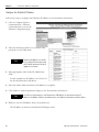
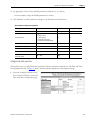
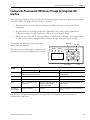
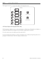
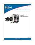
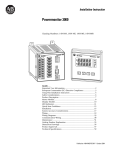
Energy Management Connected Components
Building Block - Capacitor Bank Controller
Application
Quick Start
Important User Information
Solid state equipment has operational characteristics differing from those of electromechanical equipment. Safety Guidelines
for the Application, Installation and Maintenance of Solid State Controls (publication SGI-1.1 available from your local Rockwell
Automation sales office or online at http://www.rockwellautomation.com/literature/) describes some important differences
between solid state equipment and hard-wired electromechanical devices. Because of this difference, and also because of the
wide variety of uses for solid state equipment, all persons responsible for applying this equipment must satisfy themselves that
each intended application of this equipment is acceptable.
In no event will Rockwell Automation, Inc. be responsible or liable for indirect or consequential damages resulting from the use
or application of this equipment.
The examples and diagrams in this manual are included solely for illustrative purposes. Because of the many variables and
requirements associated with any particular installation, Rockwell Automation, Inc. cannot assume responsibility or liability for
actual use based on the examples and diagrams.
No patent liability is assumed by Rockwell Automation, Inc. with respect to use of information, circuits, equipment, or software
described in this manual.
Reproduction of the contents of this manual, in whole or in part, without written permission of Rockwell Automation, Inc., is
prohibited.
Throughout this manual, when necessary, we use notes to make you aware of safety considerations.
WARNING
Identifies information about practices or circumstances that can cause an explosion in a hazardous environment,
which may lead to personal injury or death, property damage, or economic loss.
IMPORTANT
Identifies information that is critical for successful application and understanding of the product.
ATTENTION
Identifies information about practices or circumstances that can lead to personal injury or death, property damage,
or economic loss. Attentions help you identify a hazard, avoid a hazard, and recognize the consequence
SHOCK HAZARD
Labels may be on or inside the equipment, for example, a drive or motor, to alert people that dangerous voltage may
be present.
BURN HAZARD
Labels may be on or inside the equipment, for example, a drive or motor, to alert people that surfaces may reach
dangerous temperatures.
Rockwell Automation, Allen-Bradley, Powermonitor 1000, PanelView Component, RSLogix 500, RSEnergyMetrix, RSLinx Classic, RSPower, and TechConnect are either trademarks or registered trademarks of Rockwell
Automation, Inc.
Trademarks not belonging to Rockwell Automation are property of their respective companies.
Where to Start
Follow the path below to complete your connected components building block.
Connected Components
Building Blocks, publication
CC-QS001
Chapter 1 Powermonitor 1000 Device Configuration
Chapter 2 System Validation and Application Tips
3Publication CC-QS023A-EN-P - October 2010
3
Where to Start
Notes:
4
Publication CC-QS023A-EN-P - October 2010
Table of Contents
Preface
Introduction . . . . . . . . . . . . . . . . . . . . . . . . . . . . . . . . . . . . . . . . . . . . . . . 7
Conventions Used in This Manual . . . . . . . . . . . . . . . . . . . . . . . . . . . . . 8
Additional Resources . . . . . . . . . . . . . . . . . . . . . . . . . . . . . . . . . . . . . . . . 8
Chapter 1
Powermonitor 1000 Device
Configuration
Introduction . . . . . . . . . . . . . . . . . . . . . . . . . . . . . . . . . . . . . . . . . . . . . . . 9
Before You Begin. . . . . . . . . . . . . . . . . . . . . . . . . . . . . . . . . . . . . . . . . . . 9
What You Need . . . . . . . . . . . . . . . . . . . . . . . . . . . . . . . . . . . . . . . . . . . 10
Follow These Steps . . . . . . . . . . . . . . . . . . . . . . . . . . . . . . . . . . . . . . . . 10
Configure a Powermonitor 1000 Device . . . . . . . . . . . . . . . . . . . . . . . 11
Configure the Powermonitor 1000 Device Through the
Integrated LCD Interface . . . . . . . . . . . . . . . . . . . . . . . . . . . . . . . . . . . 17
Additional Resources . . . . . . . . . . . . . . . . . . . . . . . . . . . . . . . . . . . . . . . 22
Chapter 2
System Validation and Application Introduction . . . . . . . . . . . . . . . . . . . . . . . . . . . . . . . . . . . . . . . . . . . . . . 23
Before You Begin. . . . . . . . . . . . . . . . . . . . . . . . . . . . . . . . . . . . . . . . . . 23
Tips
What You Need . . . . . . . . . . . . . . . . . . . . . . . . . . . . . . . . . . . . . . . . . . . 24
Follow These Steps . . . . . . . . . . . . . . . . . . . . . . . . . . . . . . . . . . . . . . . . 25
PanelView Component Configuration . . . . . . . . . . . . . . . . . . . . . . . . . 26
Additional Resources . . . . . . . . . . . . . . . . . . . . . . . . . . . . . . . . . . . . . . . 35
Appendix A
Frequently Asked Questions
5Publication CC-QS023A-EN-P - October 2010
Introduction . . . . . . . . . . . . . . . . . . . . . . . . . . . . . . . . . . . . . . . . . . . . . . 37
5
Table of Contents
Notes:
6
Publication CC-QS023A-EN-P - October 2010
Preface
Introduction
This quick start is designed to provide a way to implement and use a
connected component for energy management. To assist in the design and
installation of your system, application files and other information are
provided on the Connected Components Building Blocks Overview CD,
publication CC-QR001. The CD provides bills of materials (BOM), CAD
drawings for panel layout and wiring, control programs, Human Machine
Interface (HMI) screens, and more. With these tools and the built-in bestpractices design, the system designer is free to focus on the design of their
machine control and not on design overhead tasks. The beginning of each
chapter contains the following information. Read these sections carefully
before beginning work in each chapter:
• Before You Begin - This section lists the steps that must be completed
and decisions that must be made before starting that chapter. The
chapters in this quick start do not have to be completed in the order in
which they appear, but this section defines the minimum amount of
preparation required before completing the current chapter.
• What You Need - This section lists the tools and equipment that are
required to complete the steps in the current chapter. This includes, but
is not limited to, hardware and software.
• Follow These Steps - This illustrates the steps in the current chapter
and identifies the steps required to complete the examples.
Use this Energy Management Connected Components Building Block Quick
Start in conjunction with the Connected Components Building Blocks Quick
Start, publication CC-QS001.
Refer to Additional Resources on page 8 for a listing of quick starts.
ATTENTION
Rockwell Automation has no liability on Capacitor Bank controller application. Rockwell
Automation is not the supplier of the Capacitor Bank. This guide is written for a qualified engineer
that understands power quality and power correction application.
Publication CC-QS023A-EN-P - October 2010
7
Preface
Conventions Used in This
Manual
This manual uses these conventions.
Convention
Meaning
Example
Check or uncheck
To activate or deactivate a checkbox.
Check Disable Keying.
Click
Click the left mouse button once while the cursor is positioned
on object or selection.
Click Browse.
Select
Use the mouse to highlight a specific option.
Select the New Module folder.
Enter
What you type.
Enter your choice.
>
Use this symbol to indicate the sub-menu name.
Choose File > Menu > Options.
Additional Resources
Resource
Description
Connected Components Building Blocks Quick Start, Provides information on how to select products and gain access to panel and wiring
publication CC-QS001
information.
8
Connected Component Building Blocks Overview
CD, publication CC-QR001
Provides files for the Connected Component Building Blocks.
http://www.ab.com
Provides access to the Allen-Bradley website.
Powermonitor 1000 User Manual,
publication 1408-UM001
Provides information for using the Powermonitor 1000 device.
Powermonitor 1000 Installation Instructions,
publication 1408-IN001
Provides information for installing the Powermonitor 1000 device.
Capacitor Bank Controller User Manual, publication
1413-UM001
Provides information for using the Capacitor Bank Controller.
PanelView Component Operator Terminals User
Manual, publication 2711C-UM001
Provides information on using the PanelView Component HMI terminals.
PanelView Component Installation Instructions,
publication 2711C-IN001
Provides installation information for the PanelView Component terminal.
MicroLogix 1400 Programmable Controllers
Installation Instructions, publication 1766-IN001
Provides installation information for the MicroLogix 1400 programmable controller.
MicroLogix 1400 Programmable Controllers User
Manual, publication 1766-UM001
Provides information on using the MicroLogix 1400 programmable controller
RSEnergyMetrix Getting Results Guide, publication
ENEMTX-GR001
Provides information about using RSEnergyMetrix software.
Current Transformer Selection Matrix, publication
1411-SG001
Provides a selection matrix for choosing your current transformer.
http://www.rockwellautomation.com/
knowledgebase
Provides access to self-service support.
http://www.rockwellautomation.com/components/
connected
Provides access to the Connected Components website.
Publication CC-QS023A-EN-P - October 2010
Chapter
1
Powermonitor 1000 Device Configuration
Introduction
In this chapter, you will learn to configure a Powermonitor 1000 device.
For other configuration parameters such as, Wiring Mode WYE, Delta, Potential/Current Transformer
ratios, Demand periods, and advanced configuration, you need to consult these Powermonitor 1000
publications:
•
Bulletin 1408 Powermonitor 1000 User Manual, publication 1408-UM001
•
Powermonitor 1000 Unit Installation Instructions, publication 1408-IN001
Before You Begin
•
Review the Energy Management Connected Component Building Blocks common folder to understand
important background information regarding your Powermonitor device and software package.
•
Select hardware and wire your Powermonitor 1000 device. Refer to the Powermonitor 1000 Unit
Installation Instructions, publication 1408-IN001, for reference.
Publication CC-QS023A-EN-P - October 2010
9
Chapter 1
Powermonitor 1000 Device Configuration
What You Need
•
Powermonitor 1000 unit
•
Current transformers and potential transformers (if required, refer to the Powermonitor 1000 User
Manual, publication 1408-UM001)
•
Product manuals
– Bulletin 1408 Powermonitor 1000 User Manual, publication 1408-UM001
– Powermonitor 1000 Unit Installation Instructions, publication 1408-IN001
– PanelView Component User Manual, publication 2711C-UM001
Follow These Steps
Follow these paths to configure the Powermonitor device and PanelView Component device in your energy
system management.
Configure a Powermonitor 1000 Device
Start
Configure
Powermonitor 1000
Device Parameters
through a Web
Browser, page 11
Configure the
EtherNet/IP Address,
page 12
Configure Analog
Inputs, page 13
Configure Advanced
Device Parameters,
page 14
Configure the Date
and Time, page 15
Configure the
Powermonitor 1000
Device Through the
Integrated LCD
Interface, page 17
10
Publication CC-QS023A-EN-P - October 2010
Powermonitor 1000 Device Configuration
Chapter 1
Configure a Powermonitor 1000 Device
This section shows you how to configure parameters of a Powermonitor 1000 device by using the internal
LCD display and configuration web page. Certain settings are needed for the Powermonitor 1000 device to
meter, communicate, and work with RSEnergyMetrix software. You will set the network configuration,
Voltage mode, PT and CT ratios, demand values, and the date and time. Your application may require
additional configuration.
Network configuration is provided for the Powermonitor 1000 device on the Ethernet network. For other
communication options, refer to the Powermonitor 1000 Unit Installation Instructions, publication
1408-IN001.
TIP
Configure Powermonitor 1000 Device Parameters through a Web Browser
Follow these steps to configure Powermonitor 1000 device parameters.
1. Launch the Internet browser on your computer.
2. In the Address field, type the IP address of your Powermonitor 1000 device.
The default IP address is 192.168.254.xxx, where xxx is the unit’s ID. The default address simplifies the
task of making the initial connection to the unit from a personal computer.
http://192.168.254.23
TIP
You can check the IP address of the Powermonitor 1000 device from its display or by
using RSLinx Classic software and configuring an EtherNet/IP driver.
Publication CC-QS023A-EN-P - October 2010
11
Chapter 1
Powermonitor 1000 Device Configuration
Configure the EtherNet/IP Address
Follow these steps to configure the EtherNet/IP address of a Powermonitor 1000 device.
1. Choose Configure Options>
Communication > Ethernet
Communications to access the
Ethernet Configuration page.
2. Enter the default password of 0 or another valid
password to access Edit mode.
TIP
The password appears as asterisks
(*). If you don’t know the password,
call Rockwell Automation technical
support for assistance.
1
3. Enter appropriate values in the IP Address Byte
fields.
For this example, the IP address is 10.10.10.1 for
the first Powermonitor 1000 device.
4. Enter the Subnet Mask and Gateway IP addresses as required.
5. Click Submit to send the parameter changes to the Powermonitor 1000 device.
TIP
You will lose communication to the Powermonitor 1000 device. You must enter the new IP
address in the Address field of your web browser to re-establish communication with the device.
6. Browse to the new IP address from your web browser.
The IP address is shown on the default LCD display screen.
12
Publication CC-QS023A-EN-P - October 2010
Powermonitor 1000 Device Configuration
Chapter 1
Configure Analog Inputs
Follow these steps to configure the Voltage mode, PT ratios, and CT ratios for the Powermonitor 1000
device. The Analog Input Set-up Parameters table on page 14 shows the analog input parameters and
example settings.
1. From the Configure Options menu, choose
Analog Input to display the Analog Input
Configuration page.
600
2. Enter the default password of 0 or another
valid password to access Edit mode.
TIP
The password appears as asterisks
(*). If you don’t know the
password, call Rockwell
Automation technical support for
assistance.
3. Enter the value of the Voltage Mode you are
using.
4. Set elements 2, 3, and 4 to configure the PT
and CT parameters.
5. Click Submit to send the parameter changes to the Powermonitor 1000 device.
Publication CC-QS023A-EN-P - October 2010
13
Chapter 1
Powermonitor 1000 Device Configuration
Analog Input Set-up Parameters
Parameter
Range
Default
Example Settings
Password
0…9999
0
0
Voltage Mode
0…6
0 = Direct Delta
1 = Open Delta
2 = Wye
3 = Single Phase
4 = Demo, simulated results
5 = 1PT1CT-LL
6 = 1PT1CT-LN
2
2
PT Primary
1.0…50,000
480
480
PT Secondary
5.00…50,000
480
480
CT Primary
5.00…50,000
5
600
System PF Setting
0 = Lead (-97…89)
1 = High (-85…98)
2 = Low (-52…-95)
2 = Low
2
Configure Advanced Device Parameters
Follow these steps to configure advanced demand parameters for the Powermonitor 1000 device. These
settings include demand source, demand period length, and the number of demand periods to average for the
demand calculation. The Advanced Device Configuration Parameters table on page 15 shows the demand
parameters and example settings.
1. From the Configure
Options menu, choose
Advanced to access the
Advanced Configuration
page.
2. Enter the default password of 0 or another valid
password to access Edit mode.
TIP
The password appears as asterisks
(*). If you don’t know the password, call
Rockwell Automation technical support
for assistance.
14
Publication CC-QS023A-EN-P - October 2010
Powermonitor 1000 Device Configuration
Chapter 1
3. Set appropriate values for the demand parameters (elements 14, 15, and 16).
For this example, accept the default parameters as shown.
4. Click Submit to send the parameter changes to the Powermonitor 1000 device.
Advanced Device Configuration Parameters
Parameter
Range
Default
Example Settings
Password
0…9999
0
0
Demand Source
0…3
0 = Internal Timer
1 = Status Input 2
2 = Controller Command
3 = Ethernet Demand Broadcast
0
0
Demand Period Length
0…99 min
15 min
15
Number of Demand Periods
1…15
1
1
Forced Demand Sync Delay
0…90 s
10
Demand Broadcast Master Select
0…1
0
Broadcast Port Number
(Ethernet Setup)
300…400
300
Configure the Date and Time
Follow these steps to configure the date and time for the Powermonitor 1000 device. The Date and Time
Set-up Parameters table on page 16 shows the date and time parameters, and example settings.
1. From the Configure Options menu,
choose Date and Time to access the
Date and Time Configuration page.
Publication CC-QS023A-EN-P - October 2010
15
Chapter 1
Powermonitor 1000 Device Configuration
2. Enter the default password of 0 or another valid
password to access Edit mode.
The password appears as asterisks (*).
If you don’t know the password, call
Rockwell Automation technical support
for assistance.
TIP
3. Configure the date and time parameters
accordingly.
4. Click Submit to send the parameter changes to the
Powermonitor 1000 device.
Date and Time Set-up Parameters
Parameter
Range
Default
Example Settings
Password
0…9999
0
0
Date: Year
2001…2100
2005
Date: Month
1…12
1
Date: Day
1…31
0
Time: Hour
0…23
0
Time: Minute
0…59
0
Time: Seconds
0…59
0
Time: Hundredths 0…59
0
TIP
16
For a full Powermonitor 1000 LCD screen display and configuration map, see pages 30…32 of the
Powermonitor 1000 Installation Instructions, publication 1408-IN001.
Publication CC-QS023A-EN-P - October 2010
Powermonitor 1000 Device Configuration
Chapter 1
Configure the Powermonitor 1000 Device Through the Integrated LCD
Interface
The Powermonitor 1000 device has an onboard LCD for viewing and configuration. Buttons are provided to
control the display. The display has three modes of operation:
•
Display mode lets you select and view parameters including metering, event log, and self-test
information.
•
Program mode lets you change configuration parameters, with security against unauthorized
configuration changes. Each Powermonitor 1000 device is password protected.
•
Edit mode lets you modify the selected parameters. In Edit mode, a highlight cursor appears under
the value of the parameter being modified, starting at the right-hand (least significant) digit.
The diagram and table shows the LCD interface
buttons and their functions.
The buttons function differently in each mode. The
power monitor enters into Display mode by default.
Up Arrow
RS-485
RX
TX
STATUS
Escape
Powermonitor 1000
Mod Net
Down Arrow
Button
Enter
Mode
Display
Program
Edit
Escape
Returns to parent menu
At top menu, selects default screen
Cancels changes to the parameter and returns
to Program mode
Up arrow
Steps back to the previous parameter or menu item
Increments the value of the highlighted digit
Down arrow
Steps forward to the next parameter or menu item
Decrements the value of the highlighted digit
Enter
Steps into a sub-menu or sets
default screen
Steps into a sub-menu, selects the
parameter to be modified or
changes to Edit mode
Saves the parameter change and returns to
Program mode
Up and down
arrows together
Refreshes the display
No effect
Moves the highlight cursor one character to
the left
User choices for display and configuration are organized in a hierarchical menu system within the
Powermonitor 1000 device.
Publication CC-QS023A-EN-P - October 2010
17
Chapter 1
Powermonitor 1000 Device Configuration
This diagram shows how to navigate in the display and configuration menu.
Chart Key
Default
Screen
Level 1
Next Item
(within current level)
Level 2
Level 3
Level 4
Previous Item
(within current level)
Select
LCD Screen Display and Configuration Menu Map
The Powermonitor 1000 device lets you select and navigate to a default screen. The default screen displays at
startup and is displayed after the display has been dormant for approximately 30 minutes.
To set the current screen as the default, press Enter and click Yes.
If you’re in another menu and want to get back to the default screen, continue pressing Escape until you are
prompted ‘To Default Screen?’ Click Yes to display the default screen.
18
Publication CC-QS023A-EN-P - October 2010
Powermonitor 1000 Device Configuration
Chapter 1
Main Menu, Page 1
Default
Screen?
Level 1
Display
Program
Password?
Level 2
Display
Config
Setup
Display
Metering
Level 3
Metering Volts
Amps
Frequency(1)
Metering
Power(1)(2)
Metering
Energy(1)
PF 1
PF 2
PF 3
PF Total
KW 1
KW 2
KW 3
KW Total
KVAR 1
KVAR 2
KVAR 3
KVAR Total
KVA 1
KVA 2
KVA 3
KVA Total
Status 1 Cnt
Status 2 Cnt
kWH Fwd
kWH Rev
kWH
kVARH Fwd
kVARH Rev
kVARH
kVAH
kW Demand
kVAR Demand
kVA Demand
PF Demand
kW Proj Demand
kVAR Proj Demand
kVA Proj Demand
See Setup
Submenu
Level 4
I1
I2
I3
I Average
V LN1
V LN2
V LN3
V L12
V L23
V L31
V LN Avg
V LL Avg
Frequency
Unbalance V
Unbalance I
(1) The Catalog Number and Voltage mode
determine which parameters are displayed.
(2)
Individual phase parameters are not
displayed in Delta modes.
Main Menu, Page 2
Level 2
Display Wiring
Diagnostics
Display Run
Status
Display I/O
Status
Program
Commands
Program
Setup
Wiring Status
Volts Input Missing
Volts Input Inverted
Amps Input Missing
Amps Input Inverted
Voltage Rotation
Amps ROtation
VOlts Ph1 Angle
Volts Ph1 Magnitude
Volts Ph2 Angle
Volts Ph2 Magnitude
Volts Ph3 Angle
Volts Ph3 Magnitude
Amps Ph1 Angle
Amps Ph1 Magnitude
Amps Ph2 Angle
Amps Ph2 Magnitude
Amps Ph3 Angle
Amps Ph3 Magnitude
Series Number
Catalog Number
Comm Type
WIN Number
Application FRN
Boot Code FRN
Default Device ID
Accuracy Class
Overall Status
Flash Memory
SRAM Memory
NVRAM Memory
SPI Interface
Real Time Clock
Watchdog Timer
Metering Status
LCD Interface
Serial Interface
Ethernet Interface
Input Over Range
Phase Loss Detection
Terminals Locked
Date
Time
KYZ Status
S1 Status
S1 Status Count
S2 Status
S2 Status Count
Output Word
Clear kWh Registers
Clear kVARh Registers
Clear kVAh Registers
Clear Energy All
Registers
Clear Status 1 Count
Clear Status 2 Count
Force KYZ On
Force KYZ Off
Remove KYZ Force
Restore Defaults
Test Wiring Connections
Reset System
Clear Min/Max Log
Perform Wiring Diagram
Store Load Factor
Record
Clear Load Factor Log
Store TOU Record
Clear TOU Log
Troubleshooting Password
See Setup
Submenu
Level 3
Publication CC-QS023A-EN-P - October 2010
19
Chapter 1
Powermonitor 1000 Device Configuration
Setup Submenu
Configuration Mode
Level 2 Program Mode, Level 3 Display Mode
Analog Input
Advanced
RS485
Ethernet
New Password
Date
Time
Meter Averaging
DST Enable
DST Start
Month, Wk, Day
DST Start Hour
DST End
Month, Wk, Day
DST End Hour
KYZ Output Select
KYZ Output Scale
KYZ Pulse Duration
Status 1 Input Scale
Status 2 Input Scale
Demand Source
Demand Length
Demand Periods
Demand Sync Delay
Unit Error Action
Error Log Full Action
LCD Display Contrast
Protocol Setting
Serial Delay mS
Baud Rate
Serial Address
Serial Data Format
Inter Character
Timeout
Max Node Address
IP Address Byte a
IP Address Byte b
IP Address Byte c
IP Address Byte d
Subnet Mask Byte a
Subnet Mask Byte b
Subnet Mask Byte c
Subnet Mask Byte d
Gateway Byte a
Gateway Byte b
Gateway Byte c
Gateway Byte d
SNTP Mode Select
SNTP Update Rate
SNTP Time Zone
Time Server Byte a
Time Server Byte b
Time Server Byte c
Time Server Byte d
Broadcast Mode
Broadcast Port
Level 3, 4
Voltage Mode
PT Primary
PT Secondary
CT Primary
System PF Setting
Edit a Parameter
Follow these guidelines to edit a parameter:
•
Press <up> or <down> to change the highlighted digit.
•
Press <up> and <down> together to move the highlight cursor one place to the left, and press
<up> or <down> to set the selected digit’s value.
Continue in the same way until the correct value is entered, then press <enter> when done.
Setup Example
This example steps through setting the unit date to demonstrate use of the display and buttons to navigate
through the setup menu and make changes to parameters.
1. Navigate to the initial screen.
The screen shown is the top level
screen. If it is not present, press
<escape> until it appears.
RS-485
RX
TX
STATUS
Powermonitor 1000
Mod Net
Power And
Energy Management
Solutions
If you press <escape> once too often,
the ‘To Default Screen?’ message
appears. Press <escape> once more if
this occurs.
20
Publication CC-QS023A-EN-P - October 2010
Powermonitor 1000 Device Configuration
Chapter 1
2. Press <enter> and this screen appears.
RS-485
RX
STATUS
TX
Powermonitor 1000
Mod Net
Display
3. Press <up> or <down> once,
Program appears in the display, then
Press <enter>.
RS-485
RX
4. Press <enter> if the password has not
been changed from the default (0000).
TX
Powermonitor 1000
Mod Net
Password
o
If the password has been changed,
then enter the correct password.
When the correct password is
entered, Program Setup appears in the
display. The Powermonitor 1000
device is now in Program mode.
STATUS
0000
RS-485
RX
STATUS
TX
Powermonitor 1000
Mod Net
Program
If an incorrect password is entered,
Invalid Password appears. Press any
button to try again.
Setup
5. Press <enter>.
Analog Input appears in the display.
Press <down>.
RS-485
RX
TX
STATUS
Powermonitor 1000
Mod Net
Advanced
Setup
Publication CC-QS023A-EN-P - October 2010
21
Chapter 1
Powermonitor 1000 Device Configuration
6. With Advanced Setup displayed,
press <enter>, then press <down>
until Set Date Year appears.
RS-485
RX
TX
STATUS
Powermonitor 1000
Mod Net
Set Date
Year
7. Press <enter> to change the value of
the year.
The Powermonitor 1000 device is
now in Edit mode, indicated by the
presence of the highlight cursor.
Change the year value and press
<enter> to save it or <escape> to
discard changes.
2008
RS-485
RX
TX
STATUS
Powermonitor 1000
Mod Net
Set Date
Year
20058
See Edit a Parameter, page 20 if you
need help with this.
8. Select the next item in the configuration menu by pressing <down>.
Set the month in the same way.
9. Continue setting the remaining parameters in the same way.
a.
b.
c.
d.
e.
f.
g.
h.
i.
Navigate to the top menu display.
Press <enter> then <down> then <enter> to access the password screen.
Enter the correct password to access Program mode.
Navigate to the desired menu using <enter>, <up> and <down>.
Press <enter> selects a parameter for editing.
Press <up> or <down> increments or decrements the value of the highlighted digit.
Press <up> and <down> together move the highlight cursor.
Press <enter> saves your changes; <escape> discards them.
Press <escape> several times to the top menu to access Display mode.
Additional Resources
Refer to page 8 for a listing of product and information resources.
22
Publication CC-QS023A-EN-P - October 2010
Chapter
2
System Validation and Application Tips
Introduction
The Capacitor Bank controller is intended for standard, fixed-function Capacitor Banks. The controller
consists of standard, off-the-shelf, Allen-Bradley hardware with the application ladder code necessary to
perform power factor correction. The controller is designed to provide the same base functionality as a fixed
function Capacitor Bank controller. This application provides the control scheme for Capacitor Banks
through a MicroLogix 1400 controller with a PanelView Component C600 HMI terminal interface.
Rockwell Automation is not the supplier of the Capacitor bank.
In this chapter, you will configure the communication for your application. You will learn how to do the
following:
• Connect and configure a MicroLogix 1400 controller to a PanelView Component terminal for
Capacitor Bank controller application.
• Configure RSEnergyMetrix software to log your Powermonitor 1000 device data and the
MicroLogix 1400 controller data.
Before You Begin
•
•
•
•
Review the MicroLogix 1400 User Manual, publication 1766-UM001
Review the PanelView Component User Manual, publication 2711C-UM001
Review the Capacitor Bank Controller User Manual, publication 1413-UM001
Optional - Install RSEnergyMetrix software (Review the RSEnergyMetrix Getting Results Guide,
publication ENEMTX-GR001)
• Optional - Install RSLogix 500 software version 8.1 or later (Review the RSLogix 500 Getting
Results Guide, publication LG500-GR002)
• Configure Powermonitor 1000 devices, refer to Chapter 1
• Configure the PanelView Component terminal
23Publication CC-QS023A-EN-P - October 2010
23
Chapter 2
System Validation and Application Tips
What You Need
• MicroLogix 1400 controller hardware and RSLogix 500 software, version 8.1 or later, for
downloading the CAP Bank Controller program to the controller connected over the same Ethernet
network as the PanelView Component terminal and the Powermonitor 1000 device
• Powermonitor 1000 device
• PanelView Component 600 Touch terminal
• USB flash drive (for loading the PanelView application)
• Personal computer with Internet access for launching and using RSEnergyMetrix software
• RSEnergyMetrix CD, catalog number 9307-ENEMTXCD
• RSEnergyMetrix online help and Getting Results Guide, publication ENEMTX-GR001
24
Publication CC-QS023A-EN-P - October 2010
System Validation and Application Tips
Chapter 2
Follow These Steps
Follow these steps to verify that communication is occurring between your devices.
Start
Loading Capacitor Bank
Application to MicroLogix
Controller (PLC) and to
PanelView Component
(HMI) Terminal
page 26
PanelView Component C600
Screens Quick Navigation
for Capacitor Bank
Controller Energy Solution
page 28
Capacitor Bank
Commissioning Checklist
page 33
Customize Your
PanelView Component
Application
page 34
Publication CC-QS023A-EN-P - October 2010
25
Chapter 2
System Validation and Application Tips
PanelView Component Configuration
Loading Capacitor Bank Application to MicroLogix Controller (PLC) and to PanelView
Component (HMI) Terminal
Follow these steps to download the Capacitor Bank controller preconfigured with the PanelView Component
project to the 6-inch touch terminal.
1. Power up the PanelView Component 6-inch touch terminal, the MicroLogix1400 controller, and the
Powermointor 1000 unit.
TIP
The PanelView Component terminal is powered with a 24V DC supply. The PanelView Component HMI
power wiring is illustrated in the Connected Building Block CD.
The MicroLogix 1400 controller, catalog number 1766-L32BWA, and Powermonitor 1000 unit are powered
with 110/240V AC.
IMPORTANT
It is very critical that the Powermonitor 1000 unit is wired correctly with PT/CT arrangements. Incorrectly
wiring the CT's polarity and/or misalignment with respective voltage channel will result in wrong metering
data information that will cause unexpected control of Capacitor Banks.
2. Verify that all Powermonitor 1000 units and the MicroLogix 1400 controller are online and reside on
same network as the PanelView C600 terminal.
Powermonitor 1000 Unit
(up to four units)
RS-485
EtherNet/IP
RS-485
RX
+
ACT
-
STATUS
TX
Powermonitor 1000
Mod Net
SHLD
LNK
MicroLogix 1400 Controller
PanelView Component C600 Terminal
ESC
OK
Customer Switch/Network
From Plant (customer) Network
RSEnergyMetrix, or Other Network
TIP
26
Powermonitor 1000 firmware revision 3.x is supported. You can update the Powermonitor 1000 unit by
using ControlFLASH software.The latest upgrade can be obtained from firmware update site
http://www.ab.com/PEMS/downloads.html.
Publication CC-QS023A-EN-P - October 2010
System Validation and Application Tips
Chapter 2
The PanelView C600 application is preconfigured for the following:
• MicroLogix 1400 IP address = 192.168.254.100
• PanelView C600 IP address = 192.168.254.105
The MicroLogix 1400 controller communicates with the Powermonitor 1000 unit (default
Powermonitor unit IP address 192.168.254.63). There is no direct communication data exchange
between the PanelView Component terminal and the Powermonitor 1000 unit.
Assign an IP address for the personal computer workstation for downloading the PLC program and/or
transferring the HMI project to the HMI.
IMPORTANT
RSLogix 500 software, version 8.1 or later, RSLinx software, version 2.56 or later, and the
Internet Explorer web browser, version 7.0 or later, should be installed with IP address
192.168.254.110.
3. Copy the PanelView Component application ‘1413_CAP_V3.cha’ from the Connected Component
Building Block CD to the root of USB flash drive.
TIP
PanelView Component terminal firmware revision 1.3x is supported. If your terminal is at an earlier
revision, a firmware upgrade is included in this Building Block content.
4. Copy the MicroLogix application ‘1413_CAP_v3.RSS’ to the workstation and download it to the
MircoLogix 1400 controller.
5. Plug the USB drive into the PanelView Component terminal.
The USB connection is on the back side of PanelView C600 terminal.
TIP
This application was developed for a PanelView Component 6-inch touch screen unit only. To transfer
the application to the PanelView Component terminal, see the PanelView Component HMI Terminals
Quick Start, publication 2711C-QS001.
Go to Config > File Manager > Source (USB) > Select 1413_CAP_V3.cha file, and copy it to the
internal memory of the PanelView Component terminal.
6. Configure the Screensaver/Start-up application as desired from the PanelView Component terminal
settings, then run the 1413_CAP_v3 Capacitor Bank application file.
7. Verify that the PanelView Component terminal is displaying Capacitor Bank controller data.
TIP
An asterisk '*' indicates the following:
• A communication error
• The value has more significant digits than HMI applications
Publication CC-QS023A-EN-P - October 2010
27
Chapter 2
System Validation and Application Tips
PanelView Component firmware revision 1.3, and Powermonitor firmware revision 3.1 is included
on the building block CD.
TIP
The PanelView Component C600 terminal provides easy navigation in configuring and/or viewing the
Capacitor Bank application through its touch screen.
This flowchart illustrates a high-level navigation through different screens in the Capacitor Bank of the
PanelView Component terminal.
Overview
Summary
Navigation/Menu
Step Status
Extended
Status
Step
Control
PF Summary
PM1K #1 Data
PM1K #2 Data
(optional)
PM1K #3 Data
(optional)
Alarm Summary
Configuration
Extended
Configuration
Extended
Configuration 2
PM1K #4 Data
(optional)
TIP
28
Only solid fields are configurable; that is, the values in solid fields can be changed.
Publication CC-QS023A-EN-P - October 2010
System Validation and Application Tips
These images show the navigation through the
PanelView Component terminal.
Chapter 2
Home Screen
Clicking each button provides navigation to
the configuration and metering screens.
This screen shows current realtime Power (kW,
kVAR, and powerfactor) and displays the
status of which Capacitor Bank steps are
currently On or OFF.
TIP
Each screen, except the menu screen, has six buttons as a footer that provides navigation. For example,
on the overview screen ‘PM#1 Data’ will navigate to the Powermonitor data screen.
Use the Prev navigation link to all screens (except Menu/Overview) to go back.
Navigation/Menu Screen
This screen provides navigation to the different
screens.
Publication CC-QS023A-EN-P - October 2010
29
Chapter 2
System Validation and Application Tips
In this screen you can configure:
Configuration
• the number of steps. The default
value is 10; that will show all 10 steps.
Num Step is between 1 and 10.
• Number of Powermonitors from
1…4. Default is 1. At least one
Powermonitor unit must be
configured.
• Steps in kVAR. This is the size of
each capacitor. Step 1 is wired to
Output 1 (Capacitor Bank step 1
contact) of the MicroLogix controller
and step 10 is wired to output 10
(Capacitor Bank step 10 contact).
IMPORTANT
Stages and/or sizes of the Capacitor Bank typically require a Power Quality study. The Capacitor
Bank modes are Manual, FILO, Balanced, and Best Fit.
IMPORTANT
For Discharge Time, check with the Capacitor Bank vendor for the appropriate value. One
discharge Capacitor Bank value applies to all capacitor steps.
These guidelines apply in the Configuration
screen:
Configuration
• Nominal Volts is a number between
0 and 9999 using the scale
1/10/100/1000. Therefore, a voltage
of 13,400V would be entered as
1340.
• Volt Range % is used for voltage
high/low alarms.
• Timer preset is for high and low
values for the high/low voltage
alarms.
• PF timer is used to generate alarm if
Powerfactor is not achieve in that
time.
TIP
30
All timers are in seconds.
Publication CC-QS023A-EN-P - October 2010
System Validation and Application Tips
These guidelines apply in the Configuration
screen:
Chapter 2
Configuration
• The Samples to Avg number is
between 5 and 10.
• The kVAR tolerance % of each
capacitor to trigger alarming.
• Input mode is disabled by default. If
you are using fault relays for
respective steps, we recommend that
you use Input mode. Reset inputs
will clear controller alarms.
TIP
The leading kVAR limit allowed for the system, before the controller acts to correct lead, typically is 33%
of smallest capacitor step. The lagging kVAR limit allowed for the system, before the controller acts to
correct lag, typically is 66% of largest capacitor step.
Step Control
This screen shows the step control of the
Capacitor Bank controller. Step Control
screens let you place a step in Auto (A) or
Manual (M) mode.
When using the Balanced, Best Fit, or FILO
operating mode, make sure all the steps are in
Auto mode. Just pressing the step will toggle
the step in Auto (A) or Manual (M) mode.
The first row (from the left) is to configure
the step; the second row is the status of step
(A or M).
The third row is Manual command. You can
press the respective step and if it is in Manual mode you can turn that step On or Off.
The second-last row indicates On/Off status of each step. The last row shows discharging status. If a
Capacitor Bank is discharging, it will show a flashing ‘D’.
Publication CC-QS023A-EN-P - October 2010
31
Chapter 2
System Validation and Application Tips
Operating Mode Screen
This screen shows the Operating mode. Verify
your steps are configured properly before
making Operating mode selections:
• Manual (mode = 0) – This mode
disables all automatic operating
modes. Manual mode is the default
configuration. All capacitor steps have
a default configuration of auto.
• FILO (mode = 1) – This mode of
operation switches the capacitor steps
on and off in first-in, last-out (FILO)
order. That is, the first step on is the
last step turned off. This is most useful
when all the capacitor steps are of
similar size.
Balanced (mode = 2) – This mode counts the number of opening operations on each capacitor step
and switch-capacitor steps to balance the number of opening operations equally across all of the
employed capacitor steps. This mode is also most useful when all of the steps are of similar size.
• Best Fit (mode = 3) – This mode selects capacitor steps to be switched on and off to most closely
achieve the target power factor and kVAR needs of the system. When the system’s kVAR needs to
increase, the available step or steps with the closest (aggregated) kVAR rating is added. On
decreasing kVAR demand, steps are switched off in similar fashion.
32
Publication CC-QS023A-EN-P - October 2010
System Validation and Application Tips
Chapter 2
Administration Screen
The Admin screen provides the IP address of
the Powermonitor units used in the Capacitor
Bank controller.
The default IP address for the Powermointor
1000 unit in this application is
192.168.254.63. After changing the IP
address, you must press Config IP for the
controller to change the IP address in the
explicit messaging.
ATTENTION
ATTENTION
Changing the IP address causes all of the capacitors to turn off and that can cause a power disturbance.
Rockwell Automation has no liability on Capacitor Bank controller applications. Rockwell Automation is
not the supplier of the Capacitor Bank. This document is written for a qualified engineer that understands
power quality and power correction application.
Capacitor Bank Commissioning Checklist
Follow this checklist prior to using the Capacitor Bank:
• Wear proper personal protective equipment (PPE).
• Complete a Power Quality study to understand the power profile to staging the right step sizes of the
Capacitor Bank.
• Check that the Powermonitor unit is wired correctly.
• Check that the Overview screen shows valid Power data (kW, kVar, and Powerfactor). If no data is
displayed, go to the Admin screen and verify the IP address of the Powermonitor unit.
Publication CC-QS023A-EN-P - October 2010
33
Chapter 2
System Validation and Application Tips
As a minimum, the following configurations are required.
• Configuration is the number of steps configured with Discharge time, lead and/or lag settings.
• Configuration 1 and 2 are Nominal voltage, Voltage high/low limits, Powerfactor timers, samples to
average, and Input modes.
• Step Control configures all the steps in the appropriate mode.
• Operating mode is one of the three Automatic modes, FILO, Balanced, or Best Fit.
Customize Your PanelView Component Application
The text (units and meter names) and IP address of the Capacitor Bank controller can be configured through
the design environment.
TIP
For complete customization processes, see the PanelView Component HMI
Terminals Quick Start, publication CC-QS001.
Follow these steps to change the IP address of a Capacitor Bank controller in your PanelView Component
application.
1. Connect to the PanelView Component terminal through a web browser.
Use Mozilla FireFox, version 2.x or later, or Internet Explorer, version 7.0 or later, web browsers.
2. Type the IP address of your PanelView Component terminal.
3. On the home page, select the Capacitor Bank application and click Edit.
IMPORTANT
Make sure the pop ups are not blocked, as it will launch a new window.
4. Click the
Communication tab and
change the IP address as
needed.
The MicroLogix 1400
controller is configured
with 192.168.254.100 in
the 1413-CAP_v3.RSS.
34
Publication CC-QS023A-EN-P - October 2010
System Validation and Application Tips
Chapter 2
Additional Resources
Refer to page 8 for a listing of product and information resources.
Publication CC-QS023A-EN-P - October 2010
35
Chapter 2
System Validation and Application Tips
Notes:
36
Publication CC-QS023A-EN-P - October 2010
Appendix
A
Frequently Asked Questions
Introduction
This appendix provides some frequently asked questions regarding Capacitor Bank application and provides
some simple system troubleshooting.
1. When I click the Navigation links in the PanelView Component HMI, why doesn’t it bring up the
correct display?
A: Calibrate the touch screen on your PanelView Component HMI. Detailed instructions to recalibrate the touch screen can be found in the PanelView Component HMI User Manual,
publication 2711C-UM001. (Refer to Additional Resources on page 8.)
2. What does ‘Data Access Error for Alias…’ mean? (My terminal does not refresh and the data fields are
filled with ‘*’.)
A: Check the communication media (Ethernet Cat-5 cable). Verify proper wiring and communication
protocol settings on your PanelView Component HMI, MicroLogix controller, and Powermonitor
1000 device (IP addresses, default gateway, subnet mask).
3. I see some of the data for the metering parameters, but it shows ‘*’ on the least significant digit. What is
causing that?
A: The metering parameter in the PanelView Component application is programmed with a fixed
number of digits. Your data value is outside of the fixed digits. You need to customize the
PanelView Component application for your specific situation.
4. When I change screens in my PanelView Component application, I see asterisks in some of the data
boxes for a few seconds, but then the values become numbers. Why is this happening?
A: The default application is set for a 500 ms update rate for all tags. You can change the configuration
to 50 ms in the design environment to improve performance.
5. 5 How do i configure the lead and lag settings?
A: The leading kVAR limit allowed for the system, before the controller acts to correct lead, typically is
33% of smallest capacitor step. The lagging kVAR limit allowed for the system, before the
controller acts to correct lag, typically is 66% of largest capacitor step.
37Publication CC-QS023A-EN-P - October 2010
37
Appendix A
Frequently Asked Questions
6. How many capacitor steps and Powermonitor units can be utilized in this application?
A: Up to 10 Capacitor Banks can be controlled with MicroLogix Capacitor Bank application. Up to
four Powermonitor 1000 units can be used, however they must all be on the same bus voltage
7. What does leading and lagging powerfactor mean?
A: Powerfactor is a value between -1 to 1 and it's shown in percentage (-100% to 100%). Leading
powerfactor is indicated with no sign value, that means there is reactive power in the system.
Lagging powerfactor is indicated with negative sign ‘-’ value. It means system is inductive, that
means there is more kVAR coming from the utility/power source. kVAR is often refer as
magnetizing power used in induction motor.
A unity powerfactor is desired, a bad powerfactor -85 or lower can cause powerfactor penalties
from your utility. Capacitor adds the reactive power to line to improve lagging powerfactor towards
unity.
8. Why are the capacitor steps not turning on?
A: Check the following:
•
•
•
•
•
Verify Power metering information is correct
Lead / Lag kVAR settings are configured properly
If using input mode, check the fault relay status. Reset input through Configuration screen
Check operating mode
Check all the capacitor steps are configured properly in Auto/Manual mode.
9. How should I configure multiple Capacitor Banks with different discharge time?
A: There is only one discharge timer. It takes five time constants for a capacitor to be discharged 99%.
Select the longest discharge timer to cover all of your capacitors. All the timers in Capacitor Bank
applications are in seconds.
10. How do I configure a Capacitor Bank controller?
A: STOP! It's strongly recommended that you have basic power background and follow best safety
practices (PPE). A Power quality study must be done to stage the Capacitor Banks that meets your
plant power profile the best way. Refer to Capacitor Bank Commissioning Checklist on page 33.
11. What is Rockwell Automation 1413-CAP-ME-PE C ‘Capacitor Bank Controller Application’?
A: These are essentially the same PLC/HMI application. PanelView Component and MircoLogix
controller are sent with application loaded, along with the Powermonitor 1000 unit. This option
gets you the controller hardware with least amount of your efforts on loading up PLC/HMI.
38
Publication CC-QS023A-EN-P - October 2010
Frequently Asked Questions Appendix A
12. How can I see the PLC program and HMI program?
A: The HMI development environment is a web browser (Internet Explorer 7.0 or Mozilla Firefox).
Access the PLC through RSLogix 500 software and use RSLinx Classic software to communicate to
the controller to upload and/or download the code. The HMI application was developed for
PanelView Component 600C terminals with firmware revision 1.30. The PLC code is for the
MicroLogix 1400 series A controllers.
13. How can I transfer Capacitor Bank data to RSEnergyMetrix software?
A: Refer to Energy Management Connected Components Building Block - W.A.G.E.S. Energy
Solution, publication CC-QS021 for information on setting up communication between devices
and RSEnergyMetrix software over a network.
Publication CC-QS023A-EN-P - October 2010
39
Appendix A
Frequently Asked Questions
Notes:
40
Publication CC-QS023A-EN-P - October 2010
Frequently Asked Questions Appendix A
Notes:
Publication CC-QS023A-EN-P - October 2010
41
Appendix A
Frequently Asked Questions
Notes:
42
Publication CC-QS023A-EN-P - October 2010
Rockwell Automation Support
Rockwell Automation provides technical information on the Web to assist you in using its products. At
http://www.rockwellautomation.com/support/, you can find technical manuals, a knowledge base of FAQs, technical and
application notes, sample code and links to software service packs, and a MySupport feature that you can customize to make the
best use of these tools.
For an additional level of technical phone support for installation, configuration, and troubleshooting, we offer TechConnect
support programs. For more information, contact your local distributor or Rockwell Automation representative, or visit
http://www.rockwellautomation.com/support/.
Installation Assistance
If you experience an anomoly within the first 24 hours of installation, review the information that is contained in this manual.
You can contact Customer Support for initial help in getting your product up and running.
United States or Canada
1.440.646.3434
Outside United States or
Canada
Use the Worldwide Locator at http://www.rockwellautomation.com/support/americas/phone_en.html,
or contact your local Rockwell Automation representative.
New Product Satisfaction Return
Rockwell Automation tests all of its products to ensure that they are fully operational when shipped from the manufacturing facility.
However, if your product is not functioning and needs to be returned, follow these procedures.
United States
Contact your distributor. You must provide a Customer Support case number (call the phone number
above to obtain one) to your distributor to complete the return process.
Outside United States
Please contact your local Rockwell Automation representative for the return procedure.
Documentation Feedback
Your comments will help us serve your documentation needs better. If you have any suggestions on how to improve this
document, complete this form, publication RA-DU002, available at http://www.rockwellautomation.com/literature/.
Publication CC-QS023A-EN-P - October 2010 42
Supersedes Publication xxxx - xxxx
PN-xxxx
Copyright © 2010 Rockwell Automation, Inc. All rights reserved. Printed in the U.S.A.