1
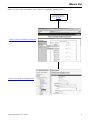
Energy Management Connected Components
Building Block - W.A.G.E.S. Energy Solution
Quick Start
Important User Information
Solid state equipment has operational characteristics differing from those of electromechanical equipment. Safety Guidelines
for the Application, Installation and Maintenance of Solid State Controls (publication SGI-1.1 available from your local Rockwell
Automation sales office or online at http://www.rockwellautomation.com/literature/) describes some important differences
between solid state equipment and hard-wired electromechanical devices. Because of this difference, and also because of the
wide variety of uses for solid state equipment, all persons responsible for applying this equipment must satisfy themselves that
each intended application of this equipment is acceptable.
In no event will Rockwell Automation, Inc. be responsible or liable for indirect or consequential damages resulting from the use
or application of this equipment.
The examples and diagrams in this manual are included solely for illustrative purposes. Because of the many variables and
requirements associated with any particular installation, Rockwell Automation, Inc. cannot assume responsibility or liability for
actual use based on the examples and diagrams.
No patent liability is assumed by Rockwell Automation, Inc. with respect to use of information, circuits, equipment, or software
described in this manual.
Reproduction of the contents of this manual, in whole or in part, without written permission of Rockwell Automation, Inc., is
prohibited.
Throughout this manual, when necessary, we use notes to make you aware of safety considerations.
WARNING
Identifies information about practices or circumstances that can cause an explosion in a hazardous environment,
which may lead to personal injury or death, property damage, or economic loss.
IMPORTANT
Identifies information that is critical for successful application and understanding of the product.
ATTENTION
Identifies information about practices or circumstances that can lead to personal injury or death, property damage,
or economic loss. Attentions help you identify a hazard, avoid a hazard, and recognize the consequence
SHOCK HAZARD
Labels may be on or inside the equipment, for example, a drive or motor, to alert people that dangerous voltage may
be present.
BURN HAZARD
Labels may be on or inside the equipment, for example, a drive or motor, to alert people that surfaces may reach
dangerous temperatures.
Rockwell Automation, Allen-Bradley, Rockwell Software, Powermonitor, Powermonitor 1000, PanelView, PanelView Component, MicroLogix, RSLogix 500, RSEnergyMetrix, RSLinx Classic, and
TechConnect are either trademarks or registered trademarks of Rockwell Automation, Inc.
Trademarks not belonging to Rockwell Automation are property of their respective companies.
Where to Start
Follow the path below to complete your connected components building block.
Connected Components
Building Blocks, publication
CC-QS001
Chapter 1 Powermonitor 1000 Device Configuration
Chapter 2 System Validation and Application Tips
3Publication CC-QS0021A-EN-P - July 2010
3
Where to Start
Notes:
4
Publication CC-QS0021A-EN-P - July 2010
Table of Contents
Preface
Introduction . . . . . . . . . . . . . . . . . . . . . . . . . . . . . . . . . . . . . 7
Conventions Used in This Manual . . . . . . . . . . . . . . . . . . . . . 8
Additional Resources. . . . . . . . . . . . . . . . . . . . . . . . . . . . . . . 8
Chapter 1
Powermonitor 1000 Device
Configuration
Introduction . . . . . . . . . . . . . . . . . . . . . . . . . . . . . . . .
Before You Begin . . . . . . . . . . . . . . . . . . . . . . . . . . . .
What You Need . . . . . . . . . . . . . . . . . . . . . . . . . . . . .
Follow These Steps . . . . . . . . . . . . . . . . . . . . . . . . . . .
Configure a Powermonitor 1000 Device . . . . . . . . . . . .
Configure the Powermonitor 1000 Device Through the
Integrated LCD Interface . . . . . . . . . . . . . . . . . . . . . . .
Additional Resources. . . . . . . . . . . . . . . . . . . . . . . . . .
.
.
.
.
.
.
.
.
.
.
.
.
.
.
.
.
.
.
.
.
. 9
. 9
10
10
11
. . . . 17
. . . . 22
Chapter 2
System Validation and Application Introduction . . . . . . . . . . . . . . . . . . . . . . . . . . . . . . . . . . . . 23
Before You Begin . . . . . . . . . . . . . . . . . . . . . . . . . . . . . . . . 23
Tips
What You Need . . . . . . . . . . . . . . . . . . . . . . . . . . . .
Follow These Steps . . . . . . . . . . . . . . . . . . . . . . . . . .
W.A.G.E.S. Application to PanelView Component
Configuration . . . . . . . . . . . . . . . . . . . . . . . . . . . . . .
W.A.G.E.S. and Powermonitor 1000 Devices to
RSEnergyMetrix Software Configuration . . . . . . . . . . .
Configure Communication Drivers . . . . . . . . . . . . . . .
Configure a Powermonitor 1000 Device . . . . . . . . . . .
Configure a W.A.G.E.S. Device . . . . . . . . . . . . . . . . .
Copy Devices . . . . . . . . . . . . . . . . . . . . . . . . . . . . . .
Creating Powermonitor 1000 (Electric Meter) in
RSEnergyMetrix Software. . . . . . . . . . . . . . . . . . . . . .
Creating W.A.G.E.S (Water Meter) in RSEnergyMetrix
Software . . . . . . . . . . . . . . . . . . . . . . . . . . . . . . . . . .
Additional Resources. . . . . . . . . . . . . . . . . . . . . . . . .
. . . . . 23
. . . . . 24
. . . . . 25
.
.
.
.
.
.
.
.
.
.
.
.
.
.
.
.
.
.
.
.
.
.
.
.
.
33
34
36
38
40
. . . . . 41
. . . . . 47
. . . . . 49
Appendix A
Frequently Asked Questions
5Publication CC-QS0021A-EN-P - July 2010
Introduction . . . . . . . . . . . . . . . . . . . . . . . . . . . . . . . . . . . . 51
5
Table of Contents
Notes:
6
Publication CC-QS0021A-EN-P - July 2010
Preface
Introduction
This quick start is designed to provide a way to implement and use a
connected component for energy management. To assist in the design
and installation of your system, application files and other information
are provided on the Connected Components Building Blocks
Overview CD, publication CC-QR001. The CD provides bills of
materials (BOM), CAD drawings for panel layout and wiring, control
programs, Human Machine Interface (HMI) screens, and more. With
these tools and the built-in best-practices design, the system designer
is free to focus on the design of their machine control and not on
design overhead tasks. The beginning of each chapter contains the
following information. Read these sections carefully before beginning
work in each chapter:
• Before You Begin - This section lists the steps that must be
completed and decisions that must be made before starting that
chapter. The chapters in this quick start do not have to be
completed in the order in which they appear, but this section
defines the minimum amount of preparation required before
completing the current chapter.
• What You Need - This section lists the tools and equipment that
are required to complete the steps in the current chapter. This
includes, but is not limited to, hardware and software.
• Follow These Steps - This illustrates the steps in the current
chapter and identifies the steps required to complete the
examples.
Use this Energy Management Connected Components Building Block
Quick Start in conjunction with the Connected Components Building
Blocks Quick Start, publication CC-QS001.
Refer to Additional Resources on page 8 for a listing of quick starts.
Publication CC-QS0021A-EN-P - July 2010
7
Preface
Conventions Used in This
Manual
This manual uses these conventions.
Convention
Meaning
Example
Check or uncheck
To activate or deactivate a checkbox.
Check Disable Keying.
Click
Click the left mouse button once while the cursor is positioned
on object or selection.
Click Browse.
Select
Use the mouse to highlight a specific option.
Select the New Module folder.
Enter
What you type.
Enter your choice.
>
Use this symbol to indicate the sub-menu name.
Choose File > Menu > Options.
Additional Resources
Resource
Description
Connected Components Building Blocks Quick Start, Provides information on how to select products and gain access to panel and wiring
publication CC-QS001
information.
8
Connected Component Building Blocks Overview
CD, publication CC-QR001
Provides files for the Connected Component Building Blocks.
http://www.ab.com
Provides access to the Allen-Bradley website.
Powermonitor 1000 User Manual,
publication 1408-UM001
Provides information for using the Powermonitor 1000 device.
Powermonitor 1000 Installation Instructions,
publication 1408-IN001
Provides information for installing the Powermonitor 1000 device.
PanelView Component Operator Terminals User
Manual, publication 2711C-UM001
Provides information on using the PanelView Component HMI terminals.
PanelView Component Installation Instructions,
publication 2711C-IN001
Provides installation information for the PanelView Component terminal.
MicroLogix 1100 Programmable Controllers
Installation Instructions, publication 1763-IN001
Provides installation information for the MicroLogix 1100 programmable controller.
MicroLogix 1100 Programmable Controllers User
Manual, publication 1763-UM001
Provides information on using the MicroLogix 1100 programmable controller
RSEnergyMetrix Getting Results Guide, publication
ENEMTX-GR001
Provides information about using RSEnergyMetrix software.
Current Transformer Selection Matrix, publication
1411-SG001
Provides a selection matrix for choosing your current transformer.
http://www.rockwellautomation.com/
knowledgebase
Provides access to self-service support.
http://www.rockwellautomation.com/components/
connected
Provides access to the Connected Components website.
Publication CC-QS0021A-EN-P - July 2010
Chapter
1
Powermonitor 1000 Device Configuration
Introduction
In this chapter, you will learn to configure a Powermonitor 1000 device.
For other configuration parameters such as, Wiring Mode WYE, Delta, Potential/Current
Transformer ratios, Demand periods, and advanced configuration, you need to consult these
Powermonitor 1000 publications:
• Bulletin 1408 Powermonitor 1000 User Manual, publication 1408-UM001
• Powermonitor 1000 Unit Installation Instructions, publication 1408-IN001
Before You Begin
• Review the Energy Management Connected Component Building Blocks common folder to
understand important background information regarding your Powermonitor device and
software package.
• Select hardware and wire your Powermonitor 1000 device. Refer to the Powermonitor 1000
Unit Installation Instructions, publication 1408-IN001, for reference.
Publication CC-QS0021A-EN-P - July 2010
9
Chapter 1
Powermonitor 1000 Device Configuration
What You Need
• Powermonitor 1000 unit
• Current transformers and potential transformers (if required, refer to the Powermonitor 1000
User Manual, publication 1408-UM001)
• Product manuals
– Bulletin 1408 Powermonitor 1000 User Manual, publication 1408-UM001
– Powermonitor 1000 Unit Installation Instructions, publication 1408-IN001
– PanelView Component User Manual, publication 2711C-UM001
Follow These Steps
Follow these paths to configure the Powermonitor device and PanelView Component device in
your energy system management.
Configure a Powermonitor 1000 Device
Start
Configure
Powermonitor 1000
Device Parameters
through a Web
Browser, page 11
Configure the
EtherNet/IP Address,
page 12
Configure Analog
Inputs, page 13
Configure Advanced
Device Parameters,
page 14
Configure the Date
and Time, page 15
Configure the
Powermonitor 1000
Device Through the
Integrated LCD
Interface, page 17
10
Publication CC-QS0021A-EN-P - July 2010
Powermonitor 1000 Device Configuration
Chapter 1
Configure a Powermonitor 1000 Device
This section shows you how to configure parameters of a Powermonitor 1000 device by using the
internal LCD display and configuration web page. Certain settings are needed for the
Powermonitor 1000 device to meter, communicate, and work with RSEnergyMetrix software. You
will set the network configuration, Voltage mode, PT and CT ratios, demand values, and the date
and time. Your application may require additional configuration.
Network configuration is provided for the Powermonitor 1000 device on the Ethernet network. For other
communication options, refer to the Powermonitor 1000 Unit Installation Instructions, publication
1408-IN001.
TIP
Configure Powermonitor 1000 Device Parameters through a Web Browser
Follow these steps to configure Powermonitor 1000 device parameters.
1. Launch the Internet browser on your computer.
2. In the Address field, type the IP address of your Powermonitor 1000 device.
The default IP address is 192.168.254.xxx, where xxx is the unit’s ID. The default address
simplifies the task of making the initial connection to the unit from a personal computer.
http://192.168.254.23
TIP
You can check the IP address of the Powermonitor 1000 device from its display or by
using RSLinx Classic software and configuring an EtherNet/IP driver.
Publication CC-QS0021A-EN-P - July 2010
11
Chapter 1
Powermonitor 1000 Device Configuration
Configure the EtherNet/IP Address
Follow these steps to configure the EtherNet/IP address of a Powermonitor 1000 device.
1. Choose Configure Options>
Communication > Ethernet
Communications to access the
Ethernet Configuration page.
2. Enter the default password of 0 or another
valid password to access Edit mode.
TIP
The password appears as asterisks
(*). If you don’t know the password,
call Rockwell Automation technical
support for assistance.
1
3. Enter appropriate values in the IP Address
Byte fields.
For this example, the IP address is 10.10.10.1
for the first Powermonitor 1000 device.
4. Enter the Subnet Mask and Gateway IP addresses as required.
5. Click Submit to send the parameter changes to the Powermonitor 1000 device.
TIP
You will lose communication to the Powermonitor 1000 device. You must enter the new IP
address in the Address field of your web browser to re-establish communication with the device.
6. Browse to the new IP address from your web browser.
The IP address is shown on the default LCD display screen.
12
Publication CC-QS0021A-EN-P - July 2010
Powermonitor 1000 Device Configuration
Chapter 1
Configure Analog Inputs
Follow these steps to configure the Voltage mode, PT ratios, and CT ratios for the
Powermonitor 1000 device. The Analog Input Set-up Parameters table on page 14 shows the
analog input parameters and example settings.
1. From the Configure Options menu,
choose Analog Input to display the
Analog Input Configuration page.
600
2. Enter the default password of 0 or another
valid password to access Edit mode.
TIP
The password appears as asterisks
(*). If you don’t know the
password, call Rockwell
Automation technical support for
assistance.
3. Enter the value of the Voltage Mode you
are using.
4. Set elements 2, 3, and 4 to configure the
PT and CT parameters.
5. Click Submit to send the parameter changes to the Powermonitor 1000 device.
Publication CC-QS0021A-EN-P - July 2010
13
Chapter 1
Powermonitor 1000 Device Configuration
Analog Input Set-up Parameters
Parameter
Range
Default
Example Settings
Password
0…9999
0
0
Voltage Mode
0…6
0 = Direct Delta
1 = Open Delta
2 = Wye
3 = Single Phase
4 = Demo, simulated results
5 = 1PT1CT-LL
6 = 1PT1CT-LN
2
2
PT Primary
1.0…50,000
480
480
PT Secondary
5.00…50,000
480
480
CT Primary
5.00…50,000
5
600
System PF Setting
0 = Lead (-97…89)
1 = High (-85…98)
2 = Low (-52…-95)
2 = Low
2
Configure Advanced Device Parameters
Follow these steps to configure advanced demand parameters for the Powermonitor 1000 device.
These settings include demand source, demand period length, and the number of demand
periods to average for the demand calculation. The Advanced Device Configuration Parameters
table on page 15 shows the demand parameters and example settings.
1. From the Configure
Options menu, choose
Advanced to access the
Advanced Configuration
page.
2. Enter the default password of 0 or another
valid password to access Edit mode.
TIP
The password appears as asterisks
(*). If you don’t know the password, call
Rockwell Automation technical support
for assistance.
14
Publication CC-QS0021A-EN-P - July 2010
Powermonitor 1000 Device Configuration
Chapter 1
3. Set appropriate values for the demand parameters (elements 14, 15, and 16).
For this example, accept the default parameters as shown.
4. Click Submit to send the parameter changes to the Powermonitor 1000 device.
Advanced Device Configuration Parameters
Parameter
Range
Default
Example Settings
Password
0…9999
0
0
Demand Source
0…3
0 = Internal Timer
1 = Status Input 2
2 = Controller Command
3 = Ethernet Demand Broadcast
0
0
Demand Period Length
0…99 min
15 min
15
Number of Demand Periods
1…15
1
1
Forced Demand Sync Delay
0…90 s
10
Demand Broadcast Master Select
0…1
0
Broadcast Port Number
(Ethernet Setup)
300…400
300
Configure the Date and Time
Follow these steps to configure the date and time for the Powermonitor 1000 device. The Date
and Time Set-up Parameters table on page 16 shows the date and time parameters, and example
settings.
1. From the Configure Options
menu, choose Date and Time to
access the Date and Time
Configuration page.
Publication CC-QS0021A-EN-P - July 2010
15
Chapter 1
Powermonitor 1000 Device Configuration
2. Enter the default password of 0 or another
valid password to access Edit mode.
The password appears as asterisks (*).
If you don’t know the password, call
Rockwell Automation technical support
for assistance.
TIP
3. Configure the date and time parameters
accordingly.
4. Click Submit to send the parameter changes
to the Powermonitor 1000 device.
Date and Time Set-up Parameters
Parameter
Range
Default
Example Settings
Password
0…9999
0
0
Date: Year
2001…2100
2005
Date: Month
1…12
1
Date: Day
1…31
0
Time: Hour
0…23
0
Time: Minute
0…59
0
Time: Seconds
0…59
0
Time: Hundredths 0…59
0
TIP
16
For a full Powermonitor 1000 LCD screen display and configuration map, see pages 30…32 of the
Powermonitor 1000 Installation Instructions, publication 1408-IN001.
Publication CC-QS0021A-EN-P - July 2010
Powermonitor 1000 Device Configuration
Chapter 1
Configure the Powermonitor 1000 Device Through the Integrated LCD
Interface
The Powermonitor 1000 device has an onboard LCD for viewing and configuration. Buttons are
provided to control the display. The display has three modes of operation.
• Display mode lets you select and view parameters including metering, event log, and selftest information.
• Program mode lets you change configuration parameters, with security against
unauthorized configuration changes. Each Powermonitor 1000 device is password
protected.
• Edit mode lets you modify the selected parameters. In Edit mode, a highlight cursor
appears under the value of the parameter being modified, starting at the right-hand (least
significant) digit.
The diagram and table shows the LCD
interface buttons and their functions.
The buttons function differently in each mode.
The power monitor enters into Display mode
by default.
Up Arrow
RS-485
RX
TX
STATUS
Powermonitor 1000
Mod Net
Down Arrow
Button
Escape
Enter
Mode
Display
Program
Edit
Escape
Returns to parent menu
At top menu, selects default screen
Cancels changes to the parameter and returns
to Program mode
Up arrow
Steps back to the previous parameter or menu item
Increments the value of the highlighted digit
Down arrow
Steps forward to the next parameter or menu item
Decrements the value of the highlighted digit
Enter
Steps into a sub-menu or sets
default screen
Steps into a sub-menu, selects the
parameter to be modified or
changes to Edit mode
Saves the parameter change and returns to
Program mode
Up and down
arrows together
Refreshes the display
No effect
Moves the highlight cursor one character to
the left
User choices for display and configuration are organized in a hierarchical menu system within the
Powermonitor 1000 device.
Publication CC-QS0021A-EN-P - July 2010
17
Chapter 1
Powermonitor 1000 Device Configuration
This diagram shows how to navigate in the display and configuration menu.
Chart Key
Default
Screen
Level 1
Level 2
Next Item
(within current level)
Level 3
Level 4
Previous Item
(within current level)
Select
LCD Screen Display and Configuration Menu Map
The Powermonitor 1000 device lets you select and navigate to a default screen. The default
screen displays at startup and is displayed after the display has been dormant for approximately
30 minutes.
To set the current screen as the default, press Enter and click Yes.
If you’re in another menu and want to get back to the default screen, continue pressing Escape
until you are prompted ‘To Default Screen?’ Click Yes to display the default screen.
18
Publication CC-QS0021A-EN-P - July 2010
Powermonitor 1000 Device Configuration
Chapter 1
Main Menu, Page 1
Default
Screen?
Level 1
Display
Program
Password?
Level 2
Display
Config
Setup
Display
Metering
Level 3
Metering Volts
Amps
Frequency(1)
Metering
Power(1)(2)
Metering
Energy(1)
PF 1
PF 2
PF 3
PF Total
KW 1
KW 2
KW 3
KW Total
KVAR 1
KVAR 2
KVAR 3
KVAR Total
KVA 1
KVA 2
KVA 3
KVA Total
Status 1 Cnt
Status 2 Cnt
kWH Fwd
kWH Rev
kWH
kVARH Fwd
kVARH Rev
kVARH
kVAH
kW Demand
kVAR Demand
kVA Demand
PF Demand
kW Proj Demand
kVAR Proj Demand
kVA Proj Demand
See Setup
Submenu
Level 4
I1
I2
I3
I Average
V LN1
V LN2
V LN3
V L12
V L23
V L31
V LN Avg
V LL Avg
Frequency
Unbalance V
Unbalance I
(1) The Catalog Number and Voltage mode
determine which parameters are displayed.
(2)
Individual phase parameters are not
displayed in Delta modes.
Main Menu, Page 2
Level 2
Display Wiring
Diagnostics
Display Run
Status
Display I/O
Status
Program
Commands
Program
Setup
Wiring Status
Volts Input Missing
Volts Input Inverted
Amps Input Missing
Amps Input Inverted
Voltage Rotation
Amps ROtation
VOlts Ph1 Angle
Volts Ph1 Magnitude
Volts Ph2 Angle
Volts Ph2 Magnitude
Volts Ph3 Angle
Volts Ph3 Magnitude
Amps Ph1 Angle
Amps Ph1 Magnitude
Amps Ph2 Angle
Amps Ph2 Magnitude
Amps Ph3 Angle
Amps Ph3 Magnitude
Series Number
Catalog Number
Comm Type
WIN Number
Application FRN
Boot Code FRN
Default Device ID
Accuracy Class
Overall Status
Flash Memory
SRAM Memory
NVRAM Memory
SPI Interface
Real Time Clock
Watchdog Timer
Metering Status
LCD Interface
Serial Interface
Ethernet Interface
Input Over Range
Phase Loss Detection
Terminals Locked
Date
Time
KYZ Status
S1 Status
S1 Status Count
S2 Status
S2 Status Count
Output Word
Clear kWh Registers
Clear kVARh Registers
Clear kVAh Registers
Clear Energy All
Registers
Clear Status 1 Count
Clear Status 2 Count
Force KYZ On
Force KYZ Off
Remove KYZ Force
Restore Defaults
Test Wiring Connections
Reset System
Clear Min/Max Log
Perform Wiring Diagram
Store Load Factor
Record
Clear Load Factor Log
Store TOU Record
Clear TOU Log
Troubleshooting Password
See Setup
Submenu
Level 3
Publication CC-QS0021A-EN-P - July 2010
19
Chapter 1
Powermonitor 1000 Device Configuration
Setup Submenu
Configuration Mode
Level 2 Program Mode, Level 3 Display Mode
Analog Input
Advanced
RS485
Ethernet
New Password
Date
Time
Meter Averaging
DST Enable
DST Start
Month, Wk, Day
DST Start Hour
DST End
Month, Wk, Day
DST End Hour
KYZ Output Select
KYZ Output Scale
KYZ Pulse Duration
Status 1 Input Scale
Status 2 Input Scale
Demand Source
Demand Length
Demand Periods
Demand Sync Delay
Unit Error Action
Error Log Full Action
LCD Display Contrast
Protocol Setting
Serial Delay mS
Baud Rate
Serial Address
Serial Data Format
Inter Character
Timeout
Max Node Address
IP Address Byte a
IP Address Byte b
IP Address Byte c
IP Address Byte d
Subnet Mask Byte a
Subnet Mask Byte b
Subnet Mask Byte c
Subnet Mask Byte d
Gateway Byte a
Gateway Byte b
Gateway Byte c
Gateway Byte d
SNTP Mode Select
SNTP Update Rate
SNTP Time Zone
Time Server Byte a
Time Server Byte b
Time Server Byte c
Time Server Byte d
Broadcast Mode
Broadcast Port
Level 3, 4
Voltage Mode
PT Primary
PT Secondary
CT Primary
System PF Setting
Edit a Parameter
To edit a parameter:
• press <up> or <down> to change the highlighted digit.
• press <up> and <down> together to move the highlight cursor one place to the left, and
press <up> or <down> to set the selected digit’s value.
Continue in the same way until the correct value is entered, then press <enter> when done.
Setup Example
This example steps through setting the unit date to demonstrate use of the display and buttons to
navigate through the setup menu and make changes to parameters.
1. Navigate to the initial screen.
The screen shown is the top level
screen. If it is not present, press
<escape> until it appears.
RS-485
RX
TX
STATUS
Powermonitor 1000
Mod Net
Power And
Energy Management
Solutions
If you press <escape> once too
often, the ‘To Default Screen?’
message appears. Press <escape>
once more if this occurs.
20
Publication CC-QS0021A-EN-P - July 2010
Powermonitor 1000 Device Configuration
2. Press <enter> and this screen
appears.
RS-485
RX
STATUS
TX
Chapter 1
Powermonitor 1000
Mod Net
Display
3. Press <up> or <down> once,
Program appears in the display,
then Press <enter>.
RS-485
RX
4. Press <enter> if the password has
not been changed from the default
(0000).
STATUS
TX
Powermonitor 1000
Mod Net
Password
o
0000
If the password has been changed,
then enter the correct password.
When the correct password is
entered, Program Setup appears
in the display. The
Powermonitor 1000 device is now
in Program mode.
RS-485
RX
STATUS
TX
Powermonitor 1000
Mod Net
Program
Setup
If an incorrect password is
entered, Invalid Password
appears. Press any button to try
again.
5. Press <enter>.
Analog Input appears in the
display. Press <down>.
RS-485
RX
TX
STATUS
Powermonitor 1000
Mod Net
Advanced
Setup
Publication CC-QS0021A-EN-P - July 2010
21
Chapter 1
Powermonitor 1000 Device Configuration
6. With Advanced Setup displayed,
press <enter>, then press
<down> until Set Date Year
appears.
RS-485
RX
TX
STATUS
Powermonitor 1000
Mod Net
Set Date
Year
7. Press <enter> to change the value
of the year.
The Powermonitor 1000 device is
now in Edit mode, indicated by
the presence of the highlight
cursor. Change the year value and
press <enter> to save it or
<escape> to discard changes.
2008
RS-485
RX
TX
STATUS
Powermonitor 1000
Mod Net
Set Date
Year
20058
See Edit a Parameter, page 20 if
you need help with this.
8. Select the next item in the configuration menu by pressing <down>.
Set the month in the same way.
9. Continue setting the remaining parameters in the same way.
a. Navigate to the top menu display.
b. Press <enter> then <down> then <enter> to access the password screen.
c. Enter the correct password to access Program mode.
d. Navigate to the desired menu using <enter>, <up> and <down>.
e. Press <enter> selects a parameter for editing.
f. Press <up> or <down> increments or decrements the value of the highlighted digit.
g. Press <up> and <down> together move the highlight cursor.
h. Press <enter> saves your changes; <escape> discards them.
i. Press <escape> several times to the top menu to access Display mode.
Additional Resources
Refer to page 8 for a listing of product and information resources.
22
Publication CC-QS0021A-EN-P - July 2010
Chapter
2
System Validation and Application Tips
Introduction
In this chapter, you will configure the communications for your application. You will learn how
to do the following:
• Connect a MicroLogix Controller (W.A.G.E.S.) to a PanelView Component terminal.
The W.A.G.E.S. controller supports up to 10 discrete inputs, 4 analog inputs, and 2
Powermonitors on an Ethernet network.
• Configure RSEnergyMetrix software to log your Powermonitor 1000 device data and the
W.A.G.E.S. controller data.
Before You Begin
• Review the MicroLogix 1100 User Manual, publication 1763-UM001
• Review the PanelView Component User Manual, publication 2711C-UM001
• Optional - Install RSEnergyMetrix software (Review the RSEnergyMetrix User and
Installation Manual, publication ENEMTX-GR001)
• Configure Powermonitor 1000 devices, refer to Chapter 1
• Configure the PanelView Component terminal
What You Need
• MicroLogix 1100 controller hardware and RSLogix 500 software for downloading the
W.A.G.E.S. program to the controller connected over the same Ethernet network as the
PanelView Component terminal and the Powermonitor 1000 device
• Powermonitor 1000 device
• PanelView Component 600 Touch terminal
• USB flash drive (for loading the PanelView application)
• Personal computer with Internet access for launching and using RSEnergyMetrix software
• RSEnergyMetrix CD, catalog number 9307-ENEMTXCD
• RSEnergyMetrix online help and Getting Results Guide, publication ENEMTX-GR001
23Publication CC-QS0021A-EN-P - July 2010
23
Chapter 2
System Validation and Application Tips
Follow These Steps
Follow these steps to verify that communication is occurring between your devices.
Copy Devices
Start
page 40
W.A.G.E.S. Application to
PanelView Component
Configuration
page 25
Creating Powermonitor
1000 (Electric Meter) in
RSEnergyMetrix Software
page 41
PanelView Component C600
Screens Quick Navigation
for W.A.G.E.S. Energy
Solution
page 27
Customize Your
PanelView Component
Application
page 30
W.A.G.E.S. and
Powermonitor 1000
Devices to
RSEnergyMetrix Software
Configuration
page 33
Configure Communication
Drivers
page 34
Configure a Powermonitor
1000 Device
page 36
Configure a W.A.G.E.S.
Device
Create a Powermonitor
1000 Electric Meter
page 41
Assign Meter Tags to a
Powermonitor 1000
Electric Meter
page 43
Copy Meters and Tags For
a Powermonitor 1000
Device
page 45
Creating W.A.G.E.S
(Water Meter) in
page 47
Create a W.AG.E.S Water
Meter
page 47
Assign Meter Tags to a
W.A.G.E.S. Water Meter
page 48
page 38
24
Publication CC-QS0021A-EN-P - July 2010
System Validation and Application Tips
Chapter 2
W.A.G.E.S. Application to PanelView Component Configuration
Loading W.A.G.E.S. Energy Solution Application to PanelView Component Terminal
Follow these steps to download the 'WAGES' preconfigured HMI project to the 6-inch touch
(color) PanelView Component terminal. This application includes viewable metering information
from the W.A.G.E.S. controller. This W.A.G.E.S. controller has capability for up to 10 discrete
inputs, 4 analog inputs, and 2 Powermonitors on an Ethernet network.
1. Power up the MicroLogix 1100 controller (W.A.G.E.S.).
2. Power up the PanelView Component 6 inch touch (color) terminal.
TIP
The PanelView Component terminal is powered with a 24V DC supply. The PanelView Component HMI
power wiring is illustrated in the Connected Building Block CD.
W.A.G.E.S.
Controller
3. Verify that the W.A.G.E.S. controller and Powermonitor 1000 units (up to two in this
application) are online, and reside on the same network as the PanelView C600 terminal.
The PanelView C600 application is preconfigured for the W.A.G.E.S. controller IP address of
192.168.0.100.
The Controller is configured to message only two Powermonitor 1000 devices with default
IP addresses of 192.168.0.101 and 192.168.0.102.
Publication CC-QS0021A-EN-P - July 2010
25
Chapter 2
System Validation and Application Tips
The PanelView Component terminal can be configured for any IP address in the
192.168.0.xxx range to communicate with W.A.G.E.S. devices.
The IP address for the W.A.G.E.S. controller can be changed in the PanelView Component
design environment.
4. Download your program to your MicroLogix controller:
• If you have discrete and analog inputs, then download
WAGES ML1100 REV 1 with Digital and Analog.RSS program.
• If only discrete meters are desired, then download
WAGES ML1100 REV 1 with Digital ONLY.RSS program.
TIP
Your controller must be in the same subnet/gateway as the PanelView Component HMI terminal.
TIP
Review the PanelView Component HMI Terminals User Manual, publication 2711C-UM001, for
instructions to update a PanelView Component HMI project in the design environment.
5. Copy the PanelView Component application ‘WAGES.cha’ from the Component Building
Block CD to the root of a USB flash drive.
6. Plug in the USB flash drive to the PanelView Component terminal.
The USB connection is on the back side of PanelView C600 terminal.
TIP
This application was developed for a PanelView Component 6 inch touch screen unit only. To transfer
the application to the PanelView Component terminal, see the PanelView Component HMI Terminals
Quick Start, publication 2711C-QS001.
Go to Config > File Manager > Source (USB) > Selected WAGES.cha file, and copy it to the internal
memory of the PanelView Component terminal.
7. Configure the Screensaver/Start-up application as desired from the PanelView Component
HMI settings, then run the W.A.G.E.S. Energy Solution application file.
8. Verify that the PanelView Component terminal is reading data from the W.A.G.E.S.
controller.
26
Publication CC-QS0021A-EN-P - July 2010
System Validation and Application Tips
Chapter 2
This flowchart shows the PanelView Component terminal screen navigation.
PanelView Component C600 Screens Quick Navigation for W.A.G.E.S. Energy Solution
These images show the navigation
through the PanelView Component
terminal.
Home Screen
Clicking each button provides navigation
to the W.A.G.E.S. configuration and
metering screens.
Publication CC-QS0021A-EN-P - July 2010
27
Chapter 2
System Validation and Application Tips
This screen shows the naviagation to the
configuration screen. The default login
is:
user: admin
password: admin
W.A.G.E.S. Configuration
W.A.G.E.S. Configuration
This screen lets you configure the meter
scaling. Enter the value of how much
each pulse weighs. For example, enter
100 for the input if a discrete water meter
transmits a pulse after using 50 gallons of
water. This is because the W.A.G.E.S.
discrete inputs increment consumption
on any change of state. So, 50 gal for low
to high and 50 gal for high to low
transmits a pulse.
Meters in the left column, from top to
bottom, represent meters 0…4 wired to
the MicroLogix 1100 controller inputs.
Meters in the right column represent
meters 5…9 wired to the MicroLogix 1000 controller inputs.
28
Publication CC-QS0021A-EN-P - July 2010
System Validation and Application Tips
This screen shows the consumptions of
the discrete (W.A.G.E.S.) meters
W.A.G.E.S. Metering
This configuration screen lets you
configure analog meter scaling.
W.A.G.E.S. Analog Meter Configuration
Chapter 2
For example, if your air meter is a
4…20 mA for 100 MCF, enter 0 MCF for
Low Engineering Value, and 100 MCF for
High Engineering Value.
TIP
Analog flow rate should be
converted to rate per hour and
that is the High Engineering Value.
The default PLC configuration in the
building block PLC code is 4…20 mA for
the analog module. It can also be
configured as a -10…10V signal.
The top row is analog input 1 and the bottom row is analog input 4.
Publication CC-QS0021A-EN-P - July 2010
29
Chapter 2
System Validation and Application Tips
Customize Your PanelView Component Application
The text (Units, W.A.G.E.S. Meter names) and IP address of the W.A.G.E.S. device can be
configured through the design environment.
TIP
For complete customization processes, see the PanelView Component HMI
Terminals Quick Start, publication CC-QS001.
1. To change the IP address of a W.A.G.E.S. device in your PanelView Component application,
you must first connect to the Panelview Component terminal through a web browser.
Use Mozilla FireFox, version 2.x or later, or Internet Explorer, version 7.0 or later, web
browsers.
2. Type the IP address of your PanelView Component terminal.
3. On the home page, select the W.A.G.E.S. application and click Edit.
IMPORTANT
Make sure the pop ups are not blocked, as it will launch a new window.
4. Click the
Communication tab
and change the IP
address as needed.
30
Publication CC-QS0021A-EN-P - July 2010
System Validation and Application Tips
Chapter 2
5. To customize meter labels, click the Screens tab.
The default screen is W.A.G.E.S. Metering 1 Pulse.
6. Select the meter you would like
to change, then click the
appearance drop down box,
and change the text.
7. Edit the meter's units if needed.
Remember to change to
corresponding information in
the configuration screen. This
information will not
automatically update.
Publication CC-QS0021A-EN-P - July 2010
31
Chapter 2
System Validation and Application Tips
8. In this example, navigate to
W.A.G.E.S. Metering 1
Configuration to change the
name of the same meter from
steps 6 and 7.
Similarly, the W.A.G.E.S.
Metering 2 meter names and
units can be changed.
Remember to change the
names in the W.A.G.E.S.
Metering 2 Configuration
screen and units for any meter
name you change. For
W.A.G.E.S. Metering 2,
remember to update the
corresponding flow trend
screens to reflect your changes.
9. After changes have been made, click the Validate Application button on the menu bar, then
save and close the application.
32
Publication CC-QS0021A-EN-P - July 2010
System Validation and Application Tips
Chapter 2
W.A.G.E.S. and Powermonitor 1000 Devices to RSEnergyMetrix Software
Configuration
Overview of Devices
Devices are physical entities that RSEnergyMetrix software communicates with over a network.
Setting up a device in RSEnergyMetrix software establishes communication and creates database
definitions for the device.
Devices may be directly connected to the server over a network if the RSEnergyMetrix server is
also on the network through an appropriate network interface and you have configured the
appropriate RSLinx Classic device drivers. Devices routed through a ControlLogix gateway or
RSLinx Classic gateway are also considered directly connected devices.
Device Classes
RSEnergyMetrix software uses device classes to determine how to interact with a particular
device. The device class includes the device family, communication type, and specifies whether
the device has a clock that can be synchronized. The device classes covered in this quick start
include a Powermonitor 1000 device and a W.A.G.E.S. (MicroLogix 1100) controller.
For a complete list of device classes, refer to:
• RSEnergyMetrix Getting Results Guide, publication ENEMTX-GR001.
• RSEnergyMetrix Online Help provided with RSEnergyMetrix software.
Publication CC-QS0021A-EN-P - July 2010
33
Chapter 2
System Validation and Application Tips
Configure Communication Drivers
Before setting up devices, you need to configure the drivers required for communication. This
example uses the RSLinx Classic Ethernet driver for the Powermonitor 1000 device.
Configure the RSLinx Classic Ethernet Driver
Follow these steps to configure the RSLinx Classic Ethernet driver.
1. Open RSLinx Classic software by
clicking its icon in the Windows
system tray (SysTray).
2. From the Communications menu,
choose Configure Drivers.
3. From the Available Driver
Types pull-down menu,
choose Ethernet Devices.
4. Click Add New.
5. Click OK to accept the default
driver AB_ETH-1.
34
Publication CC-QS0021A-EN-P - July 2010
System Validation and Application Tips
Chapter 2
6. Enter the IP address of your first
device (station).
7. Click Add New to enter the IP
address for each additional device
you want to add, then click OK.
8. Click OK when done entering IP
addresses.
9. Click Close to exit the Configure
Drivers dialog box.
Publication CC-QS0021A-EN-P - July 2010
35
Chapter 2
System Validation and Application Tips
Configure a Powermonitor 1000 Device
Follow these steps to configure a Powermonitor 1000 device.
1. Expand the Devices folder
on the System tab.
2. Navigate to and select the
appropriate group or
domain.
In this example, select the
Electricity group under the
Engineering subdomain.
3. Click the Add a device link.
4. From the Parent group pulldown menu, choose a
subdomain or group.
For this example, choose
Electricity.
5. Check the boxes as shown.
The checkboxes vary by
device type.
If the device will not be
connected during
configuration, clear the Enable
device checkbox to avoid
timeout errors.
Device password applies only to the
Powermonitors. The default of zero matches
the default power monitor password
6. From the Device class pulldown menu, choose a device.
For this example, choose
Powermonitor 1000 (EM3) on
EtherNet/IP.
7. Enter a name for the device.
For this example, enter Boiler House.
8. Enter the Time zone and Time sync interval.
Devices with internal clocks may be time-synched, such as Powermonitor devices and
controllers.
36
Publication CC-QS0021A-EN-P - July 2010
System Validation and Application Tips
Chapter 2
9. Enter the communication path
to the device.
For this example, the
communication path to the first
Powermonitor 1000 EM3 device
is AB_ETH-1\10.10.10.1.
10. Modify other communication settings as needed.
For details, refer to the RSEnergyMetrix software help.
11. Click Save.
The Boiler House device appears
under Electricity.
12. If the device is connected to the network,
click Test Connection to verify
communication with the device.
If you see ‘connection failed’, try again. If the test times out, check that you entered the
correct communication path in step 9 and that the device is online. Try to access the
Powermonitor device's web page or try to ping it from the RSEnergyMetrix server.
Publication CC-QS0021A-EN-P - July 2010
37
Chapter 2
System Validation and Application Tips
Configure a W.A.G.E.S. Device
Follow these steps to configure a W.A.G.E.S. device.
1. Expand the Devices folder
on the System tab.
2. Navigate to and select the
appropriate group or
domain.
In this example, select the
Electricity group under the
Engineering subdomain.
3. Click the Add a device link.
4. From the Parent group pulldown menu, choose a
subdomain or group.
For this example, choose
WAGES.
5. Check the boxes as shown.
The checkboxes vary by
device type.
If the device will not be
connected during
configuration, clear the Enable
device checkbox to avoid
timeout errors.
6. From the Device class pulldown menu, choose a device.
For this example, choose
Ethernet Energy Module
(MicroLogix) on Ethernet.
7. Enter a name for the device.
For this example, enter WAGES.
8. Enter the Time zone and Time sync interval.
Devices with internal clocks may be time-synched, such as Powermonitor devices and
controllers.
38
Publication CC-QS0021A-EN-P - July 2010
System Validation and Application Tips
Chapter 2
9. Enter the communication path to the device.
For this example, the communication path to the first W.A.G.E.S. device is
AB_ETH-1\10.90.172.107.
10. Modify other communication settings as needed.
For details, refer to the RSEnergyMetrix software help.
11. Click Save.
12. If the device is connected to the network, click Test Connection to verify communication
with the device.
If you see ‘connection failed’, try again. If the test times out, check that you entered the
correct communication path in step 9 and that the device is online. Try to access the
Powermonitor device's web page or try to ping it from the RSEnergyMetrix server.
Publication CC-QS0021A-EN-P - July 2010
39
Chapter 2
System Validation and Application Tips
Copy Devices
Follow these steps to create additional devices by using the copy function. For the Efficient
Industries Plant 1 example, you will use the copy function to create five remaining Powermonitor
1000 devices (Power House, Production 1, Production 2, Shipping/Receiving/DC, MCC2).
1. Select an existing device,
and then click Copy.
For this example, select
the Boiler House device.
2. Change the name of the
copied device.
For this example, replace 'Copy of
Boiler House' with ‘Power House’.
3. Change the Communication path to
match the device for this example.
4. If the device will not be connected
during configuration, clear the
Enable device checkbox to avoid
timeout errors.
5. Click Save.
The Power House device
appears under Electricity.
40
Publication CC-QS0021A-EN-P - July 2010
System Validation and Application Tips
Chapter 2
6. For this example, repeat step 1 through step 5 to copy the remaining Powermonitor 1000
devices.
Change the name and communication path to each device as shown in the table. Note that
all devices fall under the Electricity parent group except for the MCC 2 device that is under
Fuels.
Parent Group
Name
Communication Path
Electricity
Production 1
AB_ETH-1\10.10.10.3
Electricity
Production 2
AB_ETH-1\10.10.10.4
Electricity
Shipping/Receiving/DC
AB_ETH-1\10.10.10.5
Fuels
MCC 2
AB_ETH-1\10.10.10.6
Six Powermonitor 1000
devices and one
Powermonitor 3000 device
appear under the
appropriate groups.
PM 1000
This is the Powermonitor 3000 device.
PM 1000
PM 1000
PM 1000
PM 1000
PM 1000
Creating Powermonitor 1000 (Electric Meter) in RSEnergyMetrix Software
You will now create meters for Powermonitor 1000 devices
and assign tags to those meters.
Create a Powermonitor 1000 Electric Meter
Follow these steps to create a Powermonitor 1000 electric
meter.
Publication CC-QS0021A-EN-P - July 2010
Electricity (Group)
Boiler House (PM 1000)
Power House (PM 1000)
Production 1 (PM 1000)
Production 2 (PM 1000)
Shipping/Receiving DC (PM 1000)
41
Chapter 2
System Validation and Application Tips
1. Click the Meters tab.
2. Navigate to and select a
group to assign the meter.
For this example, select
Electricity under the
Engineering subdomain.
3. Click the Meters tab on
the right.
4. Click the Add a new
meter link.
5. From the Parent group pull-down
menu, choose a subdomain or
group.
For this example, choose
Electricity.
6. From the Type pull-down menu,
choose the meter type.
For this example, choose Electric.
7. From the Device pull-down
menu, choose the device
associated with the meter.
For this example, choose
Boiler House.
8. Enter a meter name.
For this example, enter Boiler House Meter.
9. Click Save.
10. Confirm the meter was
created in the correct group.
42
Publication CC-QS0021A-EN-P - July 2010
System Validation and Application Tips
Chapter 2
Assign Meter Tags to a Powermonitor 1000 Electric Meter
You will now assign tags to a Powermonitor 1000 electric meter. For this example, Real Energy
Net, Reactive Energy Net, and Real Power Demand are assigned to the Boiler House Meter.
1. Select the meter to assign tags.
For this example, select Boiler House Meter.
2. Click the Meter Setup tab.
3. Click the Add a new meter
tag link.
4. Verify that the Meter tag type is Device.
5. From the Meter tag type pull-down
menu, choose Real Energy Net.
For a Powermonitor device, the rest of
the settings are autofilled.
Do not change these autofill values.
Changing the values may prevent
logging of the tag or cause incorrect
data to be logged.
The log rate is set to the default log rate
of the meter’s assigned group. It is
typically the utility demand interval
rate.
Refer to the RSEnergyMetrix software
help before changing the log rate or
maximum consumption per hour.
6. Click Save.
Publication CC-QS0021A-EN-P - July 2010
43
Chapter 2
System Validation and Application Tips
7. Click Add when the screen
refreshes.
8. Repeat step 4 through step 7 to add the remaining tags:
• Reactive Energy Net
• Real Power Demand
These are typical tags for electric meters.
9. When done, click the Return to
meter screens link or the meter tag.
The tags just entered
appear on the Meter
Setup tab.
For this example, these
tags appear.
10. Click the Meter Data tab to verify
that the meter data is being
logged.
The data will not appear until the
next logging interval has occurred.
Another way to check the data is
to return to the Meter Setup tab
and click the Read device tags link
just above the list of meter tags.
You can click Current Date/Time
to refresh the data.
44
Publication CC-QS0021A-EN-P - July 2010
System Validation and Application Tips
Chapter 2
Copy Meters and Tags For a Powermonitor 1000 Device
Meters with the same device class and tags can be copied. It’s a real time saver to create the first
meter and its tags, then use the copy function to create the rest of the meters.
For this example, the Powermonitor 1000 electric meters all
use the Real Energy Net, Reactive Energy Net, and Real
Power Demand tags. You will copy the Boiler House meter
and tags to create the Power House, Production 1,
Production 2, and Shipping/Receiving/DC electric meters.
The tags are copied with the meter.
Electricity (Group)
Electric Main (PM 3000)
Boiler House (PM 1000)
Power House (PM 1000)
Production 1 (PM 1000)
Production 2 (PM 1000)
Shipping/Receiving/DC (PM 1000)
Data Center (OPC Server)
1. Select the meter to copy.
For this example, select Boiler
House under the Electricity group.
2. Click the Meter Setup tab.
3. Click Copy.
A copy of the meter is
created under the selected
group with the name
'Copy of Boiler House
Meter'.
Publication CC-QS0021A-EN-P - July 2010
45
Chapter 2
System Validation and Application Tips
4. Change the device to Power
House.
5. Change the meter name to
Power House Meter.
6. Click Save.
The copied meter and its tags
are created under the Electricity
group with the new name.
7. Repeat step 1 through step 6, copy the rest of the Powermonitor 1000 electric meters.
The Real Energy Net, Reactive Energy Net, and Real Power Demand tags are automatically
copied with each device.
8. Change the device name and meter name as shown in the table.
Meter
Parent Group
Device
Name
Production 1
Electricity
Production 1
Production 1 Meter
Production 2
Electricity
Production 2
Production 2 Meter
Shipping/Receiving/DC
Electricity
Shipping/Receiving/DC
Shipping/Receiving/DC Meter
For this example, the electric meter listing looks
like this.
TIP
46
Remember that the device class must be the
same in the source and copied meters,
otherwise the meter tag addressing will be
incorrect in the copied meter.
Copied Meters
Publication CC-QS0021A-EN-P - July 2010
System Validation and Application Tips
Chapter 2
Creating W.A.G.E.S (Water Meter) in RSEnergyMetrix Software
Create a W.AG.E.S Water Meter
Follow these steps to create a W.A.G.E.S. water meter.
1. Click the Meters tab.
2. Navigate to and select a
group to assign the meter.
For this example, select
Water under the
Engineering subdomain.
3. Click the Meters tab on
the right.
4. Click the Add a new
meter link.
5. From the Parent group
pull-down menu, choose
your parent group.
For this example, Choose
Water.
6. From the Type pull-down
menu, choose the meter
type.
For this example, choose
Water.
7. From the Device pulldown menu, choose the
device associated with the
meter.
For this example, choose
WAGES.
8. Enter a meter name.
For this example, enter Water.
9. Click Save.
10. Confirm the meter was created in the correct group.
Publication CC-QS0021A-EN-P - July 2010
47
Chapter 2
System Validation and Application Tips
Assign Meter Tags to a W.A.G.E.S. Water Meter
You will now assign tags to a W.A.G.E.S. water meter.
1. Select the meter to assign tags.
For this example, select Water Meter Consumption.
2. Click the Meter Setup tab.
3. Click the Add a new meter
tag link.
4. Verify that the Meter tag type is Device.
5. From the Value type pull-down menu,
choose Water Usage.
If there is not a value type here, you
have to define value type, and click
the consumption type in the setup.
Go to the System Tab > Unit Setup >
Value Types
6. Click Save.
In this example, the discrete input 1
would be F101 and discrete input 10
would be F110 on the MicroLogix
1100 controller. Element 10 is always
consumption in this PLC code.
Therefore, F101:10 is the
consumption value of discrete input 1.
The analog input 1 would be F111:10 and analog input 4 be F114:10.
7. Click Add when the screen
refreshes.
48
Publication CC-QS0021A-EN-P - July 2010
System Validation and Application Tips
Chapter 2
8. When done, click the Return to
meter screens link or the meter tag.
The tags just entered appear on the Meter Setup tab.
9. Click the Meter Data tab to verify that the meter data is being logged.
The data will not appear until the next logging interval has occurred.
Another way to check the data is to return to the Meter Setup tab and click the Read device
tags link just above the list of meter tags.
You can click Current Date/Time to refresh the data.
Additional Resources
Refer to page 8 for a listing of product and information resources.
Publication CC-QS0021A-EN-P - July 2010
49
Chapter 2
System Validation and Application Tips
Notes:
50
Publication CC-QS0021A-EN-P - July 2010
Appendix
A
Frequently Asked Questions
Introduction
This appendix provides some frequently asked questions regarding using a Powermonitor 1000
device and a PanelView Component HMI terminal.
1. When I click the Navigation links in the PanelView Component HMI, why doesn’t it bring
up the correct display?
A: Calibrate the touch screen on your PanelView Component HMI. Detailed instructions to
re-calibrate the touch screen can be found in the PanelView Component HMI User
Manual, publication 2711C-UM001. (Refer to Additional Resources on page 8.)
2. What does ‘Data Access Error for Alias…’ mean? (My terminal does not refresh and the data
fields are filled with ‘*’.)
A: Check the communication media (Ethernet Cat-5 cable). Verify proper wiring, and
communication protocol settings on your PanelView Component HMI, MicroLogix
controller, and Powermonitor 1000 device (IP addresses, default gateway, subnet mask).
3. I see some of the data for the metering parameters, but it shows ‘*’ on the least significant
digit. What is causing that?
A: The metering parameter in the PanelView Component application is programmed with a
fixed number of digits. Your data value is outside of the fixed digits. You need to
customize the PanelView Component application for your specific situation.
4. When I change screens in my PanelView Component application, I see astericks in some of
the data boxes for a few seconds, but then the values become numbers. Why is this
happening?
A: The default application is set for a 500 ms update rate for all tags. You can change the
configuration to 50 ms in the design environment to improve performance.
5. What is the controller platform for this building block?
A: The controller platform is the MicroLogix 1100 controller, although you can upgrade to
the MicroLogix 1400 controller.
51Publication CC-QS0021A-EN-P - July 2010
51
Appendix A
Frequently Asked Questions
6. What is the roll-over for the discrete and analog meters?
A: The roll-over is 10 million.
7. What is the difference between digital meter, pulse meter, and discrete meter?
A: These all are interchangeable terms for this building block.
8. I don't see any extra modules for the discrete meter. Where is it wired to?
A: This building block uses the MicroLogix 1100 controller on board discrete inputs.
9. For a discrete meter, how is the pulse weight defined for consumption?
A: Consumption is increased by the amount of pulse weight by any change of state.
10. What if I have a discrete meter that transmits a pulse on an ‘off’ to ‘on’ transition? How will
it be configured?
A: Enter the pulse weight value half of the Pulse weight. For example, if a meter is
transmitting a low to high signal after 100 gal, configure the pulse weight to 50 gal.
11. I do not have an analog meter. What program should I use?
A: This building block has two separate code sets, one is for discrete only, and the other
one is with the discrete and 1762-IF4 analog module. While this building block supports
only analog inputs, you can add additional analog input modules to expand further. The
default analog setup is 4…20 mA.
12. How can I see the PLC program and HMI program?
A: The HMI development environment is a web browser (Internet Explorer 7.0 or Mozilla
Firefox).
Access the PLC through RSLogix 500 software and use RSLinx Classic software to
communicate to the controller to upload and/or download the code. The HMI
application was developed for PanelView Component 600C terminals with firmware
revision 1.30. The PLC code is for the MicroLogix 1100 series A controllers.
52
Publication CC-QS0021A-EN-P - July 2010
Frequently Asked Questions Appendix A
13. I am going to add additional analog meters. What should be the format?
A: The default analog setup is 4…20 mA. We suggest that you use PID Scale formatting for
the module’s current signal. Use raw/proportional formatting for the voltage signal
(-10…10V DC). With ‘x’ representing analog inputs 14, use F11x:2 for the low signal 0V
or 4 mA (default) and use F11x:3 for the high signal 10V or 20 mA (default). This is not
configurable from the HMI. You can access this only through the PLC via RSLogix 500
software. The module configuration is 4…20 mA, -10...10VDC, PID Scale, or
Raw/Proportional.
14. How do I configure the low and high engineering value for the analog meter?
A: Configure the analog meter through the HMI (PLC address is F11x:4 (low), F11x:5 (high
engineering value)). Typically, this number is the flow on the basis of an hour.
For example, configure a 4…20 mA analog transducer to measure real power that is
connected to input 1 on the analog input. The 4…20 mA signal is proportional to
0…50 kW. The low engineering value is 0 kW, while the high engineering value is 50
kW.
15. My analog meter is not working properly. Why am I not getting a signal?
A: Check your wiring to make sure your analog flow meter is powered up. Follow the
guidelines of your flow instrument/transmitter.
16. Can I wire a KYZ discrete input signal to a MicroLogix 1100 controller?
A: Yes. When wiring a KYZ signal to a discrete input, only wire KY or KZ terminals to the
discrete input; where K is the Common, Y is Normally Closed, and Z is Normally Open.
A meter with form A output transmits a signal on low to high. Typically a meter with a
form C output transmits a signal on any change of state.
17. In the W.A.G.E.S. Meter x Flow screen, why can I see the flow value but not the trend line?
A: All the trends are configured with the Y-axis maximum value of 1000. You can customize
that per your needs. Other than the trend line, some configuration screens have low
value limits. (For example, the pulse weight cannot be a negative number.)
18. I have another controller that has energy metering data, but it's not totalizing (consumption).
Can I do something about it?
A: You can customize it by doing messaging to other Rockwell Automation controllers over
the Ethernet network. Once you have the data local to the W.A.G.E.S. controller, link
them to F101 and then to the F114 meter. This change requires a good skill set for
Rockwell Automation programming software and hardware.
Publication CC-QS0021A-EN-P - July 2010
53
Appendix A
Frequently Asked Questions
19. What if I don't have a Powermonitor 1000 device and an analog meter?
A: The PLC uses MSG instructions to pull the data to the controller from the Powermonitor
1000 device. It supports only two power monitors. It's configurable if there is no
Powermonitor 1000 device. The HMI does not talk directly to the Powermonitor 1000
device in this building block. The only connection is a MicroLogix controller to the
PanelView Component terminal (HMI). Also, the number of analog inputs are
configurable.
20. My consumption data is not changing. Is there a way to verify that the PLC is getting the
signal?
A: For a discrete meter, you can look at the on-board LCD display on the MicroLogix
controller. It has an Input Row ‘I-0000000000’. Observe the transitions (‘0’ to ‘1’ to ‘0’ )
for the respective input. For the fast speed inputs, it may be harder to verify through the
LCD display. You may have to look into PLC ladder logic or field wiring to troubleshoot.
54
Publication CC-QS0021A-EN-P - July 2010
Rockwell Automation Support
Rockwell Automation provides technical information on the Web to assist you in using its products. At
http://www.rockwellautomation.com/support/, you can find technical manuals, a knowledge base of FAQs, technical
and application notes, sample code and links to software service packs, and a MySupport feature that you can
customize to make the best use of these tools.
For an additional level of technical phone support for installation, configuration, and troubleshooting, we offer
TechConnect support programs. For more information, contact your local distributor or Rockwell Automation
representative, or visit http://www.rockwellautomation.com/support/.
Installation Assistance
If you experience an anomoly within the first 24 hours of installation, review the information that is contained in this
manual.
You can contact Customer Support for initial help in getting your product up and running.
United States or Canada
1.440.646.3434
Outside United States or
Canada
Use the Worldwide Locator at http://www.rockwellautomation.com/support/americas/phone_en.html,
or contact your local Rockwell Automation representative.
New Product Satisfaction Return
Rockwell Automation tests all of its products to ensure that they are fully operational when shipped from the
manufacturing facility. However, if your product is not functioning and needs to be returned, follow these
procedures.
United States
Contact your distributor. You must provide a Customer Support case number (call the phone number
above to obtain one) to your distributor to complete the return process.
Outside United States
Please contact your local Rockwell Automation representative for the return procedure.
Documentation Feedback
Your comments will help us serve your documentation needs better. If you have any suggestions on how to improve
this document, complete this form, publication RA-DU002, available at
http://www.rockwellautomation.com/literature/.
Publication CC-QS0021A-EN-P - July 2010 56
Supersedes Publication xxxx - xxxx
PN-xxxx
Copyright © 2010 Rockwell Automation, Inc. All rights reserved. Printed in the U.S.A.