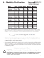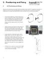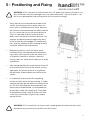
1
MOUNTING INSTRUCTIONS BRUGSANVISNING handilift™ PUMA 40 EN WHEELCHAIR LIFT 90.MI.EN 01062013 9006406B handilift™ Safety Rules WHEELCHAIR LIFT Safety symbols Some precaution are listed in this manual in order to identify potentially dangerous situation in advance and the relevant instructions to avoid them, identified by the following symbols: ! Warning This symbol identifies the presence of instructions which need to be read and followed carefurly in order to avoid potentially dangerous situations. Danger! This symbol identifies the presence of essential information needed to avoid potentially dangerous situations that could cause physical injuries and/or damages to the equipment. To ensure smooth and safe operation, it is necessary to know the exact procedure for the installation and service of the wheelchair lift. WARNING Carefully follow the instructions for the installation and service of the wheelchair lift within this manual. If the instructions within this manual have not been fully understood or further information is required, please contact Handi Mobil immediately. These indications non-fulfilment can cause serious damages, to the equipment and to the vehicles as well as serious injuries to people. ! DANGER Should it be necessary to raise the vehicle being equipped, please check that the characteristics of the lifting device or of the mobile bridge are compatible with the volume and weight of the actual vehicle otherwise there is a risk of serious damage to equipment and vehicles as well as serious injuries to people. 2 handilift™ WHEELCHAIR LIFT ENGLISH © 2011 Handicare All rights reserved. The information provided herein may not be reproduced and/or published in any form, by print, photoprint, microfilm or any other means whatsoever (electronically or mechanically) without the prior written authorization of Handicare. The information provided is based on general data concerning the construction known at the time of the publication of this manual. Handicare executes a policy of continuous improvement and reserves the right to changes and modifi cations. The information provided is valid for the product in its standard version. Handicare can therefore not be held liable for any damage resulting from specifi cations of the product deviating from the standard configuration. Illustrations contained in the manual may deviate from the configuration of your product. The information made available has been prepared with all possible diligence, but Handicare cannot be held liable for any errors contained in the information or the consequences thereof. Handicare accepts no liability for loss resulting from work executed by third parties. Names, trade names, trademarks etc. used by Handicare may not, as per the legislation concerning the protection of trade names, be considered as being available. 3 Index handilift™ WHEELCHAIR LIFT 1 - Preface................................................................................................................................................6 1.1 - Classification and General Indications ...........................................................................................6 1.2 - Fitter Duties/Service........................................................................................................................6 1.3 - Documentations .............................................................................................................................6 1.4 - Warranty .........................................................................................................................................7 2 - General Indications..........................................................................................................................8 2.1 - Technical Description ....................................................................................................... ..............8 2.2 - Models and Installation .................................................................................................. ..............10 2.3 - Technical Specifications ...............................................................................................................10 2.4 - Overall Dimensions ........................................................................................................ ..............11 2.5 - Safety Devices ............................................................................................................... ..............12 2.6 - Signal Stickers Fitting .................................................................................................... ..............13 3 - Preliminary Operations.................................................................................................... ..............15 3.1 - Transport and Movement ............................................................................................... ..............15 3.2 - Package Contents ........................................................................................................................15 4 - Stability Verification........................................................................................................................16 5 - Positioning and Fixing....................................................................................................................18 6 - Electrical Connections....................................................................................................... ..............21 6.1 - Power Supply ...............................................................................................................................21 6.2 - Output Signals ............................................................................................................... ..............21 7 - Presure Socket................................................................................................................. ..............22 8 - Verification........................................................................................................................ ..............23 8.1 - Identification Tag ............................................................................................................ ..............24 8.2 - Equipment Documentations .........................................................................................................25 8.3 - Stickers and Safety Symbols ......................................................................................... ..............26 8.4 - Commands ...................................................................................................................................27 8.5 - Structure and Assembly ................................................................................................. ..............28 8.6 - Hydraulic System ........................................................................................................... ..............29 8.7 - Lift Functions ................................................................................................................................30 8.8 - Electrical System ..........................................................................................................................31 8.9 - Safety Devices ..............................................................................................................................32 8.10 - Loading Test ................................................................................................................. ..............33 4 Index handilift™ WHEELCHAIR LIFT 9 - Chain Regulation...............................................................................................................................6 10 - Optional Kit..................................................................................................................... ..............35 10.1 - Light Kit ........................................................................................................................ ..............35 10.2 - Joystick Control Kit (for “Mobility” model)................................................................... ..............36 10.3 - Joystick Control Kit (for “Commercial” model).............................................................................37 11 - Standard Inspections..................................................................................................... ..............38 11.1 - Lift Function Check....................................................................................................... ..............39 11.2 - Platform Hinge Lubrification Check (only for FP and SP models)...............................................40 11.3 - Tightening of Fixing Screws Check ............................................................................................41 11.4 - Pins and Bushings ......................................................................................................................42 11.5 - Electrical Connections Check ...................................................................................... ..............43 11.6 - Hydraulic Connections Check ....................................................................................................44 11.7 - Tank Oil Level Check .................................................................................................... ..............45 11.8 - Structural Check .........................................................................................................................46 11.9 - Micro Adjustment Check ............................................................................................................47 11.10 - Plate and Stickers Check ........................................................................................... ..............48 12 - Additional Inspections................................................................................................... ..............49 13 - Attachments...................................................................................................................... ..............50 13.1 - “Mobility” Electrical System ......................................................................................... ..............50 13.2 - “Commercial” Electrical System .................................................................................................51 13.4 - Hydraulic System ........................................................................................................................52 5 1 - Preface handilift™ WHEELCHAIR LIFT 1.1 Classification and General Remarks The wheelchair lift “Handi Lift”, manufactured by CAR OIL System S.p.A., which is the object of this instruction manual, is in compliance with the safety requirements of 2006/42/CE directive. The “Handi Lift” wheelchair lift in keeping with the aforementioned directive, is to be considered as a „machine’ and therefore a declaration of conformity has been released, according to annex II of the 2006/42/CE directive . All the necessary instructions for the correct installation of the wheelchair lift are detailed for the installer together with a list of maintenance instructions for servicing procedures. Warning: All installation and service procedures should be carried out in accordance with current health and safety laws. 1.2 Fitter duties/service Fitter/servicer must: • • • • • • • • carry out the installation in accordance to the indications detailed within this manual; carry out the installation by following the indications of the vehicle manufacturer; fill and sign the installation conformity declaration; carry out the verification check procedure for the first commisioning by following the instructions detailed in this manual; register the verification check procedure for the first commisioning in the “use and maintenance” manual; give to the final customer all the required documentation by the rules and regulations in force; carry out the inspections in compliance with the instructions detailed in this manual; register the inspections in the “use and maintenance” manual. 1.3 Documentation The following documents are attached HandiLift™: User manual with installation statement of compliance, verification and inspection. In addition, an original copy of the manufacturer’s declaration of corformity is attached. (Car Oil S.pa). (This manual). Handicare is available for necessary clarification and instruction. 6 1 - Preface handilift™ WHEELCHAIR LIFT 1.4Warranty Handicare guarantees the hydraulic lift for 24 months from the delivery date: the warranty covers for defects concerning material quality and product manufacturing. The warranty does not cover for consumable materials and for defects or failures as a result of: • • Lift installation (on the vehicle) incorrectly carried out or not in compliance with the rules given by the manufacturer. Use and maintenance rules non-compliance Warranty withdraws: The warranty becomes void in case of impacts caused by accidents and/or tampering carried out by a staff who is not part of one of Handicare authorized machines shops. It becomes also void in case of non-fulfillment of the ordinary maintenance instructions reported in the use and maintenance handbook. Handicare refuses all responsibility for damages caused by: • An improper use of the lift. • A failure in following the tables of maximum charge bearing upon the platform (data reported on the metal identification plate). • A failure in carrying out the lift ordinary maintenance. • Interventions or modifications carried out on the lift without Handicare technical office express consent. • A failure in cutting out the electric circuit, by means of vehicle battery isolator system. • Possible removals or tampering on the safety systems located on the hydraulic lift (fuses, safety valves, etc.). • Wrong manoeuvres when moving the hydraulic lift. • Wrong manoeuvres when moving the platform. • Objects or persons situated within the lift range. Warning: Manufacture’s regular inspections dates non-fulfilment will automatically make void the warranty. 7 2 - General Indications handilift™ WHEELCHAIR LIFT 2.1 Technical description The wheelchair lift “Handi Lift” (Fig.1) is installed on the deck of vehicles used for transporting disabled persons in wheelchairs, allowing them to get in/off the vehicle. Lift consists of a base fixed to vehicle loading deck a pair of lifting articulation, installed on the sides of the base, and a loading platform, hinged between the articulations. Deploying/stowing and lifting/lowering movements of the lift are made by means of a parallelogram leverage mechanism driven by a pair of hydraulic cylinders (one for each articulation). The machine is equipped with a hydraulic control unit and an electronic control box which, by means of a remote control, plays the various functional movements; the entire system is electrically powered by the batteries of the vehicle on which it is installed. 8 handilift™ 2 - General Indications WHEELCHAIR LIFT 6 7 4 5 3 8 2 1 Fig. 1 1 External flap 2 Lowering Platform 3 Handrail 4 Lifting articulation 5 Base 6 Hydraulic control unit 7 Hydraulic cylinder 8 Internal flap 9 handilift™ 2 - General Indications WHEELCHAIR LIFT 2.2 Models and installation The wheelchair lift “Handi Lift” is available in three models, which differ from one another in type of loading platform: • FP, has a loading platform that is split horizontally across: the platform extends automatically during the opening phase, and is automatically folded back up when closing, to reduce the overall height of the lift in resting mode and thereby to improve the visibility for the driver while driving. • P, has a perfect loading platform: simply rotate the ramp form the loading position to an upright position when closing. • SP, has a loading ramp which is divided along the length. The two half-platforms rotates in position to form a combined loading platform during the opening phase and separates automatically when closing in order to establish a free passage, which can be used as an emergency exit. The lift is available in a maximum of three sizes and set-ups: • • • Mobility, with provisions for wireless remote control and automatic vehicle door opening; Commercial, without the above-mentioned provisions; Commercial-UK, as the previous one and dedicated particularly to United Kingdom market. 2.3 Technical specifications The main technical specifications of the wheelchair lift Handi Lift ™ is shown below: 10 Power supply voltage: 12 V - 24 V Electric motor power: 0.5 kW Max pressure of the hydraulic system 115 bar; Oil tank capacity: 1,3 lt Max Loading capacity: 360 kg Max lifting height: 0.8 - 1 m Lift total weight: (depending on model) 132 - 160 kg Reserve pump: Yes Hydraulic oil: TEXACO RANDO HDZ 15 Equivalent continuous acoustic pressure (A): <70dB (A) handilift™ 2 - General Indications WHEELCHAIR LIFT 2.4 Overall dimensions The main dimensions of the various versions and settings available for Handi Lift ™: A B C D E F FP84138/L Model 1106 360 1275 1190 840 1380 FP74138/L 1006 360 1175 1190 740 1380 FP70115/L 966 355 1115 1074 700 1150 FP70115C/L 966 355 1115 1074 700 1150 FP84138C/L 1106 360 1275 1233 840 1380 FP74138C/L 1006 360 1175 1233 740 1380 FP84138C-UK/L 1200 360 1275 1370 840 1380 P90138C/L 1106 305 1275 1480 900 1380 P80130C/L 1006 305 1175 1400 800 1300 P76120C/L 966 305 1115 1300 760 1200 SP90138C/L 1106 500 1275 1480 900 1380 SP80130C/L 1006 450 1175 1400 800 1300 SP76120C/L 966 430 1115 1300 760 1200 SP90138C-UK/L 1200 500 1275 1480 900 1380 FP A A E E A D D D E C CB B F C B F P SP A E A A E E A D D D A E D A E D F B CB C B B C BC C B 11 2 - General Indications handilift™ WHEELCHAIR LIFT 2.5 Safety devices Above mentioned controls guarantee good safety standard that can avoid dangerous situations. However, Handicare lifts are equipped with the following additional safety devices: • External flap: to make wheelchair going up/down the platform easier; it is fitted in order to stay in vertical position when platform is far from ground to avoid wheelchair falling risk. • Safety handrails: to provide a firm grip to disable people on wheelchair during lifting/lowering operations. • Internal flap: to make wheelchair going up/down the platform easier; it is fitted in order to stay in vertical position when platform is far from vehicle loading deck to avoid crushing or shearing risk. • Platform safety devices integral with moving members: platform safety devices (handrails, internal and external flaps) are played by lifting arms moving. • Anti – overturning Microswitch: to stop lowering operation if platform rotates respect vertical arms. • Safety Pressure Switch: to stop lift closing operation if platform is still loaded. • Overload protection: Blocks the raising of the lift, if there is more than 125% of the allowed weight on the platform. • Protection from leaks in the hydraulic system: Ensures that the lowering speed of the loading platform does not exceed 50% in the case of loss of hydraylic pressure. • Safety hook: Prevents accidental opening of the platform, in the case of low pressure in the hydraulic system when the lift is closed. • Lift overall dimensions signalling: reflecting strips are fitted on the whole lift perimeter and flashing LED lights are mounted on the front of both vertical lifting arms at the top. 12 11 !! ™ handilift 2 - General Indications 1 2.6 1 WHEELCHAIR LIFT 2 Signal stickers fitting 2 On the front side of left lifting arm On the front side of right lifting arm WARNINGS MANUEL OPERATION OPENING/LOWERING 1) LIFT IMPROPER USE CAN RESULT IN PERSONAL INJURY 2) USER MUST READ AND FOLLOW USE AND MAINTENANCE HAND- 1 11 BOOK OPERATING INSTRUCTIONS 3) CHECK THE LIFT EFFICIENCY AND MAINTENANCE 3 8 7 6 5 4 g 2 22 4) MAKE SURE THE VEHICLE IS FIRMLY BRAKED A 5) DO NOT EXCEED MAXIMUM LOAD ALLOWED (360 KG) B 6) MAKE SURE LIFT RANGE OF ACTION IS FREE FROM ANY OBSTACLE C AND PERSONS !! D 7) DURING LIFT OPERATION STAY AT SAFETY DISTANCE FROM MOVING E USING INSTRUCTIONS 1 7 8 7 7 8 8 6 5 6 6 7 6 4 5 5 3 4 4 5 2 3 3 4 Hvis ikke andet er angivet er alle dimensioner i mm. Materiale S235 2 2 3 2 Udført af Emne Udført af Udført af 8 7 6 5 4 Side 1/1 DS/ISO 2768-1-m 1 1 Tolerance 30-11-2010 Side Tolerance 1/1 Tolerance DS/ISO 2768-1-m S235 DS/ISO 2768-1-m Hvis ikke andet er angivet er alle Side /1 1Side Hvis ikke andet er angivet er alle dimensioner i mm. Vægt Dato 1/1 dimensioner i mm. 30-11-2010 N/A 1 N/A Hvis ikke andet er angivet er alle Materiale Tegningsnummer dimensioner i mm. Materiale S235 Dimension Vægt Tolerance Dato DS/ISO 2768-1-m Vægt Dato 30-11-2010 N/A Materiale S235 Tegningsnummer Dato Tegningsnummer 30-11-2010 Vægt N/A A A A 1) FULLY OPEN DOORS A Udført af Emne Emne Emne A Dimension Tegningsnummer Dimension Dimension B B B B B B 2) TURN ON LIFT ENABLING SWITCH B lift 3 33 A A 1 DEPLOY-DOWN 2 8 F Max kg Max 360 kg Max 360 360OPENING/LOWERING kg A PARTS B AIR LIFT y 3) PUSH AND KEEP PUSHING “DEPLOY-DOWN” BUTTON (A) ON THE C C C C C C C LIFTING/CLOSING C D PUSH BUTTON PANEL UNTIL LIFT IS COMPLETELY OPEN D D D D D 4) PUSH AND KEEP PUSHING “ DEPLOY-DOWN “ BUTTON (A) UNTIL D D E E PLATFORM JOINS THE GROUND E E E E E E 1 11 F F F 7 8 7 7 8 8 8 F LIFTING/CLOSING F 7 5 6 5 5 6 6 6 4 F F 3 4 4 5 2 3 3 4 3 1 2 2 2 F 1 1 1 8 8 3 2 22 1) PUSH AND KEEP PUSHING “STOW-UP” (B) ON THE PUSH BUTTON 8 STOW-UP DEPLOY-DOWN STOW-UP DEPLOY-DOWN DEPLOY-DOWN STOW-UP STOW-UP DEPLOY-DOWN PANEL UNTIL PLATFORM JOINS VEHICLE DECK F F F 2) PRIOR TO CLOSE LIFT>> CHEK PLATFORM TO BE EMPTY > > lift 1 lift 3) PUSH AND KEEP PUSHING lift “STOW-UP” (B) UNTIL LIFT IS COMWHEELCHAIR LIFT PLETELY CLOSED E E by WHEELCHAIR LIFT WHEELCHAIR LIFT WHEELCHAIR LIFT by by by 4) TURN OFF LIFT ENABLING SWITCH E 5) CLOSE VEHICLE DOORS D D B STOW-UP DEPLOY-DOWN A B B 3 3 3 STOP STOW-UP DEPLOY-DOWN 3 33 > > C C START D Handi Lift Handi Lift C B 3 By By 2 2 2 3 4 1 1 1 2 1 5 F F F F QC-INSPECTED START START START START HYDRAULIC LIFT. A A 8 8 A E SERIAL NO E E E CAPACITY 8 HYDRAULIC LIFT. YEAR OF MANUFACTURE SERIAL NO Kg MAX PRESSURE CAPACITY YEAR OF STOW-UP DEPLOY-DOWN STOW-UP DEPLOY-DOWN DEPLOY-DOWN STOW-UP MANUFACTURE STOW-UP DEPLOY-DOWN Kg BAR MAX PRESSURE BAR > > > > OIL SYSTEM s.r.lITALIA - 46029 SUZZARA (MN) ITALIA CAR OIL SYSTEM s.r.l - 46029CAR SUZZARA (MN) Via Pacinotti 14/B - (Z.A.I Rangavino) - Tel. (0376) 536766 Handi Lift ViaD Pacinotti 14/B - (Z.A.I Rangavino) - Tel. (0376) 536766 By Lift Handi r.a. - Fax (0376) 536768 Handi Lift D D By r.a. - Fax (0376) 536768 By D By Identification plate riveted on lift base internal side On internal flap C C C C STOP STOP STOP STOP QC-INSPECTED BY: DATE: BY: STOW-UP DEPLOY-DOWN DATE: STOW-UP DEPLOY-DOWN STOW-UP DEPLOY-DOWN STOW-UP DEPLOY-DOWN handicare.dk handicare.dk > > > > Handi Lift By Lift Handi Handi Lift By By 1 Plate for quality control By 13 1) DREJ LIFT AKTIVERINGSKNAPPEN TIL SLUK 4) LUK BILDØRENE C B B START A 2 - General Indications otaD 0102-11-03 enmE fa trøfdU elairetaM 532S 1 2 3 B 4 5 6 7 Dimension N. DI FABBR. PORTATA Tegningsnummer Udført af PRESS. MAX Side 1/1 er alle Hvis ikke andet er angivet dimensioner i mm. 1 2 3 4 5 6 7 4 5 77 3 WHEELCHAIR LIFT 6 88 66 55 44 6 7 ! 7 8 2 2 2 A A Dimension Dimension 5 6 5 6 5 3 4 3 4 3 4 2 1 S235 DS/ISO2768-1-m Hvisikkeandeterangiveteralle 1Si/de1 dimensionerimm. Udfø 2rt af Dato 30-11-2010 Tolerance 1 Vægt Dato 30-11-2010 N/A Mateerinasile Tolerance D S2im 35 on DS/ISO2768-1-m Hvisikkeandeterangiveteralle 1Si/de1 d iosnneurm im m Tim egenninsg em r. Vægt Dato N/A 30-11-2010 Materiale Tolerance S235 DS/ISO2768-1-m Dvim H isein kskieonandeterangiveteralle 1Si/de1 dimensionerimm. Tegningsnummer 1 2rt af Udfø Tegningsnummer Udført af Dimension Emne Emne A A B B B C C C D D D D E E E BB A D D E E E F F F F 7 8 7 8 7 8 6 5 6 5 6 5 4 3 4 3 4 3 1 2 1 2 1 2 F F D D D B B 6 B C by F 3 3 3 C C C C C 8 4 6 3 5 4 > Handi Lift > By Handi Lift By Handi Lift Dimension Vægt N/A Tegningsnummer Vægt Materiale N/A S235 Dato 30-11-2010 Dato Tolerance 30-11-2010 DS/ISO 2768-1-m Side Tolerance Dato er alle Materiale Vægt Hvis ikke andet er angivet 1/1 DS/ISO 2768-1-m 30-11-2010 S235 N/A dimensioner i mm. Side er alle Tolerance Hvis ikke andet er angivet Materiale 1/1 DS/ISO 2768-1-m dimensioner i mm. S235 1 1 1 3 2 2 2 ! A A A A Tegningsnummer Dimension Tegningsnummer 9 By er alle Hvis ikke andet er angivet dimensioner i mm. Side 1/1 8 6 E E 5 DEPLOY-DOWN 7 STOP DEPLOY-DOWN >DEPLOY-DOWN 6 STOW-UP Dimension Udført af 3 3 3 STOP START STOW-UP 8 By Emne Emne Udført af Emne Udført af 4 4 4 7 STOP START STOW-UP CC DEPLOY-DOWN 7 DEPLOY-DOWN > 8 B B B DEPLOY-DOWN > Handi Lift > By Handi Lift By Handi Lift D D START STOW-UP Tegningsnummer Tegningsnummer 7 B C WHEELCHAIR LIFT STOW-UP Dato Dato 30-11-2010 30-11-2010 7 B C lift STOW-UP Vægt Vægt N/A N/A 8 A lift lift Tolerance Tolerance DS/ISO DS/ISO 2768-1-m 2768-1-m 7 Vægt N/A Materiale 8 Emne A DEPLOY-DOWN Materiale Materiale S235 S235 No parking. To identify wire keyPlaced on both right board connector and left side. E E E DEPLOY-DOWN > WHEELCHAIR LIFT by Hvis ikke Hvisandet ikke andet er angivet er angivet er alleer alle Side Side 1/1 1/1 dimensioner dimensioner i mm.i mm. 8 A 2 2 2 DEPLOY-DOWN > WHEELCHAIR LIFT > by 1 1 LØFTE / LUKKE 1 1 1 Max 360 ! 3 3 3 F F F E 1 1 1 2 2 2 AA 3 3 3 STOW-UP A Tolerance DS/ISO 2768-1-m Materiale S235 BAR A Dato 30-11-2010 Vægt N/A ANNO COSTR. Kg CAR OIL SYSTEM s.r.l - 46029 SUZZARA (MN) ITALIA Via Pacinotti 14/B - (Z.A.I Rangavino) - Tel. (0376) 536766 r.a. - Fax (0376) 536768 UDFOLDE / SÆNKE !! ! STOW-UP By Emne SOLLEVATORE IDRAULICO MOD. MANUEL BETJENING STOW-UP Handi Lift D !! ! 2 1 1 1 4 4 4 DEPLOY-DOWN > > By 8 Max 360 kg Max Max 360 360 kg kg STOP STOW-UP DEPLOY-DOWN 8 Handi Lift !! ! 1 1 1 A STOW-UP ella re tevigna re tedna ekki sivH .mm i renoisnemid B handilift™ B A tgæV A/N ecnareloT m-1-8672 OSI/SD ediS 1/1 noisnemiD remmunsgningeT Max 360 kg F F 1 Hvis ikke andet er angivet er alle dimensioner i mm. Side 1/1 Tolerance DS/ISO 2768-1-m Materiale S235 Dato 30-11-2010 Vægt N/A A DD Dimension B B C FF 11 D C EE 8A STOW-UP DEPLOY-DOWN F Hedges. > lift E WHEELCHAIR LIFT 88 by 6 7 8 7 6 5 A 4 3 66 2 1 Hvis ikke andet er angivet er alle dimensioner i mm. Dato 30-11-2010 Vægt N/A Tegningsnummer Dimension A B E C D E 4 F2 3 1 Hvis ikke andet er angivet er alle dimensioner i mm. Dato 30-11-2010 Vægt N/A Tegningsnummer Dimension Emne 8 E Side 1/1 Tolerance DS/ISO 2768-1-m Materiale S235 Udført af 44 B C D 5 55 F F 8 A 7 6 5 4 3 2 1 D 6 Side 1/1 Tolerance DS/ISO 2768-1-m Materiale S235 Udført af Emne Max 360 kg 8 DD 7 8 A 77 5 8 FF 4 D E F 3 1 2 2 enmE fa trøfdU EE 30A 7 3 ! 6 4 5 F 3 4 5 6 7 16A 4 E 8A Tegningsnummer 11 8 3 2 88 10 10 2 Udført af 77 9 Emne 66 3 55 1 1 44 4 Manual valve black plastic pin Manual pump slot 33 7 6 5 B D 4 3 ULICO MOD. CC B ANNO COSTR. C BAR C s.r.l - 46029 SUZZARA (MN) ITALIA Warning: Z.A.I Rangavino) - Tel. (0376) 536766 - Fax (0376) 536768 In the case of loss or excessive wear, identification tags and safety stickers should be rapidly replaced. Please contact an authorized Handicare centre for details C 77 88 8 7 B F F AA 6 5 F enmE 4 3 2 1 fa trøfdU 1 2 3 4 5 6 1 22 To identify optional functions connectors 33 44 55 66 E FF 14 BB D B 7 PRESS. MAX C Kg 3 - Prelimiary operations handilift™ WHEELCHAIR LIFT 3.1 Transport and movement For transportation, the lift must be secured to a pallet and packed with sheets of protective plastic and cardboard. For transportation purposes, a fork lift truck or a hoist is advised. All packing materials are ecological and recyclable. The packing materials should be disposed off correctly. The local council or refuse department will be able to offer advice regarding disposal requirements. ! 3.2 DANGER: Cardboard and protective plastic sheets used for packing purposes can cause suffocation. Package contents The size of the wheelchair lift package “Handi Lift” is 135x42 cm. The height of the wheelchair lift package varies according to the model type. 140 cm for the FP model; 170 cm for the P and SP models. The package weight is 13 kg. WARNING: During the unpacking process be very careful to not damage the contents. WARNING: Before beginning any installation procedure of the wheelchair lift, you should: • • • • verify if there are any specifications from the vehicle manufacturers to respect; remove from the vehicle any unnecessary object that could impede the installation procedure of the lift (spare wheel, accessories etc); disconnect the electrical supply from the battery; disconnect any electronic control units from the vehicle as specified by the manufacturer. 15 handilift™ 4 - Stability Verification WHEELCHAIR LIFT 4 Stability Verification Before starting to position and fix the lift, as described in Chapter 5, it is necessary to verify the stability of the vehicle with the lift installed open and maximun overhang. Here are the instructions for this verification procedure: • Obtain from the vehicle registration documents, the information required for stage (P) and the rear overhang limits (S) and write them in Section A of Chapter 1 of “use and maintenance” manual (“Log verification for the first commissioning”); • From the vehicle obtain measurement (A) from the loading base to the height of the bumpers (Fig.2) and compare it to the values as detailed in the table below, obtain measurement (B) from the distance of the external edge of the lift base to the external edge of the bumpers; the values of B as detailed in the table are valid for all models of lift apart from FP70115, FP70115C, P76120C and SP76120C. The values for these 2 models are detailed as B* in the table; transcribe the values obtained of A, B, B* in Section A of Chapter 1 of “use and maintenance” manual (“Log verification for the first commissioning”); Fig. 2 A (mm) 0 20 40 60 80 100 120 140 160 B (mm) 210 230 245 265 280 295 305 320 330 C (mm) 230 250 270 290 300 315 315 315 315 Fig. 3 • 16 According to the model of “Handi Lift” to be installed, obtain the relevant d1, G1, d2, G2 values and the weight (M) of the lift, from the following table and transcribe them in Section A of Chapter 1 of “use and maintenance” manual (“Log verification for the first commissioning”); 4 - Stability Verification handilift™ WHEELCHAIR LIFT Model d1(m) G1(daN) 2d(m) G2 (daN) M(daN) FP84138 0,10 90 1,12 70 160 FP84138C 0,10 90 1,12 70 160 FP84138C -UK 0,10 90 1,12 70 160 FP74138 0,11 88 1,12 62 150 FP74138C 0,11 88 1,12 62 150 FP74138C-UK 0,11 88 1,12 62 150 FP70115 0,95 80 1,00 52 132 FP70115C 0,95 80 1,00 52 132 P90138C 0,10 90 1,12 57 147 P80130C 0,11 88 1,12 49 137 P76120C 0,95 80 1,00 45 125 SP90138C 0,10 90 1,12 70 160 SP90138C-UK 0,10 90 1,12 70 160 SP80130C 0,11 88 1,12 62 150 SP76120C 0,95 80 1,00 52 132 • By entering the values previously obtained into the following formula you will be able to obtain the minimal reaction (R min) for the anterior axle of the vehicle and transcribe it in Section A of Chapter 1 of “use and maintenance” manual (“Log verification for the first commissioning”); • Obtain from the vehicle registration documents, the value of the ultimate load capacity for the anterior axle (R) and transcribe it in Section A of Chapter 1 of “use and maintenance” manual (“Log verification for the first commissioning”); • If the value of R is higher than the value of R min, the stability of the vehicle is verified; complete Section A of Chapter 1 of “use and maintenance” manual (“Log verification for the first commissioning”), with signature and stamp and proceed with the lift installation procedure as described in the following chapter. Stability check is positive when R < R min WARNING: Please follow the instructions in this manual carefully when carrying out the stability verification of the “Handi Lift” wheel chair lift. If the instructions in this manual have not been properly understood or if further information is required, please contact Handicare immediately. Serious damage to vehicles and human injury could be caused if these instructions are not carefully fulfilled. 17 5 - Positioning and Fixing handilift™ WHEELCHAIR LIFT 5 Lift Positioning and Fixing Here are all the necessary instructions for the installation of the “Handi Lift” wheelchair lift for the vast majority of vehicles on sale. Not being able to cover all possible cases, we advise you to contact Handicare for any further information.Here are the instructions for this verification procedure: • Pressurize the hydraulic system of the lift by using its hand pump as follow: screw the provided lever in its proper place in the hydraulic control unit (Fig.4) and put the hand pump into action with an alternate vertical movement until the pumps resistance blocks the lift in the “closed” position. • Open the door(s) of the vehicle, where the lift will be placed, and block them on the “open” position”. Measure the height and the width of the compartment and verify that they are bigger than the overall dimensions of the lift (Fig.6). • Using a forklift or an equivalent means with a bigger capacity than the total weight of the lift (see technical specifications), place it at the same height as the surface of the vehicle (placing compartment). Push the lift inside the vehicle in a central position in respect to the volume of the compartment. Align the external edge at the base of the lift parallel to the closing edge of the door(s). • Fig. 4 Fig. 5 Fig. 6 Position the lift in order to its base external edge is at distance “B” (calculated in Chapter 4) from vehicle bumper external edge. Fig. 7 18 5 - Positioning and Fixing handilift™ WHEELCHAIR LIFT WARNING: If lift is placed at a distance lower then “B” quote (calculated in Chapter 4) stability verification must be made again and “use and maintenance” manual Chapter 1, section A must be updated (“Log verification for the first commissioning”). • Verify, both on the inside and the outside of the vehicle, that the doors of the vehicle close correctly, with no interference from the lift. Measure the minimum distance between the doors and the lift; if it is more than 40 mm (minimum distance) (Fig.7) it is possible to draw up the lift to the doors until it reaches the minimum distance. Pay attention to keep the external edge at the base of the lift and the closing edge in a parallel position. Also pay attention to the centering of the lift inside the width of the compartment. • Before fixing the lift, check that there are no interferences (in correspondence to the tightening screws) with the parts under the frame, such as hydraulic conduits or wireways, electrical wiring, cables etc. Move the lift sideways to avoid interference. • After having identified the exact position of the lift on the fitting surface area of the vehicle, use the eight holes at the base of the lift as a guide for the drilll holes to be made on the surface of the vehicle. • It is important to ensure that the supporting surface to which the lift will be fastened, is stable and that the holes do not affect the stability of the lift. The lift is provided with fastening plates and these have to be positioned, in correspondence to the holes, under the frame (Fig.8). They need to be tightened using n°8 M10 screws with their screw nuts and washers (Fig.9) using a torque equalto 50 Nm. Fig. 8 Fig. 9 WARNING: If it is essential to use screws with a length greater than those of the screws provided, make sure that they are M10 class 8.8 screws. 19 5 - Positioning and Fixing handilift™ WHEELCHAIR LIFT WARNING: Most vehicles on sale have a corrugated structure (Fig.10) and in these cases the empty spaces need to be filled with plates which act as spacers in the bolt fixing area. Fig. 10 WARNING: If, in order to stiffen the area that will support the lift, welding is needed, first unplug all the existing electrical connections on the vehicle and follow the manufacturer’s instructions with care. WARNING: It is the responsibility of the installer to verify the adequate resistance and crush proof characteristics of the surface of the vehicle to which the lift will be attached. Handicare declines all responsibility for any damage caused by such instructions and verifications non-stilfilment and it will automatically consider void the warranty of the lift. 20 6 - Electrical connections handilift™ WHEELCHAIR LIFT 6.1 Power Supply After a correct positioning and fastening of the lift to the loading deck of the vehicle, connect the eyelet connectors of the 16 mm2 wires to the battery of the vehicle, in particular, connect the red wire to the positive pole and the black wire to the negative pole. WARNING: Considering the 12 V or 24 V application, connect the earth wires directly to the negative pole of the battery. WARNING: If wires need to go through walls or panels use specific rubber gromits to avoid damaging sheaths and wires. WARNING: Connecting procedures must comply with the instructions given out by the vehicle manufacturers. Handicare declines all responsibility for any damage caused by electric connections not in compliance with what has been stated in this manual and with the technical specifications of the vehicle manufactures. 6.2 Output Signals The lift is provided with a six pins female connector for signal wires not connected; in this situation the lift is not enabled to function. Before installation, if any verifications of the lift are necessary, connect to the power supply and connect the six-way female connector to its correspondent male connector which is placed inside the hydraulic control unit. During installation, remove the bridge on the female connector and perform the connections as shown in Fig.11, installing a warning light inside the cabin, a beeper and a system enabling switch; connect the female connector to its male connector positioned inside the hydraulic control unit. Fig. 11 Handicare decline all responsibility for damage caused by non fulfiment of these instructions and automatically deem the warranty to be void in such cases. 21 7 - Pressure Socket handilift™ WHEELCHAIR LIFT 7 Pressure Socket WARNING: These instructions are for the exclusive use of appropriately trained technical personnel. ! DANGER: Before using the pressure regulator make sure that platform is firmly on the ground in order to eliminate the pressure set at zero from hydraulic system pressure. Inside the hydraulic control unit there is a pressure socket. To measure the pressure in the hydraulic circuit, unscrew the N°5 fixing screws on the lid of the control unit and remove it; use an Allen wrench 6 to screw off the lid of the pressure regulator placed on the T-piece found on the top of the distribution block of the control unit, in correspondence to the pressure regulator and connect through the male connector ¼” WARNING: After disconnecting from the pressure socket, make sure to screw and tighten the lid. 22 8 - Verification handilift™ WHEELCHAIR LIFT Verification for first commissioning The following instructions are necessary for the first commissioning of the “Handi Lift” wheelchair lift after it has been installed on the vehicle. Note that every record is equipped with a description of the verification check, time estimations, number of personnel required and necessary materials and equipment. After each verification has been carried out, complete, sign and stamp Section B of Chapter 1 of “use and maintenance” manual (“Log verification for the first commissioning”). WARNING: These instructions are for the exclusive use of appropriately trained technical personnel. WARNING: For the verification check of first commissioning of the “Handi Lift” wheelchair lift the instructions detailed in this manual must be carefully fulfilled. If the instructions in this manual have not been properly understood or if further information is required, please contact Handicare immediately. Serious damage to vehicles and human injury could be caused if these instructions are not fulfilled. Handicare declines all responsibility if the verification check for the first commissioning is not followed properly and if the appropriate records are not compiled correctly (in Section B of Chapter 1 of “use and maintenace” manual) and will automatically consider the warranty void. 23 handilift™ 8 - Verification WHEELCHAIR LIFT 8.1 Identification tag Verification Time required 5 Personnel required 1 Equipment None Materials None Description Visibly verify the presence of the aluminum identification tag on the base of the installed lift. Check the integrity of the fixing rivets and the tag legibility. NOTE: 24 8 - Verification handilift™ WHEELCHAIR LIFT 8.2 Equipment documentation Verification Time required 5 Personnel required 1 Equipment None Materials None Description Check that you have received the use and maintenance manual that should be compiled prior to delivery. Check that you have received the manufacturer’s declaration of conformity. Check that you have compiled and signed the declaration of conformity of the installation. NOTE: Confirm that the user has received all the documentation described in Chapter 1.3. 25 8 - Verification handilift™ WHEELCHAIR LIFT 8.3 Stickers and safety symbols Verification Time required 10 Personnel required 1 Equipment None Materials None Description Check that there are reflector strips on both sides of the platform. Check for the presence of and the legibility of all safety stickers described in Chapter 2.6 of this manual. Check that the cabin light is in full working order as well as the buzzer light and the intermittent led lights (if present). NOTE: Here is a description of the correct functioning of the safety warnings of the lift: • • • 26 The cabin light should be off when the lift is closed and the system disengaged otherwise it should be on at all times. Buzzer should only function when a button is pressed on the enabling system. The intermittent led lights (if present) should only function when the lift is open. This applies to both enabling systems and not. handilift™ 8 - Verification WHEELCHAIR LIFT 8.4Commands Verification Time required 5 Personnel required 1 Equipment None Materials None Description Check the presence of the wired remote control, of the wireless remote control (optional), the Joystick command kit (optional) and the manual emergency commands (return command key valve for „down” and the hand pump lever). NOTE 27 8 - Verification handilift™ WHEELCHAIR LIFT 8.5 Structure and assembly Verification Time required 10 Personnel required 1 Equipment Key gauge Materials None Description Check the correct tightening of the fixing screws on the vehicle lift. Visibly check the integrity of the soldering and check that there are no damaged parts to the structural components of the lift. NOTE: The required tightening torque to use for n°8 fixing screws from the lift to the vehicle is equal to 50Nm. 28 8 - Verification handilift™ WHEELCHAIR LIFT 8.6 Hydraulic System Verification Time required 10 Personnel required 1 Equipment Tool kit Materials None Description Check that the oil in the tank is at the correct level; check for seepage / leaking from the hydraulic system and for leaks from the hydraulic cylinder. Check the integrity of the hydraulic tubes. NOTE: To check the oil level when the lift is closed, remove the cover of the hydraulic control unit and check that the oil level in the tank is above the „MIN” mark and under the „MAX” mark. 29 8 - Verification handilift™ WHEELCHAIR LIFT 8.7 Lift functions Verification Time required 10 Personnel required 1 Equipment None Materials None Description Check that at the end of the deploying phase and at the end of the lifting movement platform is at the some of vehicle deck. Check that the lift has been closed correctly. Check that the internal lift flap joins the platform at the base of the vehicle when the platform is at vehicle deck level and that it stays vertical during the up and down phases. Check that the external flap joins the platform when the lift is on the ground and that it stays vertical during the up and down phases. NOTE: If on of the checks is negative, adjust micro camshafts as described in Chapter 11.9 “Micro regulation check”. 30 handilift™ 8 - Verification WHEELCHAIR LIFT 8.8 Electrical System Verification Time required 10 Personnel required 1 Equipment Tester Materials None Description Verify the working order of the system enabling switch and confirm the exact electrical connections of the lift to the battery of the vehicle checking if this is charged. Check that the automatic door opening mechanism (if present) operates properly. NOTE: 31 handilift™ 8 - Verification WHEELCHAIR LIFT 8.9 Safety Devices Verification Time required 10 Personnel required 1 Equipment None Materials Object and a weight of 15kg Description Check the correct functioning of the safety hook by testing with the down key valve a slight release of pressure from the hydraulic system when the lift is closed. Check the working order of the anti -tilt mechanism by lowering the platform onto an object positioned on the ground. Check the working order of the safety pressure plug by closing the lift after having positioned 15 kg onto the platform at loading level. NOTE: If check is negative contact Handicare 32 8 - Verification handilift™ WHEELCHAIR LIFT 8.10 Loading test Verification Time required 30 Personnel required 1 Equipment Lifting devices (fork lift or hoist) with proper load capability Materials 450kg payload, 360kg payload, rule, goniometer (0,5° precision) Description Carry out the static deformation and derivative tests as well as the dynamic test with the relative verifications. Check the working order of the safety overload system by applying a 450 kg load on the platform while it is on the ground, press the „up‟ command button and verify that the range is clear. NOTE: To carry out the static deformation test, follow the instructions below: • Position the platform at the halfway point between the ground and the loading area of the vehicle. • Measure the height of the platform and its angular alignment in relation to the loading area of the vehicle. • Apply a load of 450 kg onto the platform and then remove it. • Repeat the height and angular measurements of the platform and check that there are no permanent deformations either to the lift or the vehicle fixings which could be a detriment to the correct functioning of the lift. To carry out the static derivation test, follow the instructions below: • Position the platform at the loading area level of the vehicle. • Apply a load of 450 kg onto the platform. • Measure the height of the platform and its angular alignment in relation to the loading area of the vehicle. • Repeat the measurements after a trial period of 15 minutes. Check that the vertical derivation of the platform between the two measurements is not greater than 15 mm and that the angular derivation is not greater than 2°. To carry out the dynamic test, follow the instructions below: • Position the platform at ground level. • Apply a load of 360 kg onto the platform. • Check the complete functioning of the lift‟s up and down movements when fully loaded. See Annex II of EN 1756 rule. If check is negative contact Handicare 33 9 - Chain Regulation handilift™ WHEELCHAIR LIFT 9.1 Chain Regulations The following instructions apply only to the lift model FP. If the external flap fail to open correctly when the platform reaches ground level, adjust the chain on both sides by adhering to the following instructions: • • • Position the lift at the vehicle deck level. Dismantle the end-stop on the side of the platform by removing the n°2 screws (Fig.12). Dismantle the side cover to the front of the platform by removing the n°4 screws (Fig.13). Fig. 12 • • • Loosen the chain by turning only once the n°2 regulatory nuts (Fig.14). Unscrew the grub screw dowel to regulate the inclination level of the platform (Fig.15), until the two semi platforms are realigned. Check that the external flap opens correctly onto the ground. If satisfactory, reassemble all the components, otherwise, follow the instructions again from the beginning. Fig. 14 34 Fig. 13 Fig. 15 10 - Optional Kit handilift™ WHEELCHAIR LIFT 10.1 Light Kit The Light kit is composed of n°2 lintermittant led lights, n°4 tapping screws and n°2 electrical connectors. To install the Light kit follow the instructions (on each side of the lift). • • • • Thread the led light power cord into the hole (Fig.16). Fix the led lights to lift by means of the n°2 tapping screws (Fig. 17). Thread the contacts of the light power cord into the connector in the light pack (Fig.18). Connect the lights to the branch of electrical system, which is identified with the label, „lights”. (Fig.19). Fig. 17 Fig. 16 Fig. 18 Fig. 19 35 10 - Kit Optional handilift™ WHEELCHAIR LIFT 10.2 Joystick control kit (for “Mobility” model) Joystick control kit is composed of n°1 wired joystick and cap, n°1 cable conduit, n°1 4 pins connector and n°1 sticker. To install the Joystick control kit on Handi Lift (Mobility model), follow the instructions below: • • • Remove the cap from the left side hand rail. Fit the cable conduit as shown in Fig.20. Feed the cable into the handrail and feed through, without re positioning the cap as shown in Fig.20-21 and feed it into the conduit. • Fit the 4 pins connector (from the pack) to the free end of the cable and connect it to the branch of the lifts electrical system identified with the label „Interr”. Test the switch and rotate the cap until the command position for „up” is towards the top. Apply the cap and the sticker (Fig.22-23). Fig. 20 • • Fig. 22 36 Fig. 21 Fig. 23 10 - Kit Optional handilift™ WHEELCHAIR LIFT 10.3 Joystick control kit (for “Commercial” model) The Joystick control kit is composed of n°1 wired Joystick divided into 3 parts and with cap, n°1 cable conduit 250 mm in length, n°1 cable gland and conduit 600 mm in length, n°1 4 pins male connector and n°1 4 pins female connector, n°4 female Faston connectors , n°4 male Faston connectors and n°1 sticker. To install the Joystick control kit on the Handi Lift (Commercial model), follow the instructions below: • • • • • • • • • Remove the cap from the left side hand rail. Fit the 250 mm conduit inside the left vertical arm and the 600 mm conduit inside the lower left horizontal arm. Feed the Joystick side cable through the hand rail, without re positioning the cap, feed the cable as shown in Fig.20-21 inserting into the 250 mm conduit. Feed the central cable into the 600 mm conduit. Feed the free end under the base until it reaches the control unit. Connect the electrics as detailed in diagram (Fig.24). Test the switch and rotate the cap until the command position for „up‟ is towards the top. Apply the cap and the sticker (Fig.22-23). Check for the correct positioning of the cable when the lift is in operation. Fig. 24 37 11 - Inspections handilift™ WHEELCHAIR LIFT Standard inspections Standard inspections should be carried out annually by Handicare Authoriced Service Centre. They allow for greater operational safety and guarantee a longer lifetime for the Handi Lift wheelchair lift. Here are the instructions for standard lift inspections to be followed by service centre. In particular, in every inspection form you can find a description of the verification carried out, and of the possible intervention in case of a negative check test result, time estimations, number of personnel required and necessary materials and equipment. The record for the standard inspection, present “use and maintenance” manual, must be filled, stamped and signed after every test check. WARNING: These instructions are for the exclusive use of appropriately trained technical personnel. WARNING: In the standard inspection phase, the servicer is also required to carry out any maintenance interventions even if they are the responsibility of the user of the lift, and as described in Chapter.7. WARNING: After 2000 HOURS of functioning and always after 10 YEARS, the lift should undergo a full and complete service at a Handicare authorized centre, who will subsequently issue a new user manual with new inspection procedures prior to resuming service. If this is not the case the lift must not be operated. WARNING: For the standard inspections on behalf of the servicer of the Handi Lift wheelchair lift the instructions detailed in this manual must be carefully adhered to. If the instructions in this manual have not been properly understood or if further information is required, please contact Handicare immediately. Serious damage to vehicles and human injury could be caused if these instructions are not adhered to. Handicare decline all responsibility for damage caused due to incorrect maintenance or lack of maintenance of the lift and automatically deem the warranty to be void in such cases. 38 handilift™ 11 - Inspections WHEELCHAIR LIFT 11.1 Lift function test Time required Verification Intervention 10 To be defined Personnel required 1 To be defined Equipment None To be defined Materials None To be defined Description Carry out n°2 complete cycles of deploying, lowering, lifting and stowing and check the correct functioning of the lift. According to the type of malfunction present, operate as detailed in the reference records or contact Handicare. NOTE: 39 handilift™ 11 - Inspections WHEELCHAIR LIFT 11.2 Platform hinge lubrification check (only for FP and SP models) Time required Verification Intervention 10 10 Personnel required 1 1 Equipment None Greaser Materials None Grease IP ATHESIA EP GR 2 Description Visibly check the lubrification of the double hinges of the loading platform. Grease the hinges using the suggested product or an alternative grease. NOTE: Tighten the screws by a means of the key gauge uing a torque equal to 50 Nm. 40 handilift™ 11 - Inspections WHEELCHAIR LIFT 11.3 Tightening of fixing screws check Time required Verification Intervention 5 5 Personnel required 1 1 Equipment Key gauge Key gauge Materials None None Description Check that the torque of the n°8 tightening screws on the base of the lift is 50 Nm. Tighten the screws by a means of the key gauge uing a torque equal to 50 Nm. NOTE: 41 handilift™ 11 - Inspections WHEELCHAIR LIFT 11.4 Pins and bushings Verification Intervention Time required 15 120 Personnel required 1 1 Equipment None Hold and tool kit Materials None Spare parts Description Carry out n°2 complete cycles of deploying, lowering, lifting and stowing and visibly check there are no between pins and bushings of the articulations. Remove the lift from the vehicle deck (carefully follow the instructions in Chapter 5) and substitute the bushings. NOTE: 42 handilift™ 11 - Inspections WHEELCHAIR LIFT 11.5 Electrical connections check Time required Verification Intervention 30 30 Personnel required 1 1 Equipment Tester Electrician’s equipment Materials None Spare parts Description Visibly check the state of the wirings and check the working order of the micro-switches and connectors. Substitute any damaged parts with spare parts. NOTE: 43 handilift™ 11 - Inspections WHEELCHAIR LIFT 11.6 Hydraulic connections check Verification Intervention Time required 5 20 Personnel required 1 1 Equipment None Hydraulic equipment Materials None Spare parts Description Visibly check the state of the pipes Substitute any damaged parts with and of the hydraulic connections spare parts. and check for seepages and leaks. NOTE: 44 handilift™ 11 - Inspections WHEELCHAIR LIFT 11.7 Tank oil level check Verification Intervention Time required 5 10 Personnel required 1 1 Equipment None Hydraulic equipment Materials None Oil TEXACO RANDO HDZ 15 Description With the lift closed remove the cover of the hydraulic control box and check that the level of oil in the tank is above the mark, „MIN”. Remove the distributor block cap from the hydraulic control unit and fill the tank with the suggested product, or an acceptable alternative. Do not fill the tank with oil above the mark, „MAX”. NOTE: 45 handilift™ 11 - Inspections WHEELCHAIR LIFT 11.8 Structural check Verification Intervention Time required 30 To be defined Personnel required 1 2 Equipment None Hoist and tool kit Materials None Spare parts Description Visibly check the integrity of the structural elements for signs of permanent damage, fissures or rusting and there are no bucklings, fissure or rusting. Remove the lift from vehicle deck (carefully follow the instructions in Chapter 5) and substitute the damaged components with spare parts. NOTE: 46 handilift™ 11 - Inspections WHEELCHAIR LIFT 11.9 Check micro adjustment Verification Intervention Time required 10 20 Personnel required 1 1 Equipment None Tool kit Materials None None Description Carry out n° 2 complete cycles of deploying, lowering, lifting and stowing and visibly check the correct positioning of the loading platform at vehicle deck level +, the correct closure of the lift and the correct functioning of the anti-tilt mechanism in the lowering movement phase. Adjust M2 micro (anti-tilt device) control rod and the camshafts of M1 and M3 micros as detailed in the note below by loosering the relevant fixing screws and finally tightening them again in order to lock rod or camshaftsin the proper position. NOTE: Find following “Handi Lift” operation system described in consideration of micros M1, M2 ed M3 positions: • In the closed position micro M1 and M2 are open and the micro M3 is closed. • In open position the lift stops at the loading platform when micro M1 closes the circuit. • During lowering phase anti-tilt security lock is enable if micro M2 opens the circuit. • During lifting phase platform stops at vehicle deck level when micro M3 opens the circuit. • During stowing the safety pressure plug of the loaded platform is excluded and the electric pump cut out timer is enabled when micro M3 closes the circuit. 47 handilift™ 11 - Inspections WHEELCHAIR LIFT 11.10 Plate and stickers check Verification Intervention Time required 10 10 Personnel required 1 1 Equipment None Rivetter Materials None Spare parts Description Visibly check the integrity of the aluminium identification plate as well as the other safety stickers described in Chapter 2 of this manual. Replace the identification plate and any wearing out or missing stickers with spare parts. NOTE: 48 12 - Additional Inspections handilift™ WHEELCHAIR LIFT 12 Additional inspections The authorized Handicare, service centre which has been contacted by a customer encountering anomalies or malfunctioning of the wheelchair lift, must carry out the required checks and if necessary operates in order to solve the associated problems. At the end of the additional inspection service centre must fill, stamp and sign the relevant form in lift “use and maintenance” manual. WARNING: In the additional inspection phase, the service centre is also required to carry out any maintenance interventions even if they are the responsibility of the user of the lift, and as described in Chap. 7. WARNING: For the additional inspections on behalf of the servicer of the Handi Lift wheelchair lift the instructions detailed in this manual must be carefully adhered to. If the instructions in this manual have not been properly understood or if further information is required, please contact Handicare immediately. Serious damage to vehicles and human injury could be caused if these instructions are not adhered to. Handicare decline all responsibility for damage caused due to incorrect maintenance or lack of maintenance of the lift and automatically deem the warranty to be void in such cases. 49 handilift™ 13 - Attachments WHEELCHAIR LIFT 13.1 50 “Mobility” electrical system DO: open door PR: pressure switch TL: teleruptor EP: electric pump VE: vehicle EV: electric valve BT: battery CN: connector handilift™ 13 - Attachments WHEELCHAIR LIFT 13.2 “Commercial” electrical system PR: pressure switch TL: teleruptor EP: electric pump VE: vehicle EV: electric valve BT: battery CN: connector 51 handilift™ 13 - Attachments 13.3 WHEELCHAIR LIFT Hydraulic system CS: hydraulic cylinder HB: hose burst valve PP: pressure plug SCR: adjustable throttle EV: electric valve M: electric motor PR: pressure switch SI: tank F: suction filter P: hydraulic pump S: check valve T: cap SC: throttle GEP: electric pump VM: max pressure valve PM: manual pump 52 handilift™ NOTES ___________________ ___________________ ___________________ ___________________ ___________________ ___________________ ___________________ ___________________ ___________________ ___________________ ___________________ ___________________ ___________________ ___________________ ___________________ WHEELCHAIR LIFT 53 handilift™ NOTES ___________________ ___________________ ___________________ ___________________ ___________________ ___________________ ___________________ ___________________ ___________________ ___________________ ___________________ ___________________ ___________________ ___________________ ___________________ WHEELCHAIR LIFT 54 handilift™ NOTES ___________________ ___________________ ___________________ ___________________ ___________________ ___________________ ___________________ ___________________ ___________________ ___________________ ___________________ ___________________ ___________________ ___________________ ___________________ WHEELCHAIR LIFT 55 Baggeskærvej 48 DK-7400 Herning T +45 97 12 96 22 [email protected] handicare.dk