1
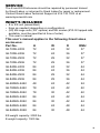
E and ES Series Enclosures
Installation Instructions
WeRackYourWorld.com
1-866-TRY-GLCC (879-4522)
Instructions for the following Great Lakes Enclosures:
GL720E-2432, GL720E-2436, GL720E-2932, GL720E-2936, GL840E-2432,
GL840E-2436, GL840E-2932, GL840E-2936, GL480ES-2442, GL780ES-2442,
GL780ES-3042, GL840ES-2442, GL840ES-3042, GL840ES-2448, GL840ES-3048
Preface
This manual is provided to prevent service personnel from committing
an act that results in the risk of fire, electric shock, or injury to persons.
Only trained service personnel should receive, unpack, and assemble
the E and ES Enclosures. In addition, only trained service personnel
should install equipment in enclosures.
Safety Symbols Used in this Manual
This manual provides general safety guidelines to be observed during
installation, operation, and maintenance of the E and ES Enclosure.
WARNING: Failure to follow directions in the warning could result in
injury to persons or loss of life.
CAUTION: Failure to follow directions in the caution could result in
damage to equipment or storage data.
Safety Considerations
WARNING: Improper handling and use of the E and ES Enclosure could
result in equipment damage, serious injury, or possible death.
Only trained service personnel should be used to remove the enclosure
from the pallet. Also, be sure you have a sufficient number of service
personnel. Do not attempt to move enclosures by yourself.
Only UL® Listed ITE (Information Technology Equipment) units should
be installed inside the E and ES Enclosure.
Be sure to read and follow all individual manufacturer equipment
manuals for safety and installation instructions.
Proper spacing is required when installing electrical equipment to avoid
electrical shock. Maintain minimum spacing between the accessories
and components and the computer enclosure assembly for safe
operation of the equipment when installed in accordance with the
National Electric Code ANSI/NFPA 70-1999.
The ambient temperature operating range for the E and ES Enclosure
and accessories is +50 to +95° F (+10 to +35° C).
The non-operating temperature is -4 to +140° F (-20 to +60° C).
2
Service
The E and ES Enclosures should be repaired by personnel trained
by Great Lakes, or returned to Great Lakes for repair or replacement.
Contact Great Lakes Technical Support at 814.734.7303 or at
werackyourworld.com
What’s Included
• E or ES unit (assembled)
• Keys as needed (depending on configuration)
• (50) M6 cage nuts (3/8" square) and M6 screws (#10-32 tapped rails available, must be specified at time of order)
• This user’s manual
This user’s manual applies to the following Great Lakes
enclosures:
WDRMU
Part No.H
GL720E-2432
72 243237
72
GL720E-2436
243637
GL720E-2932
72
293237
72
GL720E-2936
293637
GL840E-2432
84
243244
GL840E-2436
84
243644
84
GL840E-2932
293244
84
GL840E-2936
293644
48
GL480ES-2442
244224
78
GL780ES-2442
244242
78
GL780ES-3042
304242
84
GL840ES-2442
244244
84
GL840ES-3042
304244
84
GL840ES-2448
244844
84
GL840ES-3048
304844
ES weight capacity: 2000 lbs.
E weight capacity: 1500 lbs.
3
Installation
Receiving, Unpacking, and Removing the E or ES Enclosure
from the Pallet
Inspect and report any damage before receiving. Unpack the enclosure
by carefully removing the corrugated carton and corners. Avoid
damaging the enclosure when removing packaging.
WARNING: Only trained service personnel should be used to remove
the enclosure from the pallet. Also, be sure you have a sufficient
number of service personnel. Do not attempt to move enclosures
by yourself.
WARNING: Be careful when moving enclosures before installation.
Sudden stops and starts, excessive force, obstructed routes, and
uneven floor surfaces may cause the enclosure to topple over.
Loading Equipment
WARNING: Only install equipment after the E and ES Enclosure has
been properly secured. Do not move the E and ES Enclosure assembly
while loaded.
Once in place at the desired/intended location, deploy the leveling feet
for maximum stability.
Rated or maximum load capacity for the E and ES Enclosure is 1500
and 2000 pounds, respectively, on the floor or on leveling glides.
To maintain a uniform distribution of the mechanical load in the E and
ES Enclosure, load the heaviest equipment first, at the bottom of the
E and ES Enclosure and load the lighter units at the top.
4
OPERATING DOOR HANDLE
E Series
The door swing handles have
been installed at the manufacturer.
No additional assembly is required.
To operate the swing handle, lift up
at the bottom of the handle then
swing the handle to the right to open.
The handle must be kept in this position
to close the door. Return the handle to
the initial position and use the key
provided to lock the handle. The lock
on the side panels will accept the
same key. The swing handles and
doors are reversible.
ES Series Handles
E Series Handles
ES Series
The mesh contour doors on 30"W ES cabinets use lift-up, locking
handles. Simply lift up to release. If you are reversing the doors, make
sure to switch the latch bracket to the other side.
DOOR REMOVAL AND ATTACHMENT
Open the door beyond 90 degrees, grasp the door with both hands and
carefully lift upward. When the door is free of all three hinge pins, pull
the door away from the enclosure. To attach the door, align all three
hinges of the door to their respective hinge pins on the enclosure and
slowly slide the door down until seated.
Hinge Pin Hinge
Open
door
beyond
90o; lift
straight
up
Door
Align all
three
hinges
to attach
door
5
FIELD REVERSIBLE FRONT & REAR DOORS
The front and rear doors are installed right hand hinge as standard from
the manufacturer. Removing the hinges allows you to reverse the door
by flipping them over and reinstalling the hinges using the universal
mounting holes. Begin both screws, then tighten while maintaining
perfect vertical alignment. See detail below. All enclosure frames and
doors have provisions to be hinged right or left hand. The handle can be
reversed along with the hinging. See Operating Handle on page 5.
Hinge MountinG
Reversable
Hinge (Female)
Pivot Washer
Reversable
Hinge (Female)
Flat Head
Phillips Screw
# 10-32 x 1/2
Flat Head
Phillips Screw
# 10-32 x 1/2
DOOR DETAIL
FRAME DETAIL
SIDE PANEL REMOVAL
The side panels are secured to the enclosure frame with two quick
release latches and a keyed lock. Be sure to unlock the side panel.
To remove the side panel, squeeze the quick release latches towards
each other. Then tilt the top of the side panel out slightly and lift the
side panel up a couple of inches until it is free. To install the side panel,
reverse the process. Make sure the slots on the side panel engage with
the two tabs at the bottom of the frame.
6
ADJUSTABLE LEVELER MOUNTING E Series
On the bottom of the cabinet there are eight threaded holes, two in each
corner. The outside holes are threaded 1/2"-13 thds. and will accept
the levelers. Once the levelers (7209-N or 7209-N4) are installed, the
cabinet level can be adjusted with the use of a 3/4" open-end wrench or
a 5/16" closed wrench from inside of the enclosure.
ANCHOR MOUNTING THRU HOLE - E Series
The middle .75 dia. thru holes are for securing the enclosure to the
floor. These holes will accept a standard concrete anchor if desired; the
Seismic Anchor Kit (AK101) is suggested.
CASTER MOUNTING - E Series
The four inside holes in each corner are threaded 1/2"-13 thds. to
accept the casters. Be sure to thread the caster into the bottom of the
cabinet until it is firmly seated.
(4) Adjustable
Levelers
Swivel Casters
Counter clockwise rotation will
adjust the leveling glide up
Clockwise rotation will adjust
the leveling glide down
.75 Thru holes
7
CASTER AND LEVELER MOUNTING ES SERIES
CAUTION
• To install casters or levelers the enclosure must be tipped onto its
side. The enclosure can be very heavy, several people will be required in this process. Please practice safe lifting techniques.
• DO NOT lay the enclosure on its front or back, this may damage the
door hinges.
• Removing doors and sides will help reduce the weight of the enclosure.
• Before tipping, remove the side panels to prevent damage to the locks and latches.
1.To install casters, the enclosure must first be tipped over onto/laid on
its side.
2.Pass a plate caster over four threaded studs located in one of the
recessed areas in the bottom of the enclosure.
3.Thread (1) 5/16-18 hex nut onto each stud and tighten with a 1/2"
socket or nut driver.
4.Repeat steps 2 and 3 for the three remaining casters.
5.Install leveling glides (7209-N) at this time if they were ordered with the enclosure.
(4) 1/2 -13 Threaded Holes
(4) Adjustable Levelers
Swivel Caster
5/16-18 Threaded Studs
5/16-18 Hex Nuts
Counter clockwise rotation will
adjust the leveling glide up
Clockwise rotation will adjust
the leveling glide down
8
.75 Thru Holes
TOP PANEL MOUNTING
ES Enclosure
The top panel of the enclosure is installed
at the manufacturer. Removing the top panel
can be done by removing the four #10-32 x 1"
lg. phillips pan head screws (E Series), or the
four #10-32 x 1/2" lg screws (ES Series). Then
simply lift the top panel out or off.
Top panels are available for 24"W (TPE-24) and 29"W (TPE-29)
E Enclosures. There are 5 options for E Enclosures:
** indicates enclosure width in part number
TPE-**S
TPE-**PTPE-**FTPE-**F10TPE-**2F10
Solid
PerforatedThree, One, 10" 550Two, 10" 550
75 CFM Fans CFM Fan
CFM Fans
There are 6 top panel options for ES Enclosures:
TPES-STPES-PTPES-FTPES-F10TPES-2F10TPES-B
Solid
PerforatedThree, One, 10" 550Two, 10" 550 Grommet
75 CFM Fans CFM Fan
CFM FansBrush
BOTTOM PANELS - E Series
There are several styles of
panels available for the bottom
of your E Series enclosure.
Optional panels are solid,
filtered or brush grommet.
These panels have foam
gasketing for a positive seal
and mount to four internally
threaded studs using #10-32 x
1/2" lg. phillips pan head screws.
The back opening can be covered
with a solid metal cover. These covers
are specific to the width of the enclosure.
9
Bottom Panel - ES Series
Bottom Panels (brush grommet and solid) for the ES series comes in
two sections. One for the middle opening and one for the rear. Once
you have unpacked the large "flat" rectangular middle section, place it
in the bottom of the enclosure with the magnetic strip down. The rear
section is ready to go. Remove the plastic cable clips. Find the push-in
fasteners (2) in the hardware bag, line up the holes in the bracket with
the rear opening of the enclosures and attach.
DETAIL 2 / Reverse Side
Panel Slides Into Bottom Rear of
Enclosure Between Rear Stiffener
and Rear Door Jamb
Use Push Clips to
Secure in Place (2)
Align Ø 0.25 Holes and Flush
with Stiffener (2 places)
Magnetic Strip Hold
Bottom of Panel to
Enclosure
MOUNTING RAILS
The vertical mounting rails (each enclosure has two
pairs, 12 ga. steel, powder coated rails), come installed
with all standard frames at 19" EIA 310-E. The 29"W
E Series enclosure and the 30"W ES enclosure can
be configured to 23" EIA mounting with an optional
replacement bracket set. Universal cage nut rails (M6)
are standard. Tapped #10-32 rails are available. (Must
be specified at time of order.)
Rack Mount Units (RMU) are marked on rails for easy
equipment mounting. Flexible Mounting Profile (FMP),
round cable pass through holes, and vertical and
horizontal cable tie down slots can be found on side
of rails.
10
FMP
RAIL ADJUSTMENT
E Series rails are attached using a sliding nut plate and a 1/4-20 hex
head bolt. ES Series rails are attached using 1/4-20 carriage bolt and
1/4-20 hex nut with serrated flange. By loosening top and bottom bolts
using a 3/8" socket set, the rails can be adjusted infinitely front to back.
E Series
ES Series
STANDARD POWER STRIP MOUNTING
E Series
For your convenience, we have provided mounting
brackets in the left rear and right rear corners of the
enclosure for mounting power strips vertically.
Typically, any power strip shipped with
an enclosure will be installed at the
manufacturer. To install a power strip
in the field, remove the #10-32 x 1/2" lg.
screws that secure the bracket to the frame.
Place the power strip into the corner
post of the frame and then place one
bracket between the top two outlets
and install the #10-32 x 1/2" lg.
screw into the threaded hole in
the frame. Then place the other
bracket over the power strip
between the bottom two outlets
and secure to the frame with the DETAIL A
same type of screw.
For ES power strip mounting,
see page 11.
Power
When using power distribution units (PDUs), each PDU should be
connected to a committed branch circuit that is rated for the continuous
load of all the equipment connected. When not using a PDU, each piece
of equipment should be connected to a dedicated branch circuit.
11
Universal power Strip Brackets E Series
Great Lakes offers a universal power strip bracket kit. These brackets
allow you to mount a PDU with button mounting. See drawing.
Spring
Clips
Tinnerman
Clips
10/32 Nut
with Lock
Washer
PSBKE
E Series PDU
Brackets
10/32 x
10/32
3/8" Flat
x 1/2"
Head PanHead
Screw
Screw
To mount Universal Power Strip Brackets in an E enclosure or cabinet
extension, measure the required mounting distance top to bottom,
install brackets, then install power strip.
#10-32 Nut with
Lock Washer
#10-32 x 1/2"
Pan Head Screw
#10-32 x 1/2"
Pan Head Screw
#10-32 Nut with
Lock Washer
Tinnerman Clips
(Optional)
Mounting in a cabinet extension
#10-32 Nut with
Lock Washer
#10-32 x 1/2"
Pan Head Screw
12
#10-32 x 3/8"
Flat Head Screw
OPTIONAL ACCESSORIES
Plastic Cable Management Fingers –
ES Series
The CM-47 and ESC-K12 consist of 7 RMU sections of "fingers" that
mount to the Flexible Mounting Profile (FMP) of ES Enclosure rails; the
CM-47 is a single section, while the ESC-K12 is a kit of 12 sections.
Fingers can be installed on the front or rear rails, but front rails must be
recessed 4.5" for proper installation. It is recommended that each
CM-47 be installed using 3 points of attachments.
ESC-K12 Cable Management Kit
for 78" or 84" E, ES or EN Enclosure
(Front or Rear)
HCM-D36ES MOUNTING - 30"W ES SERIES
HCM-D36ES are horizontal cable
troughs that can be used in the
ES enclosures. If these parts are
ordered with the enclosure, they are
pre-installed. If you need to move
the trough, please do so before
ganging enclosures. These troughs
are installed between the side
panel and the 19" rack mount rails.
Side panel will have to be removed
before installation. (See detail.)
13
VERTICAL CABLE TROUGH & PDU MOUNTING
ES SERIES (For GL780ES, GL840ES)
The ES enclosures come with a universal power strip bracket set in
both rear corners. These bracket sets will accept a wide range of Power
Distribution Units (PDUs) and will also accept vertical cable troughs.
The VCT-78 and VCT-84 (3"W x 2.572"D) are ES enclosure vertical
cable troughs. Figures A, B, C & D show the bracket and the usable
mounting space in 42"D enclosures; brackets in 48"D enclosures (not
pictured) have six sets of holes. The size of the PDU will determine how
many of them you will be able to place on the brackets. Keep in mind
the VCT-** are 3"W. The location of the button mounting will also need
to be taken into consideration when placing your PDUs.
Figure A
TOOL-LESS MOUNTING
#10-32 TAPPED HOLES
1.32
2.74
2.74
1.22
8.01
Figure A
TOOL-LESS
Figure
Figure
B C MOUNTING
Figure A
#10-32 TAPPED HOLES
TOOL-LESS MOUNTING
#10-32 TAPPED HOLES
1.32
2.74
2.74
1.32
3.00
2.43
.281"
Diameter
50%
Recommended
fill ratio
3.00
2.74
1.22
8.01
Detail F
3.00
2.74
2.19
2.19
6.018.015.06
7.67
1.22
1.64
Figure C
Figure
Figure
D B
Figure
Figure
CA
TOOL-LESS MOUNTING
#10-32 TAPPED HOLES
2.74
2.74
1.22
.281"
Diameter
.281"
Diameter
50%
Recommended
fill ratio
3.00
3.00
3.00
6.01
2.19
2.64
7.67
2.643.00
1.32
2.74
6.01
2.74
3.00
2.43
50%
Recommended
fill ratio
1.641.22
7.89
2.192.19
1.64
5.06
8.01
7.67
Figure C
Figure D
2.74
2.74
1.22
.281"
Diameter
50%
Recommended
fill ratio
3.00
3.00
2.64
1.64
6.01
2.64
2.19
7.89
7.67
Power
When using power distribution units (PDUs), each PDU should be
connected to a committed branch circuit that is rated for the continuous
load of all the equipment connected. When not using a PDU, each piece
of equipment should be connected to a dedicated branch circuit.
14
VERTICAL Lacing BaRs - e and es Enclosures
Vertical lacing bar kits include two horizontal lacing bars and one
vertical lacing bar. When ordered with an enclosure, these kits will
come pre-installed. Lacing bars run independently from 19" rack rails
and are infinitely adjustable front to back. Additional vertical lacing bars
are also available. Available Lacing Bar Kits include:
VLB-4832 Lacing Bar Kit (48"H x 32"D enclosures)
VLB-4836 Lacing Bar Kit (48"H x 42"D enclosures)
VLB-7232 Lacing Bar Kit (72"H x 32"D enclosures)
VLB-7236 Lacing Bar Kit (72"H x 36"D enclosures)
VLB-7836 Lacing Bar Kit (78"H x 42"D enclosures)
VLB-8432 Lacing Bar Kit (84"H x 32"D enclosures)
VLB-8436 Lacing Bar Kit (84"H x 36, 42, and 48"D enclosures)
VLB-72
Vertical Lacing Bar (72"H enclosures)
VLB-78
Vertical Lacing Bar (78"H enclosures)
VLB-84
Vertical Lacing Bar (84"H enclosures)
Detail B
B
DETAIL B
Horizontal Lacing BaRs - e and es Enclosures
B
Horizontal lacing bars are depth specific. Double rows of vertical and
horizontal slots allow you to use velcro straps or cable ties to secure
your cables, which you can run from front to rear of enclosure.
Available Horizontal Lacing Bars include:
HLB-32 Horizontal Lacing Bar (32"D enclosures)
HLB-36 Horizontal Lacing Bar
(36, 42 & 48"D enclosures)
D
Detail B
15
OVERHEAD CABLE TROUGH - ES SERIES
When ordered with the enclosure, the
overhead cable trough ships assembled,
but not installed. When ordered separately,
the trough will still ship assembled.
The top of the ES enclosure
has a variety of mounting holes.
Place the trough where you require
cable routing. For 24"W enclosures,
use the TCT24; for 30"W enclosures,
use the TCT30.
LADDER RACK BRACKET - ES SERIES
The LRB-12 (to support 12" rack) and LRB-24
(to support 18 and
5/16" - 18 x 3"
24" rack) is a single
“J” Bolt
ladder rack bracket
with installation
Ladder Rack
hardware; Two
Brackets
brackets are
5/16"-18
required per
Flat Washer
enclosure
5/16"-18 Hex Nut
(See detail).
Detail A
Once two brackets 5/16"-18
Flat Bolt
are installed, you
can attach your
5/16"-18
Flat Washer
ladder rack.
5/16"-18 Hex Nut
5/16"-18 X 3"
"J" BOLT
A
LADDER RACK BRACKET
5/16"-18 FLAT WASHER
5/16"-18 HEX NUT
5/16"-18 X 3/4" HEX BOLT
5/16"-18 FLAT WASHER
5/16"-18 HEX NUT
DETAIL A
LADDER RACK ATTACHMENT
HOLES - E SERIES
All E Series tops have pre-drilled
cable runway attachment holes.
16
EXTERNAL CABLE MANAGER/SIDE CAR - ES SERIES
The side car (SC128442) is a 12"W external cable manager for 84"H
enclosures. It can be mounted between two enclosures or mounted on
a single enclosure. The side car has two vertical troughs
(84"H x 12"W
STEP - 3a: INSERT AND ATTACH (2) SIDE CAR VER
SPACING AND LOCATION ARE ADJUSTA
x 3"D), "fingers," and attachment points for cable ties and cinch straps.
3b: NEXT, LOCATE AND INSTALL (12) CABLE
For complete side car installation instructions,
VARY.
visit werackyourworld.com/drawings/
1
3c: INSTALL (4) MAGNETIC GASKETS INTO P
8
7
4
REBMUN TRAP METI
1
2
3
4
5
6
7
002XPMC 8
N 109027 9
W S4 /1 TH 0 1
870-10H 11
TUNPOTS23-01 21
318341NZ2 31
647NZ2 41
RRAC21X0241 51
RSWLP4/1 61
PZ-NCA41 71
300-81H 81
1 0MX 91
6
5
5
6
3d: INSTALL (2) 12"W SIDE CAR DOOR ASSE
(4) NYLON BUSHINGS USED FOR THIS P
CHECKING FOR LATCH ALIGMENT & FUN
:
1
1
P
4
41
7
2
13
8
19
15
16
17
DETAIL N
91
A REP GNIWARD TERP8
RETNI
7
STIMIL LANOISNEMID
O NOITACILPPA RETFA
6
5
S OT TON GNIWARD
HTO SSELNU ECNARELOT
1 -/+ RALUGNA
010. -/+ XXXX.
510. -/+ XXX.
030. -/+ XX.
NO .FER ROF X.
ESIWREHTO SSELNU
ERA SNOISNEMID LLA
DESOLC SROOD /w WEIV
SROOD SSEL WEIV
ELGNA DRIHT
NOITCEJORP
4
5
6
17
ZERO RMU MOUNTING, ZR1 & ZR2 E and ES Series
Both ZR bracket kits fit on the 30"W ES and 29"W E enclosures. These
allow for "0" RMU mounting of 19" rack mount power strip units or other
1 or 2 RMU equipment (such as patch panels). Install the bracket onto
the rail or post toward the side panel. It is important to ensure you have
18.31" between the inner holes for 19" mounting.
PDU1 MOUNTING - E and ES Series
The 30"W ES and 29"W E allows for "0" RMU mounting of 19" rack
mount power strip units or other 1 RMU equipment (such as patch
panels). You can mount up to twelve (12), 1 RMU pieces of equipment
this way. Install the bracket into the side panel flange. Make sure you
have 18.31" between the inner holes. (See detail B.)
18.31"
Mounting
Holes
18"
#10-32
Holes
18
Air Manager & Fan tray - ES SERIES
IMPORTANT: If you are installing the optional fan tray, please install
before the air manager. The Standard Air Manager will take up the first
RMU in the bottom of your enclosure and the High Flow Air Manager
will take up the first two RMU.
INSTALLATION OF FAN TRAY
Install four (4) #10-32 x 1/2" screws in the middle center of the ES
enclosure. Make sure to remove the plastic cable guides from the
middle rear. Place the fan tray on the #10-32 screws. Plug in the power
cord and ensure that it goes through the small notch of the Air Manager.
(see detail "D").
INSTALLATION OF AIR MANAGER
Place the Air Manager in the bottom of your ES enclosure, attach using
two cage nuts per side. Use the wing nuts to secure the vertical air
deflector. After you have installed the Air Manager, you can change the
amount of airflow by sliding the adjustable panel. Available Air Manager
and Fan Trays include:
AM-HFES
High Flow Air Manager Assembly for ES Enclosures
AM-HFFTES24High Flow Air Manager Fan Tray for 24"W Enclosures, 940 CFM
AM-HFFTES30High Flow Air Manager Fan Tray for 30"W Enclosures, 940 CFM
AM-ES
Air Manager Assembly for ES Enclosures
AM-FTES24 Air Manager Fan Tray for 24"W Enclosures, 600 CFM
AM-FTES30 Air Manager Fan Tray for 30"W Enclosures, 600 CFM
Vertical Air
Deflector Panel
DETAIL C
#10-32
Wing Nuts
for Vertical
Deflector
Mounting
Notches
Main Body
Flange and
Front Diverter
Mounted to
Bottom RMU
on Rail
Fan Power Plug Notch in Rear of Air
Manager For Cord
DETAIL D
Main Body Flange and Front
Diverter Mounted to Bottom
RMU on Rail
Adjustable
Airflow
Panel
#10-32 x 1/2"L Self Tapping
Screws Installed with 1/4"
Gap for Fan Tray Notches to
Rest on (Qty. 4)
19
Exhaust Chimney & Fan tray - ES SERIES
INSTALLATION OF ADJUSTABLE EXHAUST CHIMNEY
Before installation, remove the rear, top knockout from the enclosure.
Place assembled chimney on top and attach from the inside using
#10-32 screws. Raise the outer section so the seal touches the ceiling.
INSTALLATION OF FAN TRAY
Place fan tray onto fixed portion of the chimney, ensuring cord is
hanging through the chimney and into the enclosure. The fan will rest
on four studs. Secure the fan with #10-32 nuts from the inside of the
enclosure. Available Chimney and Fan Trays include:
GL-ECHF-48-1832
GL-ECHF-48-3246
GL-ECHFFT48
GL-EC-48-1832
GL-EC-48-3246
GL-ECFT48
GL-EC-42-1832
GL-EC-42-3246
GL-ECFT42
Cord for Fan Tray to
Exit back Through
the Chimney and
Rear of Enclosure
#10-32 x 1/2"L
Mounting Screws
(Qty. 4)
Mounting Holes
For #10-32
Screws (Qty. 4)
High Flow Chimney for 48"D enclosure with an adjustable range of 18" to 32"
High Flow Chimney for 48"D enclosure with an adjustable range of 32" to 46"
High Flow Fan Tray for 48"D enclosure,
2260 CFM
Chimney for 48"D enclosure with an adjustable range of 18" to 32"
Chimney for 48"D enclosure with an adjustable range of 32" to 46"
Fan Tray for 48"D enclosure, 1200 CFM
Chimney for 42"D enclosure with an adjustable range of 18" to 32"
Chimney for 42"D enclosure with an adjustable range of 32" to 46"
Fan Tray for 42"D enclosure, 1200 CFM
Adjust Chimney to Desired
Height; Use Screwdriver to
Punch Out Appropriate
Knockout for Knob
(Qty. 2 - Both Sides)
Drop Fan Tray Into Fixed
Bottom Portion of Chimney
- Notches Should Fall Onto
Studs in Chimney
Install Nuts Onto Studs
from Bottom Inside
Enclosure (Qty. 4)
Use Screwdriver
to Punch Out
Rear Knockout
20
Mesh Contour Door - ES SERIES
The mesh contour door for the 24"W
enclosures will accept a two (2) hole fan
assembly, (7217LE2). The mesh contour
door for the 30" and 29"W enclosures
will accept a three (3) hole fan assembly
(7217LE3). Both of these fan assemblies
simply need to be attached to the door
using the supplied #10-32 hardware. The
fans should be placed where you need to
alleviate a hot spot.
Adjustable in 4"
Increments
Brush Grommet Kit - ES SERIES
The brush grommet kit is best installed before any equipment is
installed in the enclosure. Please refer to detail A for mounting and
hardware usage. BGRK24 is for use with 24"W ES enclosures, while
the BGRK30 is for use with 30"W ES enclosures.
19" EIA Equipment Mtg.
Rails Shown for reference
Included with Enclosure
Brush Strips. Flexible PVC, 1"L Trim
Slides Onto Outside Edge of Mounting
Plates that are Installed Onto Front
Face of the Equipment Rails
19" EIA
Equipment
Mtg. Rails
Shown for
Reference.
Include with
Enclosure
Top Cross
Plate
DETAIL A
Vertical Brush Strip Mtg. Plates
Tool-less Hardware
Push/Pull Nylon Rivet
Mount 1/4" Thru Holes
on Front Face of Rails
Brush Strips. Flexible PVC, 1"L Trim
Slides Onto Outside Edge of Mounting
Plates that are Installed Onto Front
Face of the Equipment Rails
21
Baffle Kits
Baffle Kits can be installed in ES Enclosures and Great Lakes
EN Enclosures (visit werackyourworld.com for installation
instructions). While this user’s manual is specific to ES/E
enclosures, please note that the chart and following information
also references EN Enclosures.
Baffle Kits create proper airflow for
switches and side-to-side airflow
equipment, as suggested by
manufacturers such as CISCO.
Cool air is channeled into the
equipment along the right side
and exhaust air is directed out
along the left side of the equipment.
Kits are tool-less and easily attach
to rails outside of the EIA mounting
profile. Kits (available for 25, 19, 14,
and 11 RMU equipment) are unique
to ES and EN enclosures, creating
the perfect fit between switch
and enclosure.
Recommended
Great Lakes Enclosure
Great Lakes
Baffle Kit Part No.
EN Series
Enclosure
ES Series
Enclosure
EN
Baffle Kit
ES
Baffle Kit
8401EN-4048
N/A
ENSAB25
N/A
8401EN-3242
XX01ES-30XX
ENSAB14D
ESSAB14D
8401EN-3242
XX01ES-30XX
ENSAB14
ESSAB14
6513(-E)
8401EN-3242
XX01ES-30XX
ENSAB19
ESSAB19
6509(-E)
8401EN-3242
XX01ES-30XX
ENSAB14
ESSAB14
6506(-E)
8401EN-3242
XX01ES-30XX
ENSAB11
ESSAB11
7000 Series
70181
9000 Series
9513
2
9509
6000 Series
Four post mounting is required with a rail placement of 24".
2
An additional 0.75" of height is required for rail mount brackets; brackets can be removed after
chassis is installed.
1
22
Choosing your Baffle Kit & Enclosure
Based on your switch/equipment, choose the appropriate EN or
ES enclosure. Take into consideration your cable management,
cooling, and power needs; each enclosure addresses these
needs in different ways. Baffle Kit part numbers are specific to
ES or EN Enclosures.
The chart below shows which kits accommodate various CISCO
switches. Other brands of side-to-side airflow equipment can also
be mounted. To determine the correct enclosure and baffle kit,
compare physical equipment dimensions to what is listed.
For detailed instructions on how to install your baffle kit, please
refer to the instructions provided with your baffle kit. These
instructions are also available at werackyourworld.com
Although equipment may physically fit into a Great Lakes enclosure, with or without brackets, customers
must also review and comply with the equipment manufacturer’s installation and other requirements. For
example, the E and ES Series Enclosures, when in an open frame configuration, can physically support the
installation of a Cisco 7018 Series switch; however, the E and ES Series Enclosure frame designs do not
provide the airflow space clearance required by Cisco.
Great Lakes’ EN (Enhanced Networking) Series of enclosures is designed to support the installation of Cisco
switches and other side-to-side airflow equipment. The EN Series has the airflow space clearances that are
currently required and has accessories (including baffle kits) that are designed to support proper operational
conditions. For more information, please contact your Great Lakes representative or call 1-866-TRY-GLCC.
When any equipment or accessory is installed in a Great Lakes product, the installation procedures,
recommendations and product warranty requirements of the equipment manufacturer must be followed.
Great Lakes will not be responsible for any losses or claims arising from a customer’s installation of
electrical, electronic or other third party products in any Great Lakes enclosure, unless caused solely by
a written configuration prepared by Great Lakes for that customer or by a configuration provided by Great
Lakes’ website, any configuration relies on complete and accurate information from the customer.
Physical Equipment
Dimensions
CISCO Recommended
Clearances
RMU
Height
Depth
Equipment
to Wall
Equipment to
Equipment
25 RMU
43.75"
32.00"
11.00"
22.00"
14 RMU
24.50"
28.00"
6.00"
12.00"
14 RMU
24.50"
18.40"
2.50"
6.00"
19 RMU
33.30"
18.10"
6.00"
12.00"
14 RMU
25.20"
18.10"
6.00"
12.00"
11 RMU
20.10"
18.10"
6.00"
12.00"
Note: It is important to read and understand CISCO installation guides that are associated with
each switch.
23
NETWORKING/ GANGING
Enclosures can be networked using the following networking/ganging
kits:
G101
Networking/Ganging Kit to gang two E Enclosures
(pictured)
G101ES
Networking/Ganging Kit to gang two ES Enclosures
G101EN2ES Networking/Ganging Kit to gang an EN Enclosure to an ES Enclosures
Washer
Washer
Lock Washer
Wing
Nut
Thumb
Screws
No Tools Required!
GROUNDING
GROUNDING KIT, GR101
Grounding studs in our E and ES Series
enclosures provide a point to which the doors may
be grounded to the enclosure and from which
the enclosure may be connected to the facility’s
common ground. The studs are made from copper
which is a conducting metal. E Enclosures have
three ground studs in the frame: two in top and
Ground Stud:
one in the bottom. ES Enclosures have two
#10-32 x 1 7/8 LG
ground studs in the bottom rear of the frame.
or M6 x 50mm LG
This kit allows you to ground the enclosure so that it is ready to be
connected to the common building ground.
Using the grounding straps supplied, connect one end of the strap to
copper ground stud on the side panels and/or doors and the other end
to copper ground stud on the frame of the enclosure. Once all straps
have been connected to a copper frame stud, have at least one frame
stud connected to the common building ground.
24
COPPER BUS BARS
It is important to note that grounding the enclosure does not ground the
equipment mounted within it. In order for any individual devices and
components mounted within an enclosure to be grounded, they must be
connected to a copper bus bar. Available copper bus bars include:
6
REV
3
4
REVISION HISTORY
DESCRIPTION
DATE
ECO-01636
9/23/2005
ECO-02431
11/14/08
5
4
3
APPROVED
JL
CD
4
ITEM
1
2
3
PART NUMBER
CBB72X100
QM-7
H02-001
2
Bill of Material
QTY
DESCRIPTION
1 COPPER BUS BAR - 66.00"L x 1.00"W, TAPPED #10-32
3 ISOLATED STANDOFF - RICHCO QUIET MOUNT
6 #10-32 KEPS NUT, ZINC RoHS
1
FILE NAME
I003131.ipt
QM7.ipt
10-32NUT.iam
REV
8
-
D
D
• CBB-19 Copper Bus Bar for
19" rack mounting (Isolated)
• CBB-48 Copper Bus Bar for
48"H enclosures (Isolated)
• CBB-60 Copper Bus Bar for
72"H enclosures (Isolated)
• CBB-72 Copper Bus Bar for
78" and 84"H enclosures
(Isolated)
C
C
B
B
INTERPRET DRAWING PER ASME Y14.5M-1994
DIMENSIONAL LIMITS APPLY
AFTER APPLICATION OF FINISH
A
DRAWING NOT TO SCALE
Protective Grounding
6
TOLERANCE UNLESS OTHERWISE NOTED:
ANGULAR +/- 1~
.XXXX +/- .010
.XXX +/- .015
.XX +/- .030
.X FOR REF. ONLY
THIRD ANGLE
PROJECTION
5
UNLESS OTHERWISE SPECIFIED
ALL DIMENSIONS ARE IN INCHES
4
NOTICE:
PART NUMBER:
CBB72X200
Use of this document is subject to
QTY PER UNIT:
1
MATERIAL TYPE:
a confidentiality and nondisclosure
agreement with Great Lakes Case
MATERIAL GAUGE:
& Cabinet Co., Inc. (GLCC) and may
FINISH:
not be reproduced, disclosed or
utilized in whole or in part without
DRAWN
DATE
4/19/2005
prior written authorization from GLCC. jaye
CHECKED & APP.
WSS
3
DATE
9-22-05
TITLE
66.0"L x 1.0"W COPPER BUS BAR, TAPPED
#10-32 - ASSEMBLY
GREAT LAKES CASE & CABINET CO., INC.
P.O. BOX 551 EDINBORO, PA 16412
PHONE (814) 734-7303 FAX (814) 734-3907
E-MAIL [email protected]
DWG NO:
I003130
REV
4
SHEET: 1 OF 1
2
1
Protective grounding studs are provided along with grounding jumper
wires that electrically bond the enclosure doors to the
enclosure frame.
WARNING: To avoid injury to persons or loss of life, ground each
enclosure individually to the dedicated branch circuit ground.
Connecting Main Protective Grounding Stud to the
Dedicated Branch Circuit Ground
Connect the dedicated branch circuit ground connector to the main
protective grounding stud located inside at the bottom rear
of the enclosure frame using a listed ring or closed-loop terminal.
Connecting Main Protective Grounding Stud to the
Protective Bonding Conductors
Connect the rear doors to the main protective grounding studs located
inside at the bottom and top rear of the enclosure chassis
using a listed ring or closed-loop terminal. Connect the front door to the
grounding stud located inside at the bottom front of the
enclosure frame using a listed ring or closed-loop terminal.
Parts Not Bonded to Protective Earthing Terminal
The following parts are not effectively bonded to the protective earthing
terminal: rails and front to back rail horizontals. If these parts need to
be bonded to the protective earthing terminal, do so in accordance with
Article 250 of the National Electric Code.
25
A
ACCESSORIES
STATIONARY SHELVES: 19" Rack Mount
PART NO. 7206-FM 7206-EIA 7206-FR-AHD
7206-FR-ADHD
7206-FR-A28HD 7206-FR-A32HD 7206-BT WIDTH DEPTH MAX TAB PMT.* 17.25" 18.00" -
17.46" 18.00" -
17.50"
22.25" 26.125" 17.50" 27.25" 32.250" 17.50" 28.00" 30.180" 17.50" 32.00" 36.000" 17.00" 20.75" 25.250" WT. CAP.
60 lbs.
80 lbs.
200 lbs.
150 lbs.
300 lbs.
300 lbs.
300 lbs.
SLIDING SHELVES: 19" Rack Mount
PART NO. 7206-FRSL-AHD
7206-FRSL-ADHD 7206-FRSLA300 7206-SL 7206-DR WIDTH DEPTH MAX TAB PMT. *
17.50" 22.00" 26.125" 17.50" 26.00" 32.125" 14.33"
30.00" 36.12" 16.34"
17.50" -
16.00" 18.875" 25.500" WT. CAP.
110 lbs.
110 lbs.
300 lbs.
40 lbs.
100 lbs.
SPECIALTY SHELVES: 19" Rack Mount
PART NO. 7206-MKM 7206-PKB-MT WIDTH DEPTH MAX TAB PMT.* WT. CAP.
17.00" 24.00" 36.12" 200 lbs.
20.62" 9.50" 36.12" N/A
VERTICAL POWER STRIPS
PART NO. OUTLETSLENGTH/FEATURES
7215 16 49" Circuit Breaker, 5-15P Plug, 5-15R Receptacle
7215-S 16 49" Surge Suppressor, C.B, 5-15P Plug, 5-15R
Receptacle
7215-ARTLP 16 49" C.B., Twist Lock Plug L5-20P, 5-20R Receptacle
7215-20AR 16 49" Circuit Breaker, 5-20P Plug, 5-20R Receptacle
7215-30A 24 48" Two banks of 12 NEMA 5-20R Receptacles,
L5-30P Plug
7218-24 8
25" Circuit Breaker, 5-15P Plug, 5-15R Receptacle
(for use with 48" and 60"H enclosures
* Measure your vertical EIA rails front to back for shelf compatibility. Shelf mounting tabs are adjustable beyond the shelf surface depth for maximum flexibility.
Visit our web site at www.werackyourworld.com for a complete list of available accessories.
NOT RESPONSIBLE FOR TYPOGRAPHICAL ERRORS
26
Ready
SET
GO!
Configured Enclosures:
any way you want,
shipped within 24-48 hours!
Ready
- Choose a standard enclosure
Pick the Great Lakes accessories you need
set -
We’ll configure the enclosure exactly how
you specify. Everything is wrapped in one enclosure
GO -
Configured enclosure will ship
within 24-48 hours of receipt of order
27
Thank you
for your
business!
ISO 9000 : 2008
ISO 9001 : 2008 Registered
ETSI Associate Member
FORM: #MS - 5.02-13, REV #5