1
AN731
Embedding PICmicro® Microcontrollers in the Internet
Author:
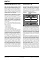
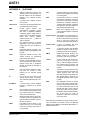
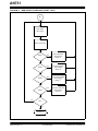
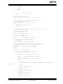
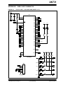
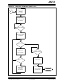
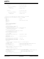
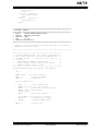
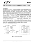
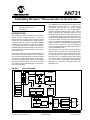
The application note presented here is based on the
block diagram shown in Figure 1. It consists of the
PIC16F87X microcontroller, the Seiko iChipTM
S-7600A TCP/IP stack IC, and the ISOmodemTM
Si2400 and Si3015 DAA from Silicon Labs. Each of
these components was specifically selected for this
application because of the feature set it provides. Each
of the following sections will present the reasons for
selection. The sample applications include both a web
server and a client. The web server stores the HTML
page in an external serial EEPROM and dynamically
inserts temperature and potentiometer settings into the
HTML file as it is being sent. The client application
mimics a vending machine that uploads status information at predefined intervals.
Rodger Richey/Steve Humberd
Microchip Technology Inc.
Chandler, AZ
INTRODUCTION
The market for products or services that are Internet
related is HOT! Increased amounts of money and
design resources are being thrown at these products
and services. One significant portion of this trend is to
embed the Internet or, in other words, make embedded
products have the capability to connect to the Internet.
It is estimated that by the year 2005, the number of
embedded applications with the ability to connect to the
Internet will be larger than the number of PCs by a factor of 100 or more.
This application note was written with the assumption
that the reader has a basic level of knowledge of Internet protocols. There are many good books on the market that describe the Internet and all the various
protocols used. It is suggested that the reader obtain
one of these books to understand what the protocols
are used for and how they relate to other protocols.
Appendix A is a dictionary of the terms used in this
application note.
The latest in PDAs and cellular telephones allow the
user to access stock quotes, sports scores, E-mail, and
more. The other advantage of the movement to embed
the Internet is enabling client devices, such as appliances and vending machines, to connect to the Internet
and upload status information. The price for such products is being reduced dramatically due to the introduction of new technology.
FIGURE 1:
BLOCK DIAGRAM
Network Stack
MPU Interface
S-7600A
TCP
UDP
IP
PPP
PIC16F877
SRAM Interface
MSSP
CCP
A/D
USART
Physical Layer
SRAM
10 Kbytes
Interface
1-byte
Buffer
16-byte
FIFO
UART
Microcontroller
Ring Detect
DSP
Si2400
ISOcap
Interface
DC/AC
Termination
AFE (Codec)
TIP
External
Discretes
RING
Si3015
2000 Microchip Technology Inc.
Preliminary
DS00731A-page 1
AN731
EMBEDDED WEB SERVER VS. CLIENT
MICROCONTROLLER
When most people think of the Internet, they think
about viewing web pages filled with information. A computer of some sort provides the necessary resources
required to support a web server. The computer has
significant hard disk space to hold the web pages and
ancillary data files such as data sheets, application
notes, etc. It also has a high-speed communications
interface such as a T1 line, a 56K modem, etc., that can
serve this information to a user quickly.
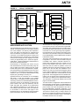
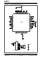
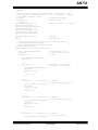
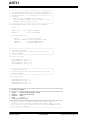
The microcontroller is the primary component of the
application, not necessarily a part of the Internet communications. In some cases, it may be advantageous
to offload the Internet communications to an external
device, so the microcontroller can focus on the details
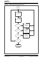
of the application, as well as the application layer of the
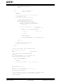
Internet Protocol Stack (see Figure 2).
FIGURE 2:
Embedded systems are quite different from standard
web servers. They have limited resources in terms of
memory space and operating speed. Embedded systems usually work with a few kilobytes, up to several
megabytes of memory and operate up to 40 MHz. Typical PCs have several gigabytes of memory storage
and are starting to operate in the gigahertz range.
Therefore, web servers are not really practical for
embedded applications, but the embedded web client
is very practical.
DNS
Price for each item
Number of items left
Amount of deposited money
Amount of money available for change
One could also argue that the machine could keep
track of the name or type of items that it is dispensing.
On a preset interval (such as once a night between
11 PM and 4 AM), the vending machine would dial out
and make a connection to a local Internet Service Provider (ISP). The machine would then connect to a
server and upload all the information. If the machine is
out of change, full of deposited money, or needs
restocking, a report can be generated detailing exactly
what is required. The service person can now make
one trip to the machine because they know exactly
what that particular machine needs. The machine can
also call out if an operating error has been detected.
This may include the vending machine is tilted to
improperly dispense items, or lights have burned out. A
service report is generated and the service person
knows exactly what is needed to fix the problems. Since
we have established a full duplex link, the embedded
Internet connection can provide additional benefits,
such as reprogramming the microcontroller with new
firmware to fix bugs, or new pricing structure for items.
DS00731A-page 2
FTP
UDP
HTTP
TCP
ICMP
IP
One of the most viable embedded web client applications is a vending machine. The microcontroller keeps
track of all functions:
•
•
•
•
INTERNET PROTOCOL
STACK
PPP
ETHERNET
One feature that provides the most flexibility for an
embedded application is FLASH-based program memory. FLASH program memory provides the capability to
reprogram portions of the firmware remotely over the
Internet connection. The sections of firmware that can
be reprogrammed not only include the instructions, but
also sensor calibration tables, IDs, and application
lookup tables. For instance, the pricing for the vending
machine items may be stored in a lookup table that can
be reprogrammed by the server when a connection is
made.
When choosing a FLASH-based microcontroller, it is
important to select one with the features that can facilitate this type of remote reprogramming operations.
The microcontroller must be able to modify its own firmware without the need for external circuitry. It must also
have the capability to reprogram without interrupting
the operation of the application. In other words, the
peripherals and internal clocks must continue to operate and queue events, while the microcontroller is
reprogramming memory locations.
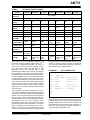
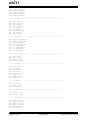
One example of this type of microcontroller is the
PIC16F87X family of products from Microchip Technology. Table 1 shows the current family of products.
These products provide a migration path for memory
size and feature set within a given footprint (28 or 40
pins).
Preliminary
2000 Microchip Technology Inc.
AN731
TABLE 1:
Features
PIC16F87X PRODUCT FAMILY
PIC16F870
PIC16F871
PIC16F872 PIC16F873
Operating
Frequency
PIC16F874
PIC16F876
PIC16F877
DC - 20 MHz
Resets
Power-on Reset, Brown-out Reset, Power-up Timer, Oscillator Start-up Timer
FLASH Program
2K
Memory
2K
2K
4K
4K
8K
8K
Data Memory
128
128
128
192
192
368
368
EEPROM Data
Memory
64
64
64
128
128
256
256
Interrupts
10
10
11
13
14
13
14
I/O Pins
22
33
22
22
33
22
33
Timers
3
3
3
3
3
3
3
Capture/Compare/PWM
1
1
1
2
2
2
2
Serial
Communication
USART
USART
MSSP
MSSP,
USART
MSSP,
USART
MSSP,
USART
MSSP,
USART
Parallel
Communication
PSP
10-bit A/D
Channels
5
Instruction Set
35
Instructions
Packages
28-pin DIP,
SOIC,
SSOP
8
PSP
5
5
8
5
8
40-pin DIP
40-pin DIP
28-pin DIP,
28-pin DIP
28-pin DIP,
44-pin PLCC,
44-pin PLCC, SOIC,
SOIC
SOIC
TQFP
TQFP
SSOP
These devices have the standard complement of
peripherals including USARTs, Master Mode I2CTM,
SPITM, A/D, Capture/Compare/PWM and Timers. It
also has up to 8K words of FLASH program memory,
up to 368 bytes of RAM and 256 bytes of data
EEPROM memory. By combining both a data
EEPROM and FLASH program memory, the designer
has the flexibility to store data in the appropriate place.
Information that is updated frequently can be stored in
the data EEPROM, which has increased endurance
over the FLASH program memory. This data can be
modified without interrupting the operation of the application. Other information that is rarely changed can be
stored in FLASH program memory. When updating
these locations, the microcontroller ceases to execute
instructions, but continues to clock the peripherals and
queue interrupts.
The programming operation is self-timed, i.e., an internal clock source applies the high voltage to the memory
cells to erase and/or write the data for a predetermined
amount of time. This frees the designer from the task of
timing the event. It also reduces the risk of the high voltage being applied too long, which damages or reduces
the endurance of the cell, or not long enough, which
does not fully program the memory location. The actual
programming code is shown in Example 1. This simple
piece of code assumes the addresses of the memory
location and data have been loaded before being
called. The only difference between modifying FLASH
2000 Microchip Technology Inc.
PSP
40-pin DIP
44-pin PLCC,
TQFP
program memory and data EEPROM memory is the
setting of a single bit. This bit needs to be configured
only once and all subsequent programming operations
will be directed to the desired memory.
EXAMPLE 1:
SELF-TIMING CODE
bsf
STATUS,RP1
;Switch to Bank 3
bsf
STATUS,RP0
bsf
EECON1,WREN
;Enable write
movlw
55h
;5 instruction
mowf
EECON2
;sequence to
movlw
AAh
;initiate the
movwf
EECON2
;write operation
bsf
EECON1,WR
;to memory
nop
nop
The programming sequence contains a five-instruction
sequence that must be executed exactly to initiate the
programming cycle. If this sequence is not followed, the
programming operation will not start. Also included is a
write enable bit. If this bit is not set, then writes will not
take place. These two features provide a measure of
protection against inadvertent writes.
Preliminary
DS00731A-page 3
AN731
The other part of the remote programming operation
handled by the microcontroller is the bootloader. This
portion of the firmware accepts data from the outside
world and controls the erase/program operations. It
may also include security features for entering the programming mode. One feature that is a must in all bootloaders is the capability to recover when the
communications medium is interrupted. If the Internet
connection, or telephone connection is interrupted, the
microcontroller must be smart enough to recover. The
application note AN732 provides one method for recovery. The security portion is not implemented because
requirements are heavily dependent on the application.
TCP/IP STACK
The Internet protocol used varies depending on the
application. Figure 2 shows the standard Internet protocol stack. In most embedded systems, a dial up connection will be used and, therefore, the Network
Access Layer will be Point-to-Point Protocol (PPP).
This protocol encapsulates the other protocols for
transmission over serial links such as modems. This is
the most commonly used protocol for dial-up networks
such as America Online Inc. or Compuserve®. PPP
performs three main functions. It encapsulates IP and
TCP/UDP packets with a header and checksum and
inserts escape characters to distinguish data bytes
from flag bytes. It also configures the link between the
two peers, including compression and maximum
receive units (MRUs). Finally it configures the network
connection allowing multiple network protocols and
negotiation of an IP address. PPP does not specify a
server or a client. It assumes there are two peers, both
of which have equivalent authority in the connection.
PPP also handles user name and password authentication. Two protocols are supported: Password
Authentication Protocol (PAP) and Challenge Handshake Authentication Protocol (CHAP). Once the link
parameters are negotiated, PPP is used to transfer
data packets between the two hosts and terminate the
connection, once all the data has been sent.
address and ports. Each of the source and destination
devices have different IP addresses, but both devices
must be using the same port to be able to communicate
to each other. The number of the port used usually
determines what type of application layer is used for
communication. These port numbers may be from 0 to
65536, but some are already assigned to specific applications. A port number of 80 is usually assigned to
HTTP. Therefore an HTTP server will listen to port 80
for any incoming data. The HTTP server will accept
data packets, if the destination IP address and the port
number match. A large data file will be broken up into
many packets of data. TCP is capable of receiving
these packets in any order and then reconstructing the
original file. TCP also has the same type of checksums
that are involved with UDP.
TCP has been deemed to be the more reliable method
of transferring data over the Internet, but it really
depends on the type of data being transferred between
the two devices. One factor is the relative importance
of the data. If a device is transmitting temperature measurements every couple of minutes, losing one reading
may not be as severe as losing one frame of data in an
image file. Temperature changes very slowly and the
fact that another reading will be sent in a couple of minutes would allow extraction of the missing reading from
the previously received reading and the current reading. UDP can come close to achieving some of the features of TCP, but it involves a lot of work to provide the
handshaking necessary to create a reliable connection.
Many microcontroller manufacturers have software
libraries that support TCP and UDP. However, most of
these implementations have documented limitations
that may cause increased overhead to transmit and
receive data using Internet protocols. The following bullets list some of these limitations documented by a
manufacturer for their UDP and TCP software implementations.
The transport layer provides the basic communication
between a server and a client. User Datagram Protocol
(UDP) is not based on making connections between
the hosts. In other words, the host receiving a packet
from another host does not acknowledge the reception.
Therefore, the transmitting host has no indication of
whether the packet made it to its destination. The
acknowledgment can be a return UDP packet from the
receiving host. However, this is not included in the UDP
specification and requires additional overhead for both
hosts. UDP is the best protocol for use when transmitting small amounts of data or for regular transmissions
of small data packets. Each UDP packet is encapsulated with a header and a checksum to provide some
error checking.
• The UDP & TCP headers contain a checksum
field. This checksum is computed for the data in
the packet, yet it is transmitted in the header. This
implementation transmits the packet with an
incorrect checksum, calculates the checksum as
the packet is sent, and sends the packet again
with the correct checksum.
• The implementation does not handle fragmented
packets meaning that packets that arrive out of
sequence are handled as sequential packets.
This causes the resulting data to be corrupted.
The proposed method assumes that if the packet
size is minimized to 256 bytes, then fragmentation
is not likely to occur.
• The implementation does not send a terminate
acknowledge packet, which forces the host on the
other end to time-out in order to recognize that the
connection was terminated.
Unlike UDP, Transmission Control Protocol (TCP) provides a flow controlled, connection based host-to-host
transfer of data. TCP provides connections based on IP
Rather than implement a software protocol stack that
has these type of limitations, the designer may choose
to use an external TCP/IP stack device. This device
DS00731A-page 4
Preliminary
2000 Microchip Technology Inc.
AN731
should relieve the designer of working around limitations and allowing more capabilities to be built into the
product. The TCP/IP stack device should minimally
implement the Network Access Layer, Internet Layer,
and the Transport Layer as shown in Figure 2, freeing
up program memory to implement protocols for the
Application Layer. A minimal software implementation
of the Point-to-Point Protocol (PPP), Internet Protocol
(IP), ICMP, and UDP/TCP would require approximately
5 Kbytes of program memory and at least 4 Kbytes of
data memory. The now vacant program memory could
be used for Simple Mail Transfer Protocol (SMTP), Post
Office Protocol version 3 (POP3), or Hyper Text Transfer Protocol (HTTP).
The S-7600A TCP/IP Stack IC from Seiko Instruments
was designed specifically for this type of market. It integrates the TCP/IP Stack engine, 10 Kbytes of RAM,
microcontroller interface and UART into a single chip.
Once configured, it acts like a data buffer. Data to be
transmitted, up to 1024 bytes, is stored in the internal
RAM buffer and the TCP/IP engine appends the various headers and checksums. It then transmits this
packet from the UART. When packets are received, the
TCP/IP engine determines if the IP address and port
number match those set during configuration, calculates and verifies the checksums, and transfers the
data contents of the packet to a buffer. It then uses
interrupt lines to indicate there is data available to the
microcontroller.
The complete list of features for the S-7600A are:
• Implements PPP, IP, TCP, UDP and PAP
• Two general purpose sockets
• Two parallel interfaces (68K/x80 Motorola/Intel
MPU bus) or synchronous serial interface
• On-chip UART physical layer transport interface
• 256 kHz typical operating frequency
• Low power consumption (0.9 mA typical, 1.0 µA
standby)
• 2.4 V to 3.6 V operating voltage range
The designer now has full Internet capabilities without
any of the limitations of the software implementations.
The bulk of the program memory on the microcontroller
can now be used for the main application and also for
implementing some of the Application Layer protocols
previously described. The size of the program memory
is now dependent on the application and can be scaled
accordingly. The S-7600A delivers Internet capability to
the bulk of microcontrollers that were previously constrained due to program and data memory size.
The data sheet for the S-7600A can be downloaded
from their website at http://www.seiko-usa-ecd.com.
There is also a designer's kit available in the form of a
PC card. It includes some software library routines to
control and interact with the S-7600A. Besides the data
sheet, there are manuals for exact protocol implementations, software API for the developer's kit, and example source code available for download.
2000 Microchip Technology Inc.
MODEM
The last key ingredient is the communications medium
used to connect to the Internet. The type of medium
selected is highly application dependent but can
include:
•
•
•
•
Wireless
Cellular
Power Line Carrier
POTS (Standard telephone lines)
All of these mediums require some infrastructure to be
in place before the embedded device can communicate. Both wireless and cellular transceivers require
antennas to be placed in the surrounding area to provide the communication channel. While most areas
have some of this infrastructure in place, there are
areas that are not completely covered. Everyone has
probably experienced this with a cellular telephone at
one time or another. Power line carrier also requires
infrastructure to be in place. There has to be some sort
of transceiver at the other end of the power lines that
communicates with the embedded application. This
infrastructure for this technology does not currently
have the widespread use that wireless or cellular offer
and therefore, the costs to build this infrastructure
would be substantial. The standard telephone lines are
everywhere. The telephone poles, wiring, relay stations, etc., are already in place. The cost of building the
infrastructure is zero and therefore, makes the most
sense for the bulk of embedded applications. There will
be applications where the other mediums are needed,
but the application will be able to justify and therefore,
absorb the additional costs associated with using the
respective mediums.
Usually, the telephone modem technology is significantly less expensive than that of other mediums. It
also fits better into embedded applications due to size
and power consumption. The key to modem selection
is to find one that is highly integrated, i.e., smaller in
size. This is important due to the fact that most embedded applications are small. This modem should be
easy to use and provide all the necessary features in a
single package. Fortunately, the folks at Silicon Laboratories have developed an embedded modem that may
be one of the best designs ever to hit the streets. The
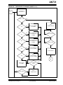
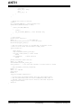
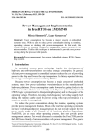
first feature that stands out is the size. Figure 3 shows
the size of the Silicon Labs design compared to a standard modem design. NO relays. NO optoisolators. NO
transformers. This design has the Si2400 modem and
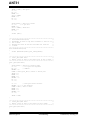
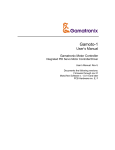
the Si3015 DAA chip and some passive devices (resistors, capacitors, diodes and transistors). The secret is
in the ISOcapTM Technology, used to transfer control
and data over a capacitive interface as shown in
Figure 4. This interface provides a low cost solution
based off standard high voltage capacitors and over
2400 V of isolation. The cost to implement this design
in volume should be less than $9.00.
Preliminary
DS00731A-page 5
AN731
After recovering from the size shock, the impressive list
of features makes this product a winner.
The list includes:
• AT command set support
• V.21/Bell 103, V.22/Bell 212A, V.22bis, V.23, & SIA
support
• Caller ID detection and decode
• Call progress support
• Voice codec
• Globally programmable DAA (FCC, CTR21,
NET4, JATE, etc.)
• Parallel phone detect
• Wake-up on ring
• Overcurrent detection
Never before has the embedded control electronics
industry seen a modem design this integrated AND this
small AND this CHEAP! But one question remains; why
2400 baud? Isn't that baud rate a little slow to use for
Internet applications, even embedded Internet applications? The answer is quite simple. If the application was
a web server, then yes, a 2400 baud modem is not
practical. But it was already established that a web
server was not practical for the embedded world. A typical embedded application will only transfer several
hundred bytes of data. When looking at the complete
connect and transfer time of one session, a 2400 baud
modem will connect in approximately three seconds
and upload 200 bytes of data in 0.833 seconds (200
bytes x 10 bits/byte x 1s/2400 bits) for a total of 3.833
FIGURE 3:
seconds. A 56K modem will connect in approximately
15 seconds and transfer 200 bytes in 0.036 seconds
(200 bytes x 10 bits/byte x 1s/56000 bits). This calculation shows that a 2400 baud modem can connect to the
ISP, dump the data to the server and disconnect before
the 56K modem even establishes a connection to the
modem on the other end of the line. It just doesn't make
sense, especially when you consider the price of the
2400 baud modem versus the 56K modem.
Another feature of a telephone-based system is choosing the ISP to make the Internet connection. Everyone
hears about the high speed Internet links such as cable
modems. Most providers are targeting customers that
want high-speed access for web browsing. According
to the estimates, this market which itself is very large,
will be dwarfed by the embedded devices. Some companies are starting to realize this fact and are catering
towards these embedded applications with low speed
modems. One such company is iReady with their
iready.net service. It caters to all facets of Internet connectivity, but includes the service for embedded low
speed modem applications.
The data sheet for the Si2400/Si3015 can be downloaded from the Silicon Laboratories website at
http://www.silabs.com. They also make a modem evaluation board that has a complete modem implementation and an RS-232 interface for use with a PC. The
user's manual for the evaluation board is also available
from the website and provides some suggested layout
guidelines.
MODEM SIZE COMPARISON
Si2400
Modem
Typical
PC Card
Modem
DS00731A-page 6
Preliminary
2000 Microchip Technology Inc.
AN731
FIGURE 4:
ISOcap™ INTERFACE
ISOcap™
To
Host
Ring Detect
Digital
Interface
DC Termination
Isolation
Interface
MicroController
Isolation
Interface
Control
Data
AC Termination
Ring Impedance
To
Telephone
Line
Ring Threshold
DSP
AFE
Si2400
Si3015
WEB SERVER APPLICATION
The embedded web server application is more for show
and tell. As mentioned before, it is not really a practical
use of the hardware. The memory sizes required to
serve web pages and data files far outweighs that
which can be found on a typical microcontroller. In fact,
if the price of non-volatile semiconductor memory and
that of hard drives were compared, the results would
show that the average price per megabyte of FLASH
memory is approximately $1.00 – $2.00 and approximately $0.01 – $0.05 for hard drives. That equates to a
ratio of 40:1 favoring hard drives.
Demonstrations of embedded web servers are just
that, demonstrations of Internet connectivity. They are
easy to design and require nothing more than a web
browser and a phone line to demonstrate the capabilities. Demonstrating a client application such as a vending machine is more difficult. Toting around a vending
machine in your car for product demonstrations really
impacts your gas mileage. It’s heavy, too.
Appendix B shows the schematic for the embedded
web server. It uses the PIC16F877, the S-7600A
TCP/IP stack IC, the Si2400 modem and Si3015 DAA.
The design uses 24LCxx serial EEPROM that comes in
sizes from 16 bytes up to 32 Kbytes. It holds the ISP
phone number, user name and password, and the
HTML web page. Also included are a potentiometer
and a DS1721 temperature IC. This design can be
found using the link: http://198.175.253.101. It takes up
to 30 seconds or more for the web page to load.
Remember that we are transmitting several thousand
bytes of information over the Internet at 2400 baud.
2000 Microchip Technology Inc.
Hybrid
The schematic for everything but the modem and serial
port interface is shown on the schematic in Appendix B.
This design was actually built around a modem evaluation board from Silicon Laboratories. Since the modem
must meet FCC or other governing body regulations,
the schematics are not provided for the modem evaluation board. The schematics and layout considerations
for the Si2400/Si3015 can be obtained from the Silicon
Laboratories website.
The source code and flowchart for the web server are
in Appendix C. The source code was written using the
C-Compiler from Custom Computer Services Inc.
(CCS). More information about the compiler can be
found on their website at http://www.ccsinfo.com. The
web server has two modes of operation. One is the
standard web server mode where the device makes a
phone call to the local ISP and establishes an IP
address. The user may access the web page by typing
in the IP address displayed on the LCD display into any
web browser. It takes 30 to 40 seconds for the web
page to load. The web page shows some variable information, such as number of hits, temperature where the
web server is, IP address, and a potentiometer setting.
This information is dynamically inserted into the web
page as it is transmitted.
The other mode is a configuration mode, that allows the
ISP information and web page to be downloaded into
the serial EEPROM. The ISP information includes the
phone number, user name and password. The size of
the serial EEPROM is application dependent. It can
range from 16 bytes (24LC00) to 32 Kbytes (24LC256).
The board is currently using a 16 Kbyte device, the
24LC64. To configure the web server, the RS-232 interface on the modem evaluation board is connected to
the USART module on the PIC16F877.
Preliminary
DS00731A-page 7
AN731
Any terminal program will work, as the PIC16F877 displays a text menu that allows the user several options:
1.
2.
3.
4.
5.
Enter user name
Enter password
Enter phone number
Download HTML file
Or exit configuration mode
Several modifications had to be made to the modem
evaluation board. It was originally designed to interface
the serial port on the PC directly to the modem. Using
a terminal program, the user could make or receive
phone calls. This interface was hacked to allow stacking of the control board on top of the modem evaluation
board. These modifications include:
1.
Each piece of information has specific memory locations reserved in the serial EEPROM. 32 bytes are
reserved for both the user name and password. The
ISP phone number takes an additional 16 bytes.
Finally, 32688 bytes are available to store the HTML
file. The serial interface must use hardware flow control, otherwise the USART buffer will be overrun, due to
the programming time required by the serial EEPROM.
The application provides lots of status information.
Messages are displayed when a call is being made, a
dial tone is detected, a ring occurs, a busy phone line
is detected, or when the modem finally makes a connection. The display will show the IP address once the
modem has made the connection. There are also a
couple of LEDs that indicate the status of the web
server. The first LED shows if the modem is connected.
The second LED flickers when the web server is being
accessed.
2.
3.
4.
5.
6.
7.
Drill holes through the traces from U3 pins 24
and 25 and remove residual traces
Cut the copper away from the holes on the bottom
Cut the traces on the bottom of the board going
to JP3 pins 5 and 7
Lift U1 pin 7
Connect a jumper wire from U3 pin 24 through
hole to JP3 pin 7
Connect a jumper wire from U3 pin 25 through
hole to JP3 pin 5
Remove shorting jumpers from JPIO 1 and 3
and JP4
The controller board is then bolted directly on top of the
evaluation board and makes the necessary connections from the S-7600A to the modem, the modem to
the microcontroller, and the microcontroller to the
RS-232 interface IC.
Special characters are used to allow the web server to
insert variable data into the web page. The following
information can be displayed when these characters
are found in the HTML web page:
• %a displays the IP address for web page reload
function
• %c inserts the current temperature in degrees
Celsius
• %f inserts the current temperature in degrees
Fahrenheit
• %h displays the number of times the web site has
been accessed
• %p inserts the current value of the potentiometer
DS00731A-page 8
Preliminary
2000 Microchip Technology Inc.
AN731
CLIENT APPLICATION
This application represents a typical embedded Internet application, where the embedded device is the client and is capable of connecting to a server to upload
information and download new information, or firmware. In this case, a vending machine that receives
new information. The vending machine application has
an LCD display that shows the current items in the
machine and the price for each. It will “dispense” items
until the machine is empty. At any time, a push-button
switch may be pressed to start the connection to the
server via the Internet. The modem dials an ISP, makes
a connection to the server, and receives new names
and prices of items to be dispensed.
The hardware design is a subset of the web server
application. Appendix D shows the schematic for the
client application. This design removes the serial
EEPROM, potentiometer and temperature IC. It adds
some push-button switches for the additional user
interface required. It uses the same modem evaluation
board as the web server with all the same modifications.
The source code and flowchart for the client is given in
Appendix E. This source code was also written using
the CCS C-Compiler. The vending machine has two
modes of operation. It has the standard operating
mode of reading the push-button switches and “dispensing” items based on which button is pressed. It
tracks the number of items remaining in the vending
machine and the total amount of money collected. The
second mode of operation is the Internet connection.
Most of the code to interface with the S-7600A is the
same as the web server, with the exception that it is
now a TCP client instead of a TCP web server. It must
also know what the IP address and port number of the
server is before it can make a connection to the server.
This means that more than a web browser is required
to complete the connection on the server side. There
must be a program running on the server that listens to
a port. Once connected, the transfer of information may
take place between the client and the server.
0 and 9. This index is used by the server to extract the
next vending machine item names and prices out of a
database. The format of this data is ~ ~ # ~ ~ where #
is the index value 0-9. The server will then respond with
the new names and prices in the following format:
~ <name1>; <name2>; <price1>; <price2>;
The tilde character is used to denote the start of the
string. Each of the names and prices is a null terminated ASCII string and they are delimited using semicolons. Once the client receives this information and
updates the data EEPROM, the connection with the
server is terminated. At this point, the client must be
reset through a MCLR Reset, or by cycling the power.
It now switches back to the normal mode of operation,
using the new names and prices provided by the web
server. Other information, such as total amount of
money collected and the number of remaining items,
could have been transmitted back to the server, but the
application was kept simple for both the client and the
server. This interaction is highly application dependent
and can be easily adapted based on the system
requirements.
CONCLUSION
The move to embed the Internet is creating many new
and fascinating devices for all different types of markets. Cellular phones and PDAs are the latest devices
to add Internet capability. Soon many household appliances, such as refrigerators, will have Internet capability and these embedded applications will dominate the
Internet. These devices can Internet-enable any application that has already used most of the available
microcontroller resources to control the application. In
most cases, a microcontroller cannot afford to dedicate
5 Kbytes of program memory and a significant portion
of data memory for Internet connections. This need has
created devices such as the S-7600A and Si2400 specifically for the embedded Internet market.
FURTHER REFERENCE
In this application, the Internet connection provides the
names and prices of new items. Every connection to
the server downloads two new item names and prices
that are then programmed into data EEPROM. Since
these are values that could change frequently, the data
EEPROM was used for nonvolatile storage of the information, due to the higher endurance. The same methods presented here can be used in conjunction with the
bootloader of AN732 to download new source code into
FLASH program memory.
RFC1332, The PPP Internet Protocol Control Protocol
The data that is transferred between the client and the
server has some handshaking built in. Once the connection is established, the client waits for a response
from the server. The value of the data is not important,
only the response from the server, so the buffer is emptied without any processing of the information. The client now responds with an index number between
RFC959 FTP
2000 Microchip Technology Inc.
RFC1334, PPP Authentication Protocols
RFC1661, The Point-to-Point Protocol
RFC1662, PPP in HDLC-like Framing
RFC1700, Assigned Numbers
RFC793, TCP
RFC821, SMTP
RFC1725, POP3
RFC792 ICMP
RFC791 IP
RFC768 UDP
"Internetworking with TCP/IP", Prentice-Hall, 1995,
Douglas E. Comer
Preliminary
DS00731A-page 9
AN731
APPENDIX A:
ARP
GLOSSARY
Address Resolution Protocol: The
TCP/IP protocol that translates an
Internet address into the hardware
address of the network interface
hardware.
client
A program that requests services
from a server.
client/server
A style of computing that allows work
to be distributed across hosts.
DNS
Domain
Name
System:
The
name/address resolution service
that uses a distributed database
containing address. DNS makes it
easier to refer to computers by name
rather than numeric address
(www.microchip.com -- instead of
198.175.253.68)
FTP
File Transfer Protocol: A TCP/IP
application, service, and protocol for
copying files from one computer to
another.
HTML
HyperText Markup Language: The
language used to write pages for the
Internet.
HTTP
HyperText Transfer Protocol: The
TCP/IP protocol for transferring
pages across the Internet.
ICMP
Internet Control Message Protocol:
The TCP/IP protocol used to report
network errors and to determine
whether a computer is available on
the network.
Internet
The international collection of internets that use TCP/IP to work
together as one immense logical
network.
IP
One of the two main parts of the
TCP/IP protocol suite. IP delivers
TCP and UDP packets across a network.
IP Address
A 32-bit unique numeric address
used by a computer on a TCP/IP
network.
LCP
Link Control Protocol: The protocol
that negotiates the parameters used
by the link between two computers
and is protocol within PPP.
NCP
Network Control Protocol: The protocol within PPP that negotiates the
type of network connection made by
the two computers.
POP3
DS00731A-page 10
Post Office Protocol version 3: The
protocol that you use to download
e-mail from a POP3 mail server to
your computer.
port
A number used by TCP and UDP to
indicate which application is sending
or receiving data.
PPP
Point-to-Point Protocol: A protocol
that provides a serial line connectivity (that is, a dial-up with a modem)
between two computers, between a
computer and a network, or between
two networks. PPP can handle several protocols simultaneously.
protocol
Rules and message formats for
communication between computers
in a network.
protocol layers The divisions of a hierarchical network model. Each layer performs a
service on behalf of the layer directly
above it. Each layer receives services from the layer directly below it.
protocol stack
A group of protocols that work
together across network layers.
server
A computer program that provides
services to clients, and/or the computer that runs the server program.
SMTP
Simple Mail Transfer Protocol: The
TCP/IP protocol for sending and
receiving e-mail across a network.
socket
A data structure that allows programs on an internet to communicate. It works as a pipeline between
the communicating programs and
consists of an address and a port
number.
TCP
Transmission Control Protocol: One
of the two principal components of a
TCP/IP protocol suite. TCP puts
data into packets and provides reliable packet delivery across a network (packets arrive in order and are
not lost).
UDP
User Datagram Protocol: A TCP/IP
protocol found at the network (internet) layer, along with the TCP protocol. UDP sends data down to the
internet layer and to the IP protocol.
Unlike TCP, UDP does not guarantee reliable, sequenced packet delivery. If data does not reach its
destination, UDP does not retransmit as TCP does.
Most definitions provided by the book TCP/IP for Dummies 3rd Edition by Candace Leiden and Marshall
Wilensky and published by IDG Books Worldwide, Inc.
ISBN 0-7645-0473-8
Preliminary
2000 Microchip Technology Inc.
AN731
APPENDIX B:
FIGURE B-1:
EMBEDDED WEB SERVER SCHEMATICS
TCP/IP SERVER MODEM (SHEET 1 OF 3)
+3 V
C2
U1
C3
12
.1 µF
R1
.1 µF
35
VDD
RE2
VDD
RE1
10 k
RE0
2
MCLR
MCLR
RD7
+3 V
RD6
3
4
RA1
R4
C4
10 k
5
RS
.1 µF
6
RA3
7
RESET
8
BUSYX
INT1
+3 V
37
RB1
RB2
41
RB4
10 k
1
4
2
3
42
RB5
S1
R10
43
RB6
MCLR
44
RB7
470
38
39
RB3
R9
36
RA0
RD5
RA1
RD4
RA2
RD3
RA3
RD2
RA4
RD1
RA5
RD0
RB0
RC7
RB1
RC6
RB2
RC5
RB3
RC4
RB4
RC3
RB5
RC2
RB6
RC1
RB7
RC0
OSC2
S2
1
4
2
3
11
10
9
33
32
31
30
24
23
22
21
29
27
CS
WRITEX
READX
SD7
+3 V
SD6
+3 V
SD5
D2
SD4
D1
SD3
SD2
SD1
SD0
R8
R5
300
300
RXD2
TXD2
26
25
20
SDA
SCL
19
18
16
CLK1
CTS
15
R11
RA1
13
470
34
VSS
OSC1
14
OSC1
JP2
VSS
MCLR
PIC16F877
+3 V
1
2
3
+3 V
U4
1
2
3
4
A0
A1
R6
VCC
WP
A2
SCL
GND
SDA
8
7
4.7 k
6
5
24LC08B_DIP
RB7
4
RB6
5
6
R7
4.7 k
SCL
SDA
U7
C11
.1 µF
SDA
SCL
1
2
3
4
SDA
+3 V
VCC
SCL
A0
Tout
A1
GND
A2
RJ11_6PIN
8
7
6
C10
5
.1 µF
DS1721_SO8
2000 Microchip Technology Inc.
Preliminary
DS00731A-page 11
AN731
FIGURE B-2:
TCP/IP SERVER MODEM (SHEET 2 OF 3)
+3 V
C1
SD7
37
SD7
NC
TI2
SD6
38
SD6
39
40
41
TI1
VDD
SD4
SD5
42
SD5
43
44
SD4
SD2
SD1
SD3
45
SD3
SD2
46
S-7600A
RI
VSS
RXD
READX
DCD
C86
DTRX
CS
DTSX
RS
36
BUSYX
35
34
INT1
33
32
WRITEX
31
+3 V
30
29
READX
28
27
26
CS
RS
T14
25
24
T15
23
T17
22
13
T16
T13
VDD
TXD
T07
TXD
12
PSX
21
11
U2
DSRX
T01
10
WRITEX
20
9
CTSX
19
DCD
8
INTCTRL
T02
RXD
VSS
T03
7
INT1
18
6
CLK
17
5
INT2X
T04
4
TEST
16
3
T05
CLK
BUSYX
T06
2
RESET
15
1
14
RESET
SD1
47
SD0
48
SD0
.1 µF
+3 V
C5
.1 µF
U8
11
OSC1
10
CLR
9
CLK QA 7
QB
6
QC
5
QD
3
QE
2
QF
4
QG
13
QH
12
QI
14
QJ
15
QK
QL 1
+3 V
J1
1
CLK
CLK1
for U8
C12
2
3
.1 µF
SIP_3
SN74HC4040DW
DS00731A-page 12
Preliminary
2000 Microchip Technology Inc.
AN731
FIGURE B-3:
TCP/IP SERVER MODEM (SHEET 3 OF 3)
U6
LM2937
1
JP4
IN
+3 V
+3 V
OUT
5V
3
COM
+5 V
C9
2
.1 µF
D3
J3
U3
LM2937
1
1
IN
3
.1 µF
DJ005B
3
+3 V
18
16
14
12
B1
B2
B3
COM
C6
2
3.3 V OUT
C7
C8
220 µF
.1 µF
2
LCD1
LED 17
5
B1
B2
15
6
B3
16
+5 V
18
19
E
R/W
DB4 14
DB5 13
LCD_SIMM
R/S
VEE
DB6 12
DB7 11
VCC
VSS
B4
B5
B6
B7
+3 V
R2
U5:A
10 k
JP1
1
3
TXD2
RXD2
RESET
CTS
5
7
9
11
13
15
1
2
P1
P2
P3
P4
P5
P6
2
4
6
8
RB1
RB2
RB3
4
6
DCD
OE
A1
A2
A3
A4
Y1
Y2
Y3
Y4
74LVTH240
8
P7
P8
U5:B
10
P9
P10
12
P11
P12
14
P13
P14
P15
P16
16
TXD
19
RXD
OSC1
RB4
RB5
RB6
RB7
11
13
15
17
OE
A1
A2
A3
A4
Y1
Y2
Y3
Y4
9
7
5
3
B4
B5
B6
B7
74LVTH240
2000 Microchip Technology Inc.
Preliminary
DS00731A-page 13
AN731
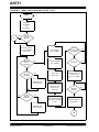
FIGURE B-4:
WEB SERVER FLOWCHART (SHEET 1 OF 3)
START
B
D
CONFIGURE
PIC16F877,
SERIAL E2, AND
TEMP SENSOR
PPP
AND MODEM
STILL
CONNECTED?
NO
YES
MENU
BUTTON
PRESSED?
B
YES
ENABLE SOCKET,
USE HTML PORT 80,
TCP SERVER
A
NO
PPP
AND MODEM
STILL
CONNECTED?
CONFIGURE MODEM
AND S-7600A
RESET MODEM
AND S-7600A
NO
YES
READ USER NAME,
PASSWORD, AND
WRITE TO PAP
REGISTER
NO
RESET AND
ENABLE PPP
SOCKET OPEN?
YES
NO
READ PHONE NUMBER
AND SEND TO MODEM
TO DIAL
DATA RECEIVED?
YES
YES
READ
DETECT
BUSY OR NO LINE
OR CARRIER?
POTENTIOMETER
AND TEMPERATURE
NO
NO
CONNECT?
YES
ENABLE PAP RELEASE
C
CONTROL OF
UART TO S-7600A
NO
DS00731A-page 14
IP
ADDRESS
CHANGE?
YES
Preliminary
READ AND DISPLAY
IP ADDRESS
2000 Microchip Technology Inc.
AN731
FIGURE B-5:
WEB SERVER FLOWCHART (SHEET 2 OF 3)
READ BYTE
2
FROM SERIAL E
C
CHAR
== 0?
YES
NO
%a
YES
WRITE IP ADDRESS
TO S-7600A
YES
WRITE TEMPERATURE
IN CELSIUS TO
S-7600A
SEND
S-7600A BUFFER
NO
%c
NO
NO
YES
YES
%f
BUFFER EMPTY?
WRITE TEMPERATURE
IN FARENHEIT TO
S-7600A
NO
SOCKET IDLE?
NO
YES
YES
%h
WRITE NUMBER OF
HITS TO S-7600A
CLOSE SOCKET
NO
YES
%p
WRITE
POTENTIOMETER
VALUE TO S-7600A
NO
WRITE VALUE
TO S-7600A
D
IS BUFFER
FULL?
NO
YES
YES
BUFFER EMPTY?
SEND
S-7600A BUFFER
NO
2000 Microchip Technology Inc.
Preliminary
DS00731A-page 15
AN731
FIGURE B-6:
WEB SERVER FLOWCHART (SHEET 3 OF 3)
A
PRINT MENU
SELECTIONS
READ CHARACTER
0X31?
YES
READ USERNAME
AND STORE IN
SERIAL E2
YES
READ PASSWORD
AND STORE IN
SERIAL E2
YES
READ PHONE NUMBER
AND STORE IN
SERIAL E2
YES
READ NEW WEB PAGE
AND STORE IN
SERIAL E2
NO
0X32?
NO
0X33?
NO
0X34?
NO
NO
ESC?
YES
RETURN TO ‘A’
IN SHEET 1
DS00731A-page 16
Preliminary
2000 Microchip Technology Inc.
AN731
Software License Agreement
The software supplied herewith by Microchip Technology Incorporated (the “Company”) for its PICmicro® Microcontroller is
intended and supplied to you, the Company’s customer, for use solely and exclusively on Microchip PICmicro Microcontroller products.
The software is owned by the Company and/or its supplier, and is protected under applicable copyright laws. All rights are reserved.
Any use in violation of the foregoing restrictions may subject the user to criminal sanctions under applicable laws, as well as to civil
liability for the breach of the terms and conditions of this license.
THIS SOFTWARE IS PROVIDED IN AN “AS IS” CONDITION. NO WARRANTIES, WHETHER EXPRESS, IMPLIED OR STATUTORY, INCLUDING, BUT NOT LIMITED TO, IMPLIED WARRANTIES OF MERCHANTABILITY AND FITNESS FOR A PARTICULAR PURPOSE APPLY TO THIS SOFTWARE. THE COMPANY SHALL NOT, IN ANY CIRCUMSTANCES, BE LIABLE FOR
SPECIAL, INCIDENTAL OR CONSEQUENTIAL DAMAGES, FOR ANY REASON WHATSOEVER.
APPENDIX C:
EMBEDDED WEB SERVER SOURCE CODE
/***************************************************************************
* Filename: MODEM_C.C
****************************************************************************
*
Author: Stephen Humberd/Rodger Richey
*
Company:Microchip Technology
*
Revision:RevA0
*
Date:
5-24-00
*
Compiled using CCS PICC
****************************************************************************
*
Include files:
*
16f877.h
*
f877.h
*
s7600.h
*
ctype.h
*
string.h
*
lcd_cut.c
*
seiko_ct.c
*
eeprom.c
****************************************************************************
*
* This program demonstrates a simple WEB severer using a Microchip PIC16C74B
* microcontroller and a Seiko S-7600 TCP/IP Network Protocol chip. This
* is the main file that includes all other header files and source code files.
*
* External Clock provided by Si2400 modem = 9.8304MHz
*
***************************************************************************/
#include
#include
#include
#include
#include
<16c77.h>
“f877.h”
“s7600.h”
<ctype.h>
<string.h>
#fuses HS,NOWDT,NOPROTECT,NOBROWNOUT
#define EEPROM_SDA PIN_C4
#define EEPROM_SCL PIN_C3
#define hi(x) (*(&x+1))///
#use
#use
#use
#use
delay(clock=9828606)
rs232(baud=2400, xmit=PIN_C6, rcv=PIN_C7)
standard_io(C)
i2c(master,sda=EEPROM_SDA, scl=EEPROM_SCL)
#define EEPROM_ADDRESS long int
#define EEPROM_SIZE
1024
#define esc 0x1b// ESC char
2000 Microchip Technology Inc.
Preliminary
DS00731A-page 17
AN731
// PORTA bits
#bit RS
= PORTA.2
#bit RESET = PORTA.4
#bit BUSY
= PORTA.5
// PORTB bits
//#bit INT1 = PORTB.0
// As defined in the following structure the pin connection is as follows:
//
B1 enable
//
B3 reg_sel
//
B2 rd_w
//
B4 D4
//
B5 D5
//
B6 D6
//
B7 D7
#define lcd_type 2
#define lcd_line_two 0x40
// 0=5x7, 1=5x10, 2=2 lines
// LCD RAM address for the second line
byte lcd_cmd, cmd_tmp;
byte CONST LCD_INIT_STRING[4] = {0x20 | (lcd_type << 2), 0xc, 1, 6};
// These bytes need to be sent to the LCD
// to start it up.
// PORTC bits
#bit CTS
= PORTC.0// When CTS = 0 send is enabled
#bit LED1
= PORTC.2// When LED = 0 the LED is ON
#bit LED2
= PORTC.5// When LED = 0 the LED is ON
// PORTE bits
#bit READX = PORTE.0
#bit WRITEX = PORTE.1
#bit CS
= PORTE.2
char
long
char
char
char
char
char
char
char
char
i,j,ch,addr,temp,pot,ftmp,ctmp,count,count1,page;
index, byt_cnt, hits;
Login[10];
MyIPAddr[4];
user[33];
pass[33];
phone[17];
read_data[5];
test_str[7];
read_Q[7];
struct lcd_pin_map {
boolean unused;
boolean enable;
boolean rd_w;
boolean reg_sel;
int
data : 4;
} lcd;
#byte lcd = 6
// This structure is overlayed
// on to an I/O port to gain
// access to the LCD pins.
// The bits are allocated from
// low order up. UNUSED will
// be pin B0.
// This puts the entire structure
// on to port B (at address 6)
STRUCT lcd_pin_map const LCD_WRITE = {1,0,0,0,0}; // For write mode all pins are out except RB0
(int1)
#include “lcd_cut.c”// LCD routines
#include “seiko_ct.c”// Seiko routines
DS00731A-page 18
Preliminary
2000 Microchip Technology Inc.
AN731
/**************************************************************
** char DataAvailable(void)
**
** Determines if there is any data available to read out of **
** the S-7600A.
**
** Returns the value of the data available bit from the
**
** S-7600A.
**
**************************************************************/
char DataAvailable(void)
{
return (ReadSeiko(Serial_Port_Config)&0x80);
}
/**************************************************************
** void S_Putc(char data)
**
** Writes a byte of data to the serial port on the S-7600A. **
**************************************************************/
void S_Putc(char data)
{
while(!BUSY); // Check if S-7600A is busy
CS = 1;
// 1st cycle sets register
RS = 0;
// address
WRITEX = 0;
PORTD = Serial_Port_Data;// Write to serial port
TRISD = 0;
READX = 1;
READX = 0;
WRITEX = 1;
RS = 1;
CS = 0;
CS = 1;
WRITEX = 0;
PORTD = data;
READX = 1;
READX = 0;
WRITEX = 1;
CS = 0;
// 2nd cycle writes the data
// to the register
// Data to write
TRISD = 0xff;
}
/**************************************************************
** void W_Putc(char data)
**
** Writes a byte of data to the socket on the S-7600A.
**
**************************************************************/
void W_Putc(char data)
{
// Make sure that the socket buffer is not full
while(0x20==(ReadSeiko(0x22)&0x20))
{
WriteSeiko(TCP_Data_Send,0);
// If full send data
while(ReadSeiko(Socket_Status_H));// Wait until done
}
while(!BUSY);
CS = 1;
RS = 0;
WRITEX = 0;
PORTD = Socket_Data;
TRISD = 0;
READX = 1;
READX = 0;
WRITEX = 1;
RS = 1;
CS = 0;
2000 Microchip Technology Inc.
// Check if S-7600A is busy
// 1st cycle sets register
// address
// Write to socket
Preliminary
DS00731A-page 19
AN731
CS = 1;
WRITEX = 0;
PORTD = data;
READX = 1;
READX = 0;
WRITEX = 1;
CS = 0;
// 2nd writes the data to
// the register
// Data to write
TRISD = 0xff;
}
#include “eeprom.c”
// external serial EEPROM routines
/**************************************************************
** void Get_username(void)
**
** Requests and reads the user name from the input terminal.**
**************************************************************/
void Get_username(void)
{
char n_tmp;
i=0;
printf(“%c[2J”,esc);// Print request to termainal
printf(“%c[12;20H 32 chars max”,esc);
printf(“%c[10;20H Enter user name: “,esc);
while(1)
// Read characaters until a
{
// CR is read or 32 chars
user[i]=0;// have been read
ch=GETC();
if(ch==0x0D)
break;
putc(ch);
if(ch != 0x08)
{
user[i]=ch;
i++;
}
if(i==32) break;
}
// write user name to the EEPROM
n_tmp=0;
for(i=0;i<0x1F;i++)
{
ch=user[i];
write_ext_eeprom(n_tmp, user[i]);
n_tmp++;
}
}
/**************************************************************
** void Get_password(void)
**
** Requests and reads the password from the input terminal. **
**************************************************************/
void Get_password()
{
byte a_tmp;
i=0;
printf(“%c[2J”,esc);// Print request to terminal
printf(“%c[12;20H 32 chars max”,esc);
printf(“%c[10;20H Enter password: “,esc);
while(1)
DS00731A-page 20
// Read characters until a
Preliminary
2000 Microchip Technology Inc.
AN731
{
// CR is read or 16 chars
pass[i]=0;// have been read
ch=getc();
if(ch==0x0D)
break;
if(ch != 0x0A)// line feed
{
putc(ch);
if(ch != 0x08)
{
pass[i]=ch;
i++;
}
}
if(i==16) break;
}
// write password to the EEPROM
a_tmp=0x20;
for(i=0;i<0x1F;i++)
{
ch=pass[i];
write_ext_eeprom(a_tmp, pass[i]);
a_tmp++;
}
}
/**************************************************************
** void Get_phone(void)
**
** Requests and reads the telephone number from the input
**
** terminal.
**
**************************************************************/
void Get_phone()
{
byte p_tmp;
printf(“%c[2J”,esc);// Print request to terminal
printf(“%c[12;20H 16 chars max”,esc);
printf(“%c[10;20H Enter phone number: “,esc);
i=0;
while(1)
// Read characters until a
{
// CR is read or 16 chars
phone[i]=0;// have been read
ch=getc();
if(ch==0x0D)
break;
if(ch != 0x0A)// line feed
{
putc(ch);
if(ch != 0x08)
{
phone[i]=ch;
i++;
}
}
if(i==16) break;
}
// write phone number to the EEPROM
p_tmp=0x40;
for(i=0; i<16; i++)
{
ch=phone[i];
write_ext_eeprom(p_tmp, phone[i]);
p_tmp++;
}
}
2000 Microchip Technology Inc.
Preliminary
DS00731A-page 21
AN731
/**************************************************************
** void Read_file(void)
**
** Requests and reads the HTML web page that is sent when
**
** requested by a web browser.
**
** This routine strips out all carriage returns and line**
** feeds found in the file. It also lookds for a semi**
** colon to end the file.
**
**************************************************************/
void Read_file()
{
printf(“%c[2J”,esc);// Print request to the terminal
printf(“%c[10;20H Ready to receive file”,esc);
printf(“%c[12;20H 32688 bytes max”,esc);
printf(“%c[14;20H End file with ;”,esc);
printf(“%c[16;20H Set your terminal for Hardware Flow Control”,esc);
ch=1;
i=0;
index=0x50;
while(1)
{
CTS = 0;// enable send
ch=getc();// get character from USART
CTS = 1;// disable send
if(index == 32767)// Stop if EEPROM is full
break;
if(ch==00)// Stop if NULL is read
break;
if(ch==’;’)// Stop if semicolon is read
break;
// Otherwise write character to EEPROM
write_ext_eeprom(index, ch);
// FLASH status LED to indicate data transfer
if(bit_test(index,4))// flash LEDs
{
LED1 = 1;
LED2 = 0;
}
else
{
LED1 = 0;
LED2 = 1;
}
index++;
}
write_ext_eeprom(index, 0);// Write terminating NULL
CTS = 0;
// enable send
LED1=1;
// turn off LEDs
LED2=1;
// Print status of download to EEPROM
index = index - 80;
printf(“%c[2J”,esc); // clear screen
printf(“%c[12;28H Received %lu bytes”,esc,index);
if(index > 32688)
printf(“%c[18:20H Error maximum bytes is 32688”,esc);
printf(“%c[18;25H Press any key to continue”,esc);
ch=getc();
CTS = 1;
// disable send
}
DS00731A-page 22
Preliminary
2000 Microchip Technology Inc.
AN731
/**************************************************************
** void Write_data_to_rs232(void)
**
** Debugging routine that dumps the contents of the EEPROM **
** to the terminal. Must uncomment line in main().
**
**************************************************************/
void Write_data_to_rs232(void)
{
// Read and print username, password and phone number
for(index=0;index<0x50;index++)
{
ch = read_ext_eeprom(index);
temp=isalnum(ch);
if(temp)
putc(ch);
else
putc(‘.’);
}
// Read out web page until a null is reached
index=0x50;
ch=1;
while(ch)
{
ch = read_ext_eeprom(index);
putc(ch);
temp=ch;
index++;
}
temp = (index>>8);
ch=1;
}
/**************************************************************
** void Menu(void)
**
** Displays menu on user’s terminal screen. Allows changes **
** to username, password, phone number and web page.
**
**************************************************************/
void Menu(void)
{
i=0;
CTS=0;
// enable send
// Print main menu to terminal, escape terminates
while(ch != 0x1b)
{
lcd_putc(“\fPC Terminal menu”);
printf(“%c[2J”,esc);
printf(“%c[8;25H 1
Enter user name”,esc);
printf(“%c[10;25H 2
Enter password”,esc);
printf(“%c[12;25H 3
Enter phone number”,esc);
printf(“%c[14;25H 4
Down load HTML file”,esc);
printf(“%c[17;30H ESC exit”,esc);
ch=getc();// Get input and process
switch(ch)
{
case 0x31:// ‘1’ -> change username
Get_username();
break;
case 0x32:// ‘2’ -> change password
Get_password();
break;
case 0x33:// ‘3’ -> change phone #
2000 Microchip Technology Inc.
Preliminary
DS00731A-page 23
AN731
Get_phone();
break;
case 0x34:// ‘4’ -> new web page
Read_file();
break;
}
}
CTS = 1;
// disable send
}
/**************************************************************
** void temp_config(byte data)
**
** Configures DS1721 temperature measurement IC using the
**
** I2C module.
**
**************************************************************/
void temp_config(byte data)
{
i2c_start();// Send start bit
i2c_write(0x90);// Send address byte
i2c_write(0xac);// Send command byte
i2c_write(data);// Send data
i2c_stop(); // Send stop bit
}
/**************************************************************
** void init_temp(void)
**
** Initializes DS1721 temperature measurement IC using
**
** the I2C module.
**
**************************************************************/
void init_temp(void)
{
output_high(PIN_B7);// Configure I/O pins
output_high(PIN_B6);
i2c_start();// Send start bit
i2c_write(0x90);// Send address byte
i2c_write(0xee);// Send command byte
i2c_stop(); // Send stop bit
temp_config(8);// 9 bit mode was 8
}
/**************************************************************
** byte read_temp(void)
**
** Reads the temperature from the DS1721. Value returned
**
** is degrees F from 0 to 255.
**
**************************************************************/
byte read_temp(void)
{
byte datah,datal;
long data;
i2c_start();// Send start bit
i2c_write(0x90);// Send address byte
i2c_write(0xaa);// Send command byte
i2c_start();// Send start bit (restart)
i2c_write(0x91);// Send address byte (w/read)
datah=i2c_read();// Read a byte
datal=i2c_read(0);// Read a byte
i2c_stop(); // Send stop bit
data=datah; // Format received data
ctmp=data;
data=data*9;
if((datal&0x80)!=0)
data=data+4;
data=(data/5)+32;
datal=data;
return(datal);// Return temperature
}
DS00731A-page 24
Preliminary
2000 Microchip Technology Inc.
AN731
/**************************************************************
** void main(void)
**
**************************************************************/
void main(void)
{
// Intialize PORTs & TRISs
PORTA = 0x24;//00100100
PORTB = 0xff;//00000000
PORTD = 0;//00000000
PORTE = 0xFA;//11111010
TRISA
TRISB
TRISC
TRISD
TRISE
=
=
=
=
=
0xE3;//11100011
0xff;
0x98;//10011000
0xff;//11111111
0;//00000000
ADCON1 = 0x06;//00000110all digital to start
ADCON0 = 0;
PR2 = 0x07;// Enable PWM
CCPR2L = 0x03;
CCP2CON = 0x0C;//00001100
T2CON = 0x04;//00000100
T1CON = 0x31;//00110001Timer1
LED1 = 1;// LED OFF
LED2 = 1;
CTS = 1;// disable send
hits = 0;
//////////////////////////////////////////////////
init_ext_eeprom();// initalize I2C
init_temp();// initalize DS1721 temperature chip
lcd_init();// initalize the LCD
ch = bit_test(PORTA,1);// test for menu button
if(ch == 0)
Menu(); // Show enter menu
ADCON1 = 0x04;//00000100
ADCON0 = 0x81;//10000001
//
Write_data_to_rs232();// This routine dumps all data stored in the EEPROM
// to the PC terminal it is used for debug only
// Program starts here. Modem is hard reset, configured, and waits
// for a request on the HTTP port #80.
restart:
LED1 = 1; // LED OFF
LED2 = 1;
RESET = 0; // Reset modem and S-7600A
delay_ms(1);
RESET = 1;
lcd_putc(“\fReseting Modem\n”);
printf(“\n\rReseting Modem”);
delay_ms(10000);
// Set clock divider for 1KHz clock
WriteSeiko(Clock_Div_L,0x32);
while(ReadSeiko(Clock_Div_L) != 0x32)// Detects when
WriteSeiko(Clock_Div_L,0x32);// reset done
WriteSeiko(Clock_Div_H,0x01);
2000 Microchip Technology Inc.
Preliminary
DS00731A-page 25
AN731
// Set Baud Rate Divisor for 2400 baud @ 9.828606
WriteSeiko(BAUD_Rate_Div_L,0x7e);
WriteSeiko(BAUD_Rate_Div_H,0x00);
// Set up MODEM
printf(S_Putc,”ATS07=06SE2=C0\r”);// Send V22bis to modem
delay_ms(10);
printf(S_Putc,”ATE0\r”);// Send Local echo off
delay_ms(10);
WriteSeiko(PPP_Control_Status,0x01);// enable PPP
WriteSeiko(PPP_Control_Status,0x00);// disable PPP
WriteSeiko(PPP_Control_Status,0x20);// set PAP mode
delay_ms(5);
// Determine length of “Username” and write it to the PAP register
// in the S-7600A
ch=1;
i=0;
// Beginning of Username string in EEPROM
while(ch)
// Read until a NULL is reached
{
ch = read_ext_eeprom(i);
i++;
}
i--;
WriteSeiko(PAP_String,i);// Write # of chars in username
for(j=0; j<i; j++)// Write “Username” to PAP register
{
ch = read_ext_eeprom(j);
WriteSeiko(PAP_String,ch);
}
//Determine length of “Password” and write it to the PAP register
ch=1;
i=0x20;
// Beginning of Password string in EEPROM
while(ch)
{
ch = read_ext_eeprom(i);
i++;
}
i--;
i=(i-0x20);
WriteSeiko(PAP_String,i);// Write # of chars in password
for(j=0x20; j<(i + 0x20); j++)// Write “Password” to PAP register
{
ch = read_ext_eeprom(j);
WriteSeiko(PAP_String,ch);
}
WriteSeiko(PAP_String,0x00);// Write NULL to PAP register
printf(S_Putc,”ATDT”);
ch=1;
// Read phone # out of EEPROM & write to modem
index=0x40; // beginning of phone number in EEPROM
while(1)
{
ch = read_ext_eeprom(index);
if(ch == 0)// end of string
break;
S_Putc(ch);
index++;
}
DS00731A-page 26
Preliminary
2000 Microchip Technology Inc.
AN731
printf(S_Putc,”\r”);// end with CR / LF
delay_ms(5);
printf(“%c[2J”,esc);// clear VT100 screen
lcd_putc(“\fCall\n”);// Print message that modem
printf(“\rDialing “);// is dialing
ch=1;
// Write phone # to LCD and terminal
i=0x40;
// beginning of phone number in EEPROM
while(1)
{
ch = read_ext_eeprom(i);
if(ch == 0)// end of string
break;
printf(“%c”,ch);// write number to RS-232Terminal
printf(lcd_putc,”%c”,ch);// write number to LCD display
i++;
}
printf(“\r”);// send with CR / LF
// Read status bytes from modem will dialing
while(1)
{
i = ReadSeiko(Serial_Port_Config);// Read UART status
lcd_send_byte(0,0x87);// goto first line char 8
if(bit_test(i,7))// If data available
ch = ReadSeiko(Serial_Port_Data);// read
if(ch == ‘t’)
// dial tone detected
{
lcd_putc(“dial tone\n”);
printf(“\ndial tone\r”);
}
if(ch == ‘r’) // ring detected
{
lcd_putc(“ring
“);
printf(“\nring\r”);
}
if(ch == ‘c’) // modem connected
break;
// done
if(ch == ‘b’) // busy tone detected
{
lcd_putc(“busy
“);// reset & start over
printf(“\nbusy\r”);
gotorestart;
}
if(ch == ‘l’) // No phone line detected
gotorestart;
if(ch == ‘N’) // No carrier detected
gotorestart;
ch = 0;
}
lcd_putc(“\fConnect “);
printf(“\nConnect\r”);
LED1 = 0;
// LED1 ON
WriteSeiko(PPP_Control_Status,0x62);// Use PAP, enable PPP
WriteSeiko(Serial_Port_Config,0x01);// turn serial port over to S-7600
delay_ms(5);
// (Register 0x60) wait for PPP to be Up
while(!(ReadSeiko(PPP_Control_Status)&0x01))
delay_ms(5);
2000 Microchip Technology Inc.
Preliminary
DS00731A-page 27
AN731
while(ReadSeiko(Our_IP_Address_L) == 0);// detect when ready to proceed
MyIPAddr[0]
MyIPAddr[1]
MyIPAddr[2]
MyIPAddr[3]
=
=
=
=
ReadSeiko(Our_IP_Address_L);// Read the assigned IP address
ReadSeiko(Our_IP_Address_M);// of the web server
ReadSeiko(Our_IP_Address_H);
ReadSeiko(Our_IP_Address_U);
// Print address to the terminal and LCD
printf(“\r\nMy address is %u.%u.%u.%u”,MyIPAddr[3],MyIPAddr[2],MyIPAddr[1],MyIPAddr[0]);
lcd_putc(“\fMy address is\n”);
printf(lcd_putc,”%u.%u.%u.%u”,MyIPAddr[3],MyIPAddr[2],MyIPAddr[1],MyIPAddr[0]);
// Main Webserver Loop
while(1)
{
while(1)
{
delay_ms(1);
// Check to see if PPP is still up or modem has disconnected
if(!(ReadSeiko(PPP_Control_Status)&0x01))
gotorestart;
if(ReadSeiko(Serial_Port_Config)&0x40)
gotorestart;
WriteSeiko(Socket_Index,0x00);// Use socket 0
WriteSeiko(Socket_Config_Status_L,0x10);// Reset socket
delay_ms(10);
WriteSeiko(Our_Port_L,80);// open a socket to listen on port 80
WriteSeiko(Our_Port_H,0);
// Reg 0x22 TCP server mode
WriteSeiko(Socket_Config_Status_L,0x06);
// Reg 0x24 General socket 0 active
WriteSeiko(Socket_Activate,0x01);
delay_ms(5);
// Socket open, wait for connection
printf(“\n\rSocket open\n\r”);
i = 2;
while(1)
{
// Check to see if PPP is still up or modem has disconnected
delay_ms(1);
if(!(ReadSeiko(PPP_Control_Status)&0x01))
gotorestart;
if(ReadSeiko(Serial_Port_Config)&0x40)
gotorestart;
// Read socket status and process
temp = ReadSeiko(Socket_Status_M);
if(temp&0x10)// set = “Connection established”
{
i = 0;
break;
}
else if(temp&0xe0)// Error detected
break;
if(temp == 0x09)// Waiting for connection
continue;// by web browser
delay_ms(5);
i++;
if(i == 255)// Timeout
DS00731A-page 28
Preliminary
2000 Microchip Technology Inc.
AN731
break;
}
if(!i)
break;
}
if(i == 1)
break;
// Timeout detected
printf(“\n\rWaiting for data”);
WriteSeiko(Socket_Interrupt_H,0xf0);// Clear interrupt
i=0;
// Read data send by web browser and dump to terminal
printf(“\n\rReading data\r\n”);
while(ReadSeiko(Socket_Config_Status_L)&0x10)
{
temp = ReadSeiko(Socket_Data);
putc(temp);
}
// Write HTTP Header (which is nothing, just termination, for httpd/0.9)
WriteSeiko(Socket_Data,0X0A);
WriteSeiko(Socket_Data,0X0D);
WriteSeiko(Socket_Data,0X0A);
WriteSeiko(Socket_Data,0X0D);
// Send the main HTML page.
LED2 = 0;
// LED2 ON
hits++;
// increment web site hits
set_adc_channel(1);// Read potentiometer
pot = read_adc();
ftmp = read_temp();// Read temperature
// Dump web page in EEPROM to S-7600A, parse data to insert
// #hits, temperature, IP address, potentiometer value, etc.
byt_cnt=0;
index=0x50;
// beginning of html in EEPROM
ch=1;
while(ch != 0) // break on NULL
{
ch = read_ext_eeprom(index);// Read a byte
if(ch == 0) // If NULL, quit
break;
if(ch == 0x25)// look for % replaceable paramaters
{
LED2 ^= 1;// toggle LED to indicate activity
index++;
ch = read_ext_eeprom(index);// get the next char
switch(ch)
{
case ‘a’:// address
printf(W_putc,”%u.%u.%u.%u”,MyIPAddr[3],MyIPAddr[2],MyIPAddr[1],MyIPAddr[0]);
break;
case ‘c’:// temperature C
printf(W_putc,”%u”,ctmp);
break;
case ‘f’:// temperature F
printf(W_putc,”%u”,ftmp);
break;
case ‘h’:// # of hits
printf(W_putc,”%lu”,hits);
break;
case ‘p’:// potentiometer
2000 Microchip Technology Inc.
Preliminary
DS00731A-page 29
AN731
printf(W_putc,”%03u”,pot);
break;
}
}
else
// data not replaceable
{
// send to S-7600A
count=0;
count1=0;
bit_clear(PIR1,TMR1IF);// clear interrupt flag
// If buffer is full
while(0x20==(ReadSeiko(0x22)&0x20))
{
// Send current buffer and wait
WriteSeiko(TCP_Data_Send,0);
while(ReadSeiko(Socket_Status_H));
{
// check if modem has disconnected
if(ReadSeiko(Serial_Port_Config)&0x40)
gotorestart;
if(bit_test(PIR1,TMR1IF))// if this loops
{
// times out then
count++;
// the socket has
if(count > 0xf8)// hung or the user
{
// has hit stop
count1++;
count=0;
}
if(count1 > 0xC0)
goto restart;
bit_clear(PIR1,TMR1IF);// clear interrupt flag
}
} ///
LED2 = 0;
}
// Otherwise write data to socket
WriteSeiko(Socket_Data,ch);
}
index++;
}
// We are done sending, send the buffer of data
WriteSeiko(TCP_Data_Send,0);
LED2 = 1;
// turn LED2 OFF
// Wait for socket to finish sending data
count=0;
bit_clear(PIR1,TMR1IF);// clear interrupt flag
while(0x40!=(ReadSeiko(0x22) & 0x40))
{
if(bit_test(PIR1,TMR1IF))
{
count++;
bit_clear(PIR1,TMR1IF);// clear interrupt flag
}
}
// Close Socket
printf(“close socket\n”);
LED2 = 1;
// turn LED2 OFF
WriteSeiko(Socket_Activate,0);// close the socket
WriteSeiko(TCP_Data_Send,0);
// Wait for Socket To Close, 2.5 seconds Max, can shorten in most
// cases if we’ve waited for the buffer to empty above.
for(i=0;i<255;i++)
{
DS00731A-page 30
Preliminary
2000 Microchip Technology Inc.
AN731
delay_ms(10);
temp = ReadSeiko(Socket_Status_M);
if((temp & 0x0f)==0x08)// Socket closed
break;
if((temp&0xe0))// Error detected
break;
}
printf(“\n\rfinal socket wait\n”);
while(ReadSeiko(Socket_Status_H));
delay_ms(5000);
// wait five more seconds to be sure socket is closed
}
}
//
//
//
//
EEPROM addresses:
username00 - 1F32 bytes
password20 - 3F32 bytes
Phone#40 - 4F16 bytes
/***************************************************************************
* Filename: SEIKO_CT.C
****************************************************************************
*
Author: Stephen Humberd/Rodger Richey
*
Company:Microchip Technology
*
Revision:RevA0
*
Date:
5-24-00
*
Compiled using CCS PICC
****************************************************************************
*
* This file contains the routines to read and write data to the S-7600A.
*
* External Clock provided by Si2400 modem = 9.8304MHz
*
***************************************************************************/
/**************************************************************
** void WriteSeiko(char address, char data)
**
** Writes a byte of data to a register on the S-7600A.
**
**************************************************************/
void WriteSeiko(char address, char data)
{
while(!BUSY);// Wait for S-7600A
CS = 1;
// 1st cycle sets register address
RS = 0;
WRITEX = 0;
PORTD = address;// Send address
TRISD = 0;
READX = 1;
READX = 0;
WRITEX = 1;
RS = 1;
CS = 0;
CS = 1;
// 2nd cycle sends data
WRITEX = 0;
PORTD = data;// Send data
READX = 1;
READX = 0;
WRITEX = 1;
CS = 0;
TRISD = 0xff;
}
2000 Microchip Technology Inc.
Preliminary
DS00731A-page 31
AN731
/**************************************************************
** char ReadSeiko(char address)
**
** Reads a byte of data from a register on the S-7600A.
**
**************************************************************/
char ReadSeiko(char address)
{
char data;
while(!BUSY);// Wait for S-7600A
CS = 1;
// 1st cycle sets register address
RS = 0;
WRITEX = 0;
PORTD = address;// Write address
TRISD = 0;
READX = 1;
READX = 0;
WRITEX = 1;
RS = 1;
CS = 0;
TRISD = 0xff;// 2nd cycle
CS = 1;
RS = 0;
READX = 1;
data = PORTD;
READX = 0;
RS = 1;
CS = 0;
while(!BUSY);// Wait for S-7600A
CS = 1;
// to get data
READX = 1;
data = PORTD;// Read data
READX = 0;
CS = 0;
return (data);
}
/***************************************************************************
* Filename: EEPROM.C
****************************************************************************
*
Author: Stephen Humberd/Rodger Richey
*
Company:Microchip Technology
*
Revision:RevA0
*
Date:
5-24-00
*
Compiled using CCS PICC
****************************************************************************
*
* This file contains external EEPROM access routines. Initialization, write,
* and read routines are provided.
*
* External Clock provided by Si2400 modem = 9.8304MHz
*
***************************************************************************/
/**************************************************************
** void init_ext_eeprom(void)
**
** Initializes I/O pins for use as Master Mode I2C
**
**************************************************************/
void init_ext_eeprom(void)
{
output_float(EEPROM_SCL);
output_float(EEPROM_SDA);
}
DS00731A-page 32
Preliminary
2000 Microchip Technology Inc.
AN731
/**************************************************************
** void write_ext_eeprom(long int address, char data)
**
** Writes the value in data to the address in address.
**
**************************************************************/
void write_ext_eeprom(long int address, char data)
{
// set for 256Kbyte EEPROM
char w_tmp;
i2c_start();// start bit
i2c_write(0xa0);// control byte
i2c_write(hi(address));// Address high byte
i2c_write(address);// Address low byte
i2c_write(data);// data byte
i2c_stop();// stop bit
delay_ms(11);// delay to allow write
}
/**************************************************************
** void read_ext_eeprom(long int address)
**
** Returns the 8-bit value in address.
**
**************************************************************/
char read_ext_eeprom(long int address)
{
// set for 256Kbyte EEPROM
char data, r_tmp;
i2c_start();// start bit
i2c_write(0xa0);// control byte
i2c_write(hi(address));// address high byte
i2c_write(address);// address low byte
i2c_start();// restart
i2c_write(0xa1);// control byte
data=i2c_read(0);// read byte
i2c_stop();// stop bit
return(data);
}
/***************************************************************************
* Filename: LCD_CUT.C
****************************************************************************
*
Author: Stephen Humberd/Rodger Richey
*
Company:Microchip Technology
*
Revision:RevA0
*
Date:
5-24-00
*
Compiled using CCS PICC
****************************************************************************
*
* This file contains the LCD interface routines to send a nibble, byte,
* initialize the LCD, goto an x,y coordinate and write a byte.
*
* External Clock provided by Si2400 modem = 9.8304MHz
*
***************************************************************************/
/**************************************************************
** void lcd_send_nibble( byte n )
**
** Writes 4-bits of information to the LCD display.
**
**************************************************************/
void lcd_send_nibble( byte n )
{
lcd.data = n;// Write nibble to port
delay_cycles(1);// delay
lcd.enable = 1;// clock data in
delay_us(2);
lcd.enable = 0;
}
2000 Microchip Technology Inc.
Preliminary
DS00731A-page 33
AN731
/**************************************************************
** void lcd_send_byte( byte address, byte n )
**
** Writes the byte n to the address in address.
**
**************************************************************/
void lcd_send_byte( byte address, byte n )
{
set_tris_b(LCD_WRITE);// set TRIS bits for output
lcd.reg_sel = 0;
delay_us(50);
lcd.reg_sel = address;// select register to write
delay_cycles(1);
lcd.rd_w = 0;// set for writes
delay_cycles(1);
lcd.enable = 0;
lcd_send_nibble(n >> 4);// write data byte in nibbles
lcd_send_nibble(n & 0xf);
TRISB=0xfd;
}
/**************************************************************
** void lcd_init(void)
**
** Initializes the LCD display.
**
**************************************************************/
void lcd_init()
{
byte i;
set_tris_b(LCD_WRITE);// set tris bits
lcd.reg_sel = 0;// select configuration
lcd.enable = 0;
delay_ms(15);
lcd_send_byte(0,0x28);// Write config info
lcd_send_byte(0,0x0C);
lcd_send_byte(0,0x01);
TRISB=0xfd;
}
/**************************************************************
** void lcd_gotoxy(byte x,byte y)
**
** Changes the cursor position to x,y.
**
**************************************************************/
void lcd_gotoxy( byte x, byte y)
{
byte address;
if(y!=1)
// Check for line 1 or 2
address=lcd_line_two;
else
address=0;
address+=x-1;
lcd_send_byte(0,0x80|address);// Write cursor position
}
/**************************************************************
** void lcd_putc(char c)
**
** Writes the byte c to the current cursor position. Routine**
** detects form feeds, returns, and backspaces.
**
**************************************************************/
void lcd_putc( char c)
{
switch(c)
{
case ‘\f’:
// form feed
DS00731A-page 34
Preliminary
2000 Microchip Technology Inc.
AN731
lcd_send_byte(0,1);
delay_ms(2);
break;
case ‘\n’: // new line
lcd_gotoxy(1,2);
break;
case ‘\b’: // backspace
lcd_send_byte(0,0x10);
break;
default:
// character
lcd_send_byte(1,c);
break;
}
}
/***************************************************************************
* Filename: F877.H
****************************************************************************
*
Author: Stephen Humberd/Rodger Richey
*
Company:Microchip Technology
*
Revision:RevA0
*
Date:
5-24-00
*
Compiled using CCS PICC
****************************************************************************
*
* This is a header file containing register and bit definitions for the
* PIC16F877.
*
* External Clock provided by Si2400 modem = 9.8304MHz
*
***************************************************************************/
//----- Registers -------------------------------------------------------#byte INDF=0x000
#byte TMR0=0x001
#byte PCL=0x002
#byte STATUS=0x003
#byte FSR=0x004
#byte PORTA=0x005
#byte PORTB=0x006
#byte PORTC=0x007
#byte PORTD=0x008
#byte PORTE=0x009
#byte PCLATH=0x00A
#byte INTCON=0x00B
#byte PIR1=0x00C
#byte PIR2=0x00D
#byte TMR1L=0x00E
#byte TMR1H=0x00F
#byte T1CON=0x010
#byte TMR2=0x011
#byte T2CON=0x012
#byte SSPBUF=0x013
#byte SSPCON=0x014
#byte CCPR1L=0x015
#byte CCPR1H=0x016
#byte CCP1CON=0x017
#byte RCSTA=0x018
#byte TXREG=0x019
#byte RCREG=0x01A
#byte CCPR2L=0x01B
#byte CCPR2H=0x01C
#byte CCP2CON=0x01D
#byte ADRESH=0x01E
#byte ADCON0=0x01F
2000 Microchip Technology Inc.
Preliminary
DS00731A-page 35
AN731
#byte
#byte
#byte
#byte
#byte
#byte
#byte
#byte
#byte
#byte
#byte
#byte
#byte
#byte
#byte
#byte
#byte
OPTION_REG=0x081
TRISA=0x085
TRISB=0x086
TRISC=0x087
TRISD=0x088
TRISE=0x089
PIE1=0x08C
PIE2=0x08D
PCON=0x08E
SSPCON2=0x091
PR2=0x092
SSPADD=0x093
SSPSTAT=0x094
TXSTA=0x098
SPBRG=0x099
ADRESL=0x09E
ADCON1=0x09F
#byte
#byte
#byte
#byte
EEDATA=0x10C
EEADR=0x10D
EEDATH=0x10E
EEADRH=0x10F
#byte EECON1=0x18C
#byte EECON2=0x18D
//----- STATUS Bits -------------------------------------------------------#bit
#bit
#bit
#bit
#bit
#bit
#bit
#bit
IRP =STATUS.7
RP1 =STATUS.6
RP0 =STATUS.5
NOT_TO = STATUS.4
NOT_PD = STATUS.3
Z =STATUS.2
DC =STATUS.1
C = STATUS.0
//----- INTCON Bits -------------------------------------------------------#bit
#bit
#bit
#bit
#bit
#bit
#bit
#bit
GIE =
PEIE =
T0IE =
INTE =
RBIE =
T0IF =
INTF =
RBIF =
INTCON.7
INTCON.6
INTCON.5
INTCON.4
INTCON.3
INTCON.2
INTCON.1
INTCON.0
//----- PIR1 Bits ---------------------------------------------------------#bit
#bit
#bit
#bit
#bit
#bit
#bit
#bit
PSPIF =PIR1.7
ADIF =PIR1.6
RCIF =PIR1.5
TXIF =PIR1.4
SSPIF =PIR1.3
CCP1IF =PIR1.2
TMR2IF =PIR1.1
TMR1IF =PIR1.0
//----- PIR2 Bits ---------------------------------------------------------#bit EEIF =PIR2.4
#bit BCLIF =PIR2.3
#bit CCP2IF =PIR2.0
DS00731A-page 36
Preliminary
2000 Microchip Technology Inc.
AN731
//----- T1CON Bits --------------------------------------------------------#bit
#bit
#bit
#bit
#bit
#bit
#bit
T1CKPS1 =T1CON.5
T1CKPS0 =T1CON.4
T1OSCEN =T1CON.3
NOT_T1SYNC =T1CON.2
T1INSYNC =T1CON.2
TMR1CS =T1CON.1
TMR1ON =T1CON.0
//----- T2CON Bits --------------------------------------------------------#bit
#bit
#bit
#bit
#bit
#bit
#bit
TOUTPS3 =T2CON.6
TOUTPS2 =T2CON.5
TOUTPS1 =T2CON.4
TOUTPS0 =T2CON.3
TMR2ON =T2CON.2
T2CKPS1 =T2CON.1
T2CKPS0 =T2CON.0
//----- SSPCON Bits -------------------------------------------------------#bit
#bit
#bit
#bit
#bit
#bit
#bit
#bit
WCOL =SSPCON.7
SSPOV =SSPCON.6
SSPEN =SSPCON.5
CKP =SSPCON.4
SSPM3 =SSPCON.3
SSPM2 =SSPCON.2
SSPM1 =SSPCON.1
SSPM0 =SSPCON.0
//----- CCP1CON Bits ------------------------------------------------------#bit
#bit
#bit
#bit
#bit
#bit
CCP1X =CCP1CON.5
CCP1Y =CCP1CON.4
CCP1M3 =CCP1CON.3
CCP1M2 =CCP1CON.2
CCP1M1 =CCP1CON.1
CCP1M0 =CCP1CON.0
//----- RCSTA Bits --------------------------------------------------------#bit
#bit
#bit
#bit
#bit
#bit
#bit
#bit
SPEN =RCSTA.7
RX9 =RCSTA.6
SREN =RCSTA.5
CREN =RCSTA.4
ADDEN = RCSTA.3
FERR =RCSTA.2
OERR =RCSTA.1
RX9D =RCSTA.0
//----- CCP2CON Bits ------------------------------------------------------#bit
#bit
#bit
#bit
#bit
#bit
CCP2X =CCP2CON.5
CCP2Y =CCP2CON.4
CCP2M3 =CCP2CON.3
CCP2M2 =CCP2CON.2
CCP2M1 =CCP2CON.1
CCP2M0 =CCP2CON.0
//----- ADCON0 Bits -------------------------------------------------------#bit
#bit
#bit
#bit
#bit
ADCS1 =ADCON0.7
ADCS0 =ADCON0.6
CHS2 =ADCON0.5
CHS1 =ADCON0.4
CHS0 =ADCON0.3
2000 Microchip Technology Inc.
Preliminary
DS00731A-page 37
AN731
#bit
#bit
#bit
#bit
GO =ADCON0.2
NOT_DONE =ADCON0.2
CHS3 =ADCON0.1
ADON =ADCON0.0
//----- OPTION Bits -------------------------------------------------------#bit
#bit
#bit
#bit
#bit
#bit
#bit
#bit
NOT_RBPU =OPTION_REG.7
INTEDG =OPTION_REG.6
T0CS =OPTION_REG.5
T0SE =OPTION_REG.4
PSA =OPTION_REG.3
PS2 =OPTION_REG.2
PS1 =OPTION_REG.1
PS0 =OPTION_REG.0
//----- TRISE Bits --------------------------------------------------------#bit
#bit
#bit
#bit
IBF = TRISE.7
OBF = TRISE.6
IBOV = TRISE.5
PSPMODE = TRISE.4
//----- PIE1 Bits ---------------------------------------------------------#bit
#bit
#bit
#bit
#bit
#bit
#bit
#bit
PSPIE =PIE1.7
ADIE =PIE1.6
RCIE =PIE1.5
TXIE =PIE1.4
SSPIE =PIE1.3
CCP1IE =PIE1.2
TMR2IE =PIE1.1
TMR1IE =PIE1.0
//----- PIE2 Bits ---------------------------------------------------------#bit EEIE =PIE2.4
#bit BCLIE =PIE2.3
#bit CCP2IE =PIE2.0
//----- PCON Bits ---------------------------------------------------------#bit NOT_POR = PCON.1
#bit NOT_BOR = PCON.0
//----- SSPCON2 Bits -------------------------------------------------------#bit
#bit
#bit
#bit
#bit
#bit
#bit
#bit
GCEN =SSPCON2.7
ACKSTAT =SSPCON2.6
ACKDT =SSPCON2.5
ACKEN =SSPCON2.4
RCEN =SSPCON2.3
PEN =SSPCON2.2
RSEN =SSPCON2.1
SEN =SSPCON2.0
//----- SSPSTAT Bits ------------------------------------------------------#bit
#bit
#bit
#bit
#bit
#bit
#bit
#bit
SMP =SSPSTAT.7
CKE =SSPSTAT.6
D_A =SSPSTAT.5
P =SSPSTAT.4
S =SSPSTAT.3
R_W =SSPSTAT.2
UA =SSPSTAT.1
BF =SSPSTAT.0
DS00731A-page 38
Preliminary
2000 Microchip Technology Inc.
AN731
//----- TXSTA Bits --------------------------------------------------------#bit
#bit
#bit
#bit
#bit
#bit
#bit
CSRC =TXSTA.7
TX9 =TXSTA.6
TXEN =TXSTA.5
SYNC =TXSTA.4
BRGH =TXSTA.2
TRMT =TXSTA.1
TX9D =TXSTA.0
//----- ADCON1 Bits -------------------------------------------------------#bit
#bit
#bit
#bit
#bit
ADFM =ADCON1.5
PCFG3 =ADCON1.3
PCFG2 =ADCON1.2
PCFG1 =ADCON1.1
PCFG0 =ADCON1.0
//----- EECON1 Bits -------------------------------------------------------#bit
#bit
#bit
#bit
#bit
EEPGD = EECON1.7
WRERR = EECON1.3
WREN = EECON1.2
EEWR = EECON1.1
EERD = EECON1.0
/***************************************************************************
* Filename: S7600.H
****************************************************************************
*
Author:
Stephen Humberd/Rodger Richey
*
Company:
Microchip Technology
*
Revision: RevA0
*
Date:
5-24-00
*
Compiled using CCS PICC
****************************************************************************
*
* This file contains the register address definitions of the S-7600A.
*
* External Clock provided by Si2400 modem = 9.8304 MHz
*
***************************************************************************/
// Seiko S-7600A TCP/IP Stack IC
// Header File
// #case
#define
#define
#define
#define
#define
#define
#define
#define
#define
#define
#define
#define
#define
#define
#define
#define
#define
#define
Revision
General_Control
General_Socket_Location
Master_Interrupt
Serial_Port_Config
Serial_Port_Int
Serial_Port_Int_Mask
Serial_Port_Data
BAUD_Rate_Div_L
BAUD_Rate_Div_H
Our_IP_Address_L
Our_IP_Address_M
Our_IP_Address_H
Our_IP_Address_U
Clock_Div_L
Clock_Div_H
Socket_Index
Socket_TOS
2000 Microchip Technology Inc.
0x00
0x01
0x02
0x04
0x08
0x09
0x0a
0x0b
0x0c
0x0d
0x10
0x11
0x12
0x13
0x1c
0x1d
0x20
0x21
Preliminary
DS00731A-page 39
AN731
#define
#define
#define
#define
#define
#define
#define
#define
#define
#define
#define
#define
#define
#define
#define
#define
#define
#define
#define
#define
#define
#define
#define
#define
#define
#define
#define
#define
#define
#define
Socket_Config_Status_L
Socket_Status_M
Socket_Activate
Socket_Interrupt
Socket_Data_Avail
Socket_Interrupt_Mask_L
Socket_Interrupt_Mask_H
Socket_Interrupt_L
Socket_Interrupt_H
Socket_Data
TCP_Data_Send
Buffer_Out_L
Buffer_Out_H
Buffer_In_L
Buffer_In_H
Urgent_Data_Pointer_L
Urgent_Data_Pointer_H
Their_Port_L
Their_Port_H
Our_Port_L
Our_Port_H
Socket_Status_H
Their_IP_Address_L
Their_IP_Address_M
Their_IP_Address_H
Their_IP_Address_U
PPP_Control_Status
PPP_Interrupt_Code
PPP_Max_Retry
PAP_String
DS00731A-page 40
0x22
0x23
0x24
0x26
0x28
0x2a
0x2b
0x2c
0x2d
0x2e
0x30
0x30
0x31
0x32
0x33
0x34
0x35
0x36
0x37
0x38
0x39
0x3a
0x3c
0x3d
0x3e
0x3f
0x60
0x61
0x62
0x64
Preliminary
2000 Microchip Technology Inc.
AN731
APPENDIX D:
FIGURE D-1:
WEB CLIENT SCHEMATICS
TCP/IP CLIENT – SODA MACHINE (SHEET 1 OF 3)
+3 V
C2
U1
C3
12
.1 µF
.1 µF
R1
35
VDD
RE2
VDD
RE1
11
10
10 k
9
RE0
2
MCLR
MCLR
RD7
RD6
RA0
RA1
C4
RS
.1 µF
RA3
RESET
BUSYX
INT1
RB1
RB2
RB3
RB4
RB5
RB6
RB7
3
4
5
6
7
8
36
37
38
39
41
42
43
44
RA0
RD5
RA1
RD4
RA2
RD3
RA3
RD2
RA4
RD1
RA5
RD0
RB0
RC7
RB1
RC6
RB2
RC5
RB3
RC4
RB4
RC3
RB5
RC2
RB6
RC1
RB7
RC0
OSC2
13
34
VSS
OSC1
33
32
31
30
24
23
22
21
29
27
CS
WRITEX
READX
SD7
+3 V
SD6
SD5
D2
SD4
SD2
SD1
SD0
TXD2
25
20
RC4
RIGHT
300
300
RC3
LEFT
19
18
16
CLK1
CTS
15
14
+3 V
+3 V
VSS
R9
10 k
S1
1
4
R13
2
3
470
4
R14
2
3
470
S3
CALL
1
4
2
3
3
S4
4
1
LEFT
5
+3 V
4
2
3
R10
10 k
R11
10 k
R12
10 k
MCLR
1
JP2
1
2
+3 V
OSC1
MENU
RB6
R5
26
S2
RB7
R8
RXD2
MCLR
+3 V
D1
SD3
PIC16F877
MCLR
+3 V
RA1
R15
RA0
470
R16
RC3
470
6
S5
RJ11_6PIN
2000 Microchip Technology Inc.
RIGHT
Preliminary
1
4
2
3
R17
RC4
470
DS00731A-page 41
AN731
FIGURE D-2:
TCP/IP CLIENT – SODA MACHINE (SHEET 2 OF 3)
+3 V
C1
SD7
37
SD7
NC
TI2
SD6
38
SD6
39
40
41
TI1
VDD
SD4
SD5
42
SD5
43
44
SD4
SD2
SD1
SD3
45
SD3
SD2
46
S-7600A
RI
VSS
RXD
READX
DCD
C86
DTRX
CS
DTSX
RS
36
BUSYX
35
34
INT1
33
32
WRITEX
31
+3 V
30
29
READX
28
27
26
CS
RS
T14
25
24
T15
23
T17
22
13
T16
T13
VDD
TXD
T07
TXD
12
PSX
21
11
U2
DSRX
T01
10
WRITEX
20
9
CTSX
19
DCD
8
INTCTRL
T02
RXD
VSS
T03
7
INT1
18
6
CLK
17
5
INT2X
T04
4
TEST
16
3
T05
CLK
BUSYX
T06
2
RESET
15
1
14
RESET
SD1
47
SD0
48
SD0
.1 µF
+3 V
C5
.1 µF
U8
11
OSC1
10
CLR
9
CLK QA 7
QB
6
QC
5
QD
3
QE
2
QF
4
QG
13
QH
12
QI
14
QJ
15
QK
QL 1
+3 V
J1
1
CLK
CLK1
for U8
C12
2
3
.1 µF
SIP_3
SN74HC4040DW
DS00731A-page 42
Preliminary
2000 Microchip Technology Inc.
AN731
FIGURE D-3:
TCP/IP CLIENT – SODA MACHINE (SHEET 3 OF 3)
U6
LM2937
1
JP4
IN
5V
+3 V
+3 V
OUT
3
COM
+5 V
C9
2
.1 µF
D3
J3
U3
LM2937
1
1
3.3 V OUT
IN
3
.1 µF
DJ005B
+3 V
COM
C6
2
3
C7
C8
220 µF
.1 µF
2
LCD1
LED 17
B1
B2
B3
5
15
6
16
+5 V
18
19
E
R/W
DB4 14
DB5 13
LCD_SIMM
R/S
VEE
DB6 12
DB7 11
VCC
VSS
B4
B5
B6
B7
JP1
1
3
TXD2
RXD2
RESET
CTS
5
7
9
11
13
15
2000 Microchip Technology Inc.
2
P1
P2
P3
P4
P5
P6
P7
P8
P9
P10
P11
P12
4
6
8
10
12
14
P13
P14
P15
P16
DCD
TXD
RXD
OSC1
16
Preliminary
DS00731A-page 43
AN731
FIGURE D-4:
WEB CLIENT FLOWCHART (SHEET 1 OF 3)
START
INITIALIZE
PIC16F877
AND
LCD DISPLAY
MENU
BUTTON
PRESSED?
YES
A
NO
INITIALIZE DISPLAY
WITH ITEM NAMES
AND PRICES
RESET MODEM
AND S-7600A
DETECT
BUSY OR NO LINE
OR CARRIER?
YES
NO
CONNECT
BUTTON
PRESSED?
YES
CONFIGURE MODEM
AND S-7600A
CONNECT?
YES
NO
ITEM 1
BUTTON
PRESSED?
NO
RESET AND
ENABLE PPP
YES
ENABLE PAP RELEASE
CONTROL OF
UART TO S-7600A
NO
DISPENSE ITEM
UPDATE DISPLAY
NO
ITEM 2
BUTTON
PRESSED?
READ USER NAME,
PASSWORD, AND
WRITE TO PAP
REGISTER
IP
ADDRESS
CHANGE?
READ PHONE NUMBER
AND SEND TO MODEM
TO DIAL
READ AND DISPLAY
IP ADDRESS
NO
YES
DISPENSE ITEM
UPDATE DISPLAY
B
DS00731A-page 44
Preliminary
2000 Microchip Technology Inc.
AN731
FIGURE D-5:
WEB CLIENT FLOWCHART (SHEET 2 OF 3)
WRITE SERVER
ADDRESS
TO S-7600A
B
ENABLE SOCKET,
USE HTML PORT 80,
TCP SERVER
NO
SOCKET OPEN?
YES
SEND INDEX NUMBER
TO SERVER
DATA AVAILABLE?
NO
YES
READ BYTE
FROM S-7600A
NO
SOCKET IDLE?
YES
NO
CHAR
== ‘~’?
CLOSE SOCKET
YES
READ IN NEW
ITEM NAMES
AND PRICES
2000 Microchip Technology Inc.
HANG UP MODEM
BY RESETTING
Preliminary
WAIT FOR USER
TO RESET
PIC16F877
DS00731A-page 45
AN731
FIGURE D-6:
WEB CLIENT FLOWCHART (SHEET 1 OF 3)
A
PRINT MENU
SELECTIONS
READ CHARACTER
0X31?
READ USER NAME
AND STORE IN
EEPROM
YES
NO
0X32?
READ PASSWORD
AND STORE IN
EEPROM
YES
NO
YES
0X33?
READ PHONE NUMBER
AND STORE IN
EEPROM
NO
NO
ESC?
YES
RETURN TO ‘A’
IN SHEET 1
DS00731A-page 46
Preliminary
2000 Microchip Technology Inc.
AN731
Software License Agreement
The software supplied herewith by Microchip Technology Incorporated (the “Company”) for its PICmicro® Microcontroller is
intended and supplied to you, the Company’s customer, for use solely and exclusively on Microchip PICmicro Microcontroller products.
The software is owned by the Company and/or its supplier, and is protected under applicable copyright laws. All rights are reserved.
Any use in violation of the foregoing restrictions may subject the user to criminal sanctions under applicable laws, as well as to civil
liability for the breach of the terms and conditions of this license.
THIS SOFTWARE IS PROVIDED IN AN “AS IS” CONDITION. NO WARRANTIES, WHETHER EXPRESS, IMPLIED OR STATUTORY, INCLUDING, BUT NOT LIMITED TO, IMPLIED WARRANTIES OF MERCHANTABILITY AND FITNESS FOR A PARTICULAR PURPOSE APPLY TO THIS SOFTWARE. THE COMPANY SHALL NOT, IN ANY CIRCUMSTANCES, BE LIABLE FOR
SPECIAL, INCIDENTAL OR CONSEQUENTIAL DAMAGES, FOR ANY REASON WHATSOEVER.
APPENDIX E:
WEB CLIENT SOURCE CODE
/***************************************************************************
* Filename: SODA_TCP.C
****************************************************************************
*
Author:
Stephen Humberd/Rodger Richey
*
Company:
Microchip Technology
*
Revision: RevA0
*
Date:
5-30-00
*
Compiled using CCS PICC
****************************************************************************
*
Include files:
*
16f877.h
*
f877.h
*
s7600.h
*
ctype.h
*
string.h
*
lcd_cut.c
*
seiko_ct.c
*
int_ee.c
*
get_info.c
****************************************************************************
*
* This program demonstrates a simple WEB client using a Microchip PIC16F877
* microcontroller and a Seiko S-7600 TCP/IP Network Protocol chip. This
* is the main file that includes all other header files and source code files.
*
* External Clock provided by Si2400 modem = 9.8304 MHz
*
****************************************************************************
* Internal EEPROM Addresses
*
User Name
0x00 to 0x1F
*
Password
0x20 to 0x3F
*
Phone Number
0x40 to 0x4F
*
Item_1
0x50 to 0x58
*
Item_2
0x60 to 0x68
*
Price_1
0x70 to 0x74
*
Price_2
0x78 to 0x7C
*
* Edit Line 52 to change Default Quantity
* Edit Line 53-54 to change Port #
* Edit Line 55-58 to change Their IP Address
***************************************************************************/
#include
#include
#include
#include
#include
“f877.h”
<16f877.h>
“s7600.h”
<ctype.h>
<string.h>
#fuses HS,NOWDT,NOPROTECT,NOBROWNOUT
2000 Microchip Technology Inc.
Preliminary
DS00731A-page 47
AN731
#use delay(clock=9828606)
#use rs232(baud=2400, xmit=PIN_C6, rcv=PIN_C7)
#define esc 0x1b
// ESC char (for VT-100 emulation)
// PORTA bits
#bit RS
= PORTA.2
#bit RESET = PORTA.4
#bit BUSY
= PORTA.5
// PORTB bits
//#bit INT1 = PORTB.0
// As defined in the following structure the pin connection is as follows:
//
B1 enable
//
B3 reg_sel
//
B2 rd_w
//
B4 D4
//
B5 D5
//
B6 D6
//
B7 D7
#define
#define
#define
#define
#define
#define
#define
#define
#define
char
#bit
#bit
#bit
#bit
#bit
#bit
#bit
#bit
QUAN 5
PORT_H 0x1F
PORT_L 0x90
T_Address_163
T_Address_2 224
T_Address_3 145
T_Address_4 51
lcd_type 2
lcd_line_two 0x40
Flags;
CONNECTED = Flags.0
INTRUSION = Flags.1
WRITEREADING = Flags.2
SECONDS = Flags.3
UPLOAD = Flags.4
ONHOOK = Flags.5
WRITETS = Flags.6
ATTEMPT = Flags.7
// Default quantity of Items in Vending Machine
// IP Port #
// Their IP Address
// 0=5x7, 1=5x10, 2=2 lines
// LCD RAM address for the second line
//
//
//
//
//
//
//
Flag register
Established TCP/IP connection
Parallel phone detect
Write count to serial EEPROM
60 second flag
Make TCP/IP connection and upload
Parallel Phone Detect
byte lcd_cmd, cmd_tmp;
byte CONST LCD_INIT_STRING[4] = {0x20 | (lcd_type << 2), 0xc, 1, 6};
// These bytes need to be sent to the LCD
// to start it up.
// PORTC bits
#bit CTS
= PORTC.0// When CTS = 0 send is enabled
#bit LED1
= PORTC.2// When LED = 0 the LED is ON
#bit LED2
= PORTC.5// When LED = 0 the LED is ON
// PORTE bits
#bit READX = PORTE.0
#bit WRITEX = PORTE.1
#bit CS
= PORTE.2
//
//
//
//
//
Buttons
#bit Call= PORTA.0
#bit T_Menu= PORTA.1
#bit Left= PORTC.3
#bit Right= PORTC.4
char
long
char
char
i,j,ch,addr,temp,count,count1,page;
index, byt_cnt;
MyIPAddr[4];
TheirIPAddr[4];
DS00731A-page 48
Preliminary
2000 Microchip Technology Inc.
AN731
char user[33];
char pass[33];
char phone[17];
// vending machine variables
char Item_1[9];
char Item_2[9];
char Price_1[5], Price_2[5];
int Quan_1, Quan_2, Item_Num;
struct lcd_pin_map {
boolean unused;
boolean enable;
boolean rd_w;
boolean reg_sel;
int
data : 4;
} lcd;
//
//
//
//
//
//
This structure is overlayed
on to an I/O port to gain
access to the LCD pins.
The bits are allocated from
low order up. UNUSED will
be pin B0.
#byte lcd = 6
// This puts the entire structure
// on to port B (at address 6)
STRUCT lcd_pin_map const LCD_WRITE = {1,0,0,0,0};// For write mode all pins are
// out except RB0 (int1)
#include
#include
#include
#include
“lcd_cut.c”
“seiko_ct.c”
“Int_EE.c”
“get_info.c”
//
//
//
//
LCD routines
Seiko routines
Internal EEPROM
Get Username, Password, and Phone Number routines
/**************************************************************
** void Write_LCD_1(void)
**
** Initializes text on LCD display.
**
**************************************************************/
void Write_LCD_1(void)
{
lcd_putc(“\f”);
// LCD line 1
i = 0;
while(Item_1[i])
{
lcd_putc(Item_1[i]);
i++;
}
lcd_gotoxy(9,1);
i = 0;
while(Item_2[i])
{
lcd_putc(Item_2[i]);
i++;
}
lcd_gotoxy(3,2);
i = strlen(Price_2);
i = 0;
while(Price_1[i])
{
lcd_putc(Price_1[i]);
i++;
}
lcd_gotoxy(11,2);
i = 0;
while(Price_2[i])
{
lcd_putc(Price_2[i]);
i++;
2000 Microchip Technology Inc.
// Write text of Item 1 to LCD
// LCD Line 1 pos 9
// Write text of Item 2 to LCD
// LCD Line 2 pos 3
// Write price of Item 1 to LCD
// LCD Line 2 pos 11
// Write price of Item 2 to LCD
Preliminary
DS00731A-page 49
AN731
}
}
/**************************************************************
** void disp_left(void)
**
** Dispenses from Item 1 on left side of LCD. Shows item
**
** being dispensed and shows quantities.
**
**************************************************************/
void disp_left(void)
{
Write_LCD_1();
// Display Item names on LCD
lcd_putc(“\n “);
lcd_putc(0x00);
lcd_putc(0x00);
lcd_putc(0x00);
lcd_putc(“ KerPlunk”);
// Show item dispensed
if(Quan_1)
// If still have Item 1
{
Quan_1--;
// decrement quantity
if(Quan_1 == 0)
// Show out if quantity = 0
strcpy(Price_1, “Out”);
}
delay_ms(1500);
// short delay
Write_LCD_1();
// Display Item names on LCD
}
/**************************************************************
** void disp_right(void)
**
** Dispenses from Item 2 on right side of LCD. Shows item **
** being dispensed and shows quantities.
**
**************************************************************/
void disp_right(void)
{
Write_LCD_1();
// Display Item names on LCD
lcd_putc(“\n KerPlunk “);
// Show item dispensed
lcd_putc(0x00);
lcd_putc(0x00);
lcd_putc(0x00);
if(Quan_2)
// If still have Item 2
{
Quan_2--;
// decrement quantity
if(Quan_2 == 0)
// Show out if quantity = 0
strcpy(Price_2, “Out”);
}
delay_ms(1500);
// short delay
Write_LCD_1();
// Display Item names on LCD
}
/**************************************************************
** void Make_arrow(void)
**
** Creates a down arrow in User RAM on the LCD module.
**
**************************************************************/
void Make_arrow(void)
{
set_tris_b(LCD_WRITE);
// Configure TRIS bits
lcd.reg_sel = 0;
// Select command registers
lcd.enable = 0;
delay_ms(15);
lcd_send_byte(0,0x40);
lcd.reg_sel = 1;
lcd_putc(4);
lcd_putc(4);
lcd_putc(4);
lcd_putc(4);
lcd_putc(21);
DS00731A-page 50
// send start address
// Select data registers
// Write arrow data
Preliminary
2000 Microchip Technology Inc.
AN731
lcd_putc(14);
lcd_putc(4);
lcd.reg_sel = 0;
lcd_send_byte(0,0x80);
// Select command registers
}
/**************************************************************
** void main(void)
**
**************************************************************/
void main(void)
{
// Initialize PORTs & TRISs
PORTA = 0x24;
//00100100
PORTB = 0xff;
//00000000
PORTD = 0;
//00000000
PORTE = 0xFA;
//11111010
TRISA
TRISB
TRISC
TRISD
TRISE
//
=
=
=
=
=
0xE3;
0xff;
0x98;
0xff;
0;
//11100011
//10011000
//11111111
//00000000
ADCON1 = 0x06;
ADCON0 = 0;
//00000110 all digital to start
PR2 = 0x07;
CCPR2L = 0x03;
CCP2CON = 0x0C;
T2CON = 0x04;
T1CON = 0x31;
// Enable & use PWM
//00001100
//00000100
//00110001 Timer1
LED1 = 1;
LED2 = 1;
CTS = 1;
Quan_1 = QUAN;
Quan_2 = QUAN;
// LED OFF
lcd_init();
Make_arrow();
// initalize the LCD
// Create a down arrow in LCD RAM
ch = bit_test(PORTA,1);
if(ch == 0)
Menu();
// test for menu button
Write_data_to_rs232();
// disable send
// Show enter menu
// This routine dumps all data stored in the EEPROM
// to the PC terminal it is used for debug only
// Main program starts here. Waits for user input which is dispense one of the
// two items and update quantities or connect to server and get new information.
Main_loop:
LED1 = 1;
// LED OFF
LED2 = 1;
RESET = 0;
// Reset modem and S-7600A
delay_ms(1);
RESET = 1;
Read_data();
Write_LCD_1();
// Wait for user input
while(1)
{
ch = bit_test(PORTA,0);
if(ch == 0)
break;
2000 Microchip Technology Inc.
// Get data from Internal EEPROM and store it in variables
// Display Item names on LCD
// rest for call button
// Call button pressed
Preliminary
DS00731A-page 51
AN731
if(Quan_1)
{
ch = bit_test(PORTC,3);
if(ch == 0)
disp_left();
}
// If still have Item 1
if(Quan_2)
{
ch = bit_test(PORTC,4);
if(ch == 0)
disp_right();
}
// If still have Item 2
// Left button pressed
// Dispense Item 1
// Right buttonpressed
// Dispense Item 2
}
// This part of the program makes the Internet connection to the server
// and retrieves the new information to store in the EEPROM
restart:
LED1 = 1;
// LED OFF
LED2 = 1;
RESET = 0;
// Reset modem and S-7600A
delay_ms(1);
RESET = 1;
lcd_putc(“\fReseting Modem\n”);
printf(“\n\rReseting Modem”);
delay_ms(10000);
// Set clock divider for 1KHz clock
WriteSeiko(Clock_Div_L,0x32);
while(ReadSeiko(Clock_Div_L) != 0x32) // Detects when reset
WriteSeiko(Clock_Div_L,0x32);
// is complete
WriteSeiko(Clock_Div_H,0x01);
// Set Baud Rate Divisor for 2400 baud @ 9.828606
WriteSeiko(BAUD_Rate_Div_L,0x7e);
WriteSeiko(BAUD_Rate_Div_H,0x00);
// Set up MODEM
printf(S_Putc,”ATS07=06SE2=C0\r”);
delay_ms(10);
printf(S_Putc,”ATE0\r”);
delay_ms(10);
// Send V22bis to modem
// Send Local echo off
WriteSeiko(PPP_Control_Status,0x01); // reset PPP
WriteSeiko(PPP_Control_Status,0x00);
WriteSeiko(PPP_Control_Status,0x20); // set PAP mode
delay_ms(5);
// Determine length of “Username” and write it to the PAP register
// in the S-7600A
ReadIntEE(0, user, 32);
// read 32 byte password from EEPROM address 0x00
i = strlen(user);
// Find actual string length
WriteSeiko(PAP_String,i);
// Write string length to PAP register
// Write “Username” to PAP register in S-7600A
for(j=0; j < i; j++)
WriteSeiko(PAP_String,user[j]);
//Determine length of “Password” and write it to the PAP register
ReadIntEE(0x20, pass, 32);
// read 32 byte username from EEPROM address 0x20
i = strlen(pass);
// Find actual string length
WriteSeiko(PAP_String,i);
// Write string length to PAP register
// Write “Password” to PAP register in S-7600A
DS00731A-page 52
Preliminary
2000 Microchip Technology Inc.
AN731
for(j=0; j < i; j++)
WriteSeiko(PAP_String,pass[j]);
WriteSeiko(PAP_String,0x00);
// Write final NULL character to PAP register
// Read Phone Number from EEPROM
ReadIntEE(0x40, phone, 16);
// read 16 byte Phone Number from EEPROM address 0x40
// Send Phone Number to the MODEM
printf(S_Putc,”ATDT”);
i = strlen(phone);
for(j=0; j < i; j++)
S_Putc(phone[j]);
printf(S_Putc,”\r”);
delay_ms(5);
// Send initial ATDT to indicate tone dial
// Write phone number to modem
// end with CR
// Also Write Phone Number to LCD
lcd_putc(“\fCall\n”);
i = 0;
while(phone[i])
{
lcd_putc(phone[i]);
i++;
}
// Calling
// Write phone number
// Also Write Phone Number to CRT
printf(“%c[2J”,esc);
printf(“\rDialing “);
printf(phone);
printf(“\r”);
LED1 = 0;
// clear VT100 screen
// Write dialing
// Write phone number
// LED ON
// Read status bytes from modem while dialing
while(1)
{
i = ReadSeiko(Serial_Port_Config);
// Read UART status
lcd_send_byte(0,0x87);
if(bit_test(i,7))
ch = ReadSeiko(Serial_Port_Data);
if(ch == ‘t’)
{
lcd_putc(“dial tone\n”);
printf(“\ndial tone\r”);
}
if(ch == ‘r’)
{
lcd_putc(“ring
“);
printf(“\nring\r”);
}
if(ch == ‘c’)
break;
if(ch == ‘b’)
{
lcd_putc(“busy
“);
printf(“\nbusy\r”);
gotorestart;
}
if(ch == ‘l’)
{
lcd_putc(“\fNo Phone Line”);
printf(“\nNo Phone Line\r”);
lcd_putc(“\nPRESS MCLR”);
printf(“\nPRESS MCLR\r”);
LED1 = 1;// LED OFF
2000 Microchip Technology Inc.
//
//
//
//
goto first line char 8
If data available
read
dial tone detected
// ring detected
// modem connected
// done
// busy tone detected
// reset & start over
// No phone line detected
Preliminary
DS00731A-page 53
AN731
while(1);
}
if(ch == ‘N’)
gotorestart;
ch = 0;
// No carrier detected
}
lcd_putc(“\fConnect “);
printf(“\nConnect\r”);
LED2 = 0;
WriteSeiko(PPP_Control_Status,0x62);
WriteSeiko(Serial_Port_Config,0x01);
delay_ms(5);
// turn connected LED2 ON
// Use PAP, enable PPP
// turn serial port over to S-7600
// (Register 0x60) wait for PPP to be Up
while(!(ReadSeiko(PPP_Control_Status)&0x01))
delay_ms(5);
while(ReadSeiko(Our_IP_Address_L) == 0); // detect when ready to proceed
MyIPAddr[0]
MyIPAddr[1]
MyIPAddr[2]
MyIPAddr[3]
=
=
=
=
ReadSeiko(Our_IP_Address_L);// Read our assigned IP address
ReadSeiko(Our_IP_Address_M);
ReadSeiko(Our_IP_Address_H);
ReadSeiko(Our_IP_Address_U);
// Print address to the terminal and LCD
printf(“\r\nMy address is %u.%u.%u.%u”,MyIPAddr[3],MyIPAddr[2],MyIPAddr[1],MyIPAddr[0]);
lcd_putc(“\fMy address is\n”);
printf(lcd_putc,”%u.%u.%u.%u”,MyIPAddr[3],MyIPAddr[2],MyIPAddr[1],MyIPAddr[0]);
// Write the preconfigured server IP address to the S-7600A
WriteSeiko(T_Address_1,TheirIPAddr[0]);
WriteSeiko(T_Address_2,TheirIPAddr[1]);
WriteSeiko(T_Address_3,TheirIPAddr[2]);
WriteSeiko(t_Address_4,TheirIPAddr[3]);
for(temp=0;temp<3;temp++)
{
WriteSeiko(Socket_Index,0x00);
WriteSeiko(Socket_Config_Status_L,0x10);
delay_ms(5);
WriteSeiko(Our_Port_L,PORT_L);
WriteSeiko(Their_Port_L,PORT_L);
WriteSeiko(Our_Port_H,PORT_H);
WriteSeiko(Their_Port_H,PORT_H);
// Use Socket 0
// Reset socket
// Write the port address
// for both the server
// and the client
WriteSeiko(Socket_Config_Status_L,0x02); // Use TCP client mode
WriteSeiko(Socket_Activate,0x01);
// Activate socket
// Loop to wait for socket to be connected with the server
while(1)
{
delay_ms(5);
j = ReadSeiko(Socket_Status_M);
if(j&0x10)
{
i = 0;
break;
}
else if(j&0xe0)
break;
}
}
DS00731A-page 54
Preliminary
2000 Microchip Technology Inc.
AN731
CONNECTED = 1;
// The client must respond with the current index into the array to get
// the next set of item names and prices. Use “ ~~ Item_Number ~~ “ where
// Item_Number is between 0 and 9.
Item_Num++;
// Increment item number
if(Item_Num > 9)
// Check for overflow
Item_Num = 0;
WriteSeiko(Socket_Data,’~’);
// Write the string to the S-7600A
WriteSeiko(Socket_Data,’~’);
WriteSeiko(Socket_Data,Item_Num);
WriteSeiko(Socket_Data,’~’);
WriteSeiko(Socket_Data,’~’);
WriteSeiko(Socket_Data,0X0A);
WriteSeiko(Socket_Data,0X0D);
WriteSeiko(TCP_Data_Send,0);
LED2 = 1;
// send data
// turn LED2 OFF
// Server should respond with data that has the following sequence
// ~<Item1>;<Item2>;<Price1>;<Price2>
// These are strings that have names and prices.
lcd_putc(“\fReading Data”);
while(ReadSeiko(Socket_Config_Status_L)&0x10)
{
temp = ReadSeiko(Socket_Data);
// Read characters until a ~
putc(temp);
// is read to indicate start
if(temp == ‘~’)
// of data
{
temp = ReadSeiko(Socket_Data);
putc(temp);
i = 0;
while(temp != ‘;’)
// Read until a ; is reached
{
// to delimit Item1 from Item2
temp = ReadSeiko(Socket_Data);
putc(temp);
Item_1[i] = temp;
i++;
Item_1[i] = 0;
}
i = 0;
while(temp != ‘;’) // Read until a ; is reached
{
// to delimit Item2 from Price1
temp = ReadSeiko(Socket_Data);
putc(temp);
Item_2[i] = temp;
i++;
Item_2[i] = 0;
}
i = 0;
while(temp != ‘;’) // Read until a ; is reached
{
// to delimit Price1 from Price2
temp = ReadSeiko(Socket_Data);
putc(temp);
Price_1[i] = temp;
i++;
Price_1[i] = 0;
}
i = 0;
while(temp != ‘;’) // Read until a ; is reached
{
// to read all of Price2
temp = ReadSeiko(Socket_Data);
2000 Microchip Technology Inc.
Preliminary
DS00731A-page 55
AN731
putc(temp);
Price_2[i] = temp;
i++;
Price_2[i] = 0;
}
}
}
// Ensure that socket is inactive
count=0;
bit_clear(PIR1,TMR1IF);// clear interrupt flag
while(0x40!=(ReadSeiko(0x22) & 0x40))
{
if(bit_test(PIR1,TMR1IF))
{
count++;
bit_clear(PIR1,TMR1IF);// clear interrupt flag
}
}
// Close Socket
printf(“close socket\n”);
LED2 = 1;
// turn LED2 OFF
WriteSeiko(Socket_Activate,0);// close the socket
WriteSeiko(TCP_Data_Send,0);
// Wait for Socket To Close, 2.5 seconds Max, can shorten in most
//cases if we’ve waited for the buffer to empty above.
for(i=0;i<255;i++)
{
delay_ms(10);
temp = ReadSeiko(Socket_Status_M);
if((temp & 0x0f)==0x08)// Socket closed
break;
if((temp&0xe0))
// Error detected
break;
}
printf(“\n\rfinal socket wait\n”);
LED2 = 1;// LED OFF
while(ReadSeiko(Socket_Status_H));
delay_ms(5000);
// wait five more seconds to be sure socket is closed
// Hang Up Modem by reseting everything
RESET = 0;
LED1 = 1;// LED OFF
delay_ms(1);
RESET = 1;
lcd_putc(“\fUpdate Complete\n”);
// At this point the program freezes until the user removes power.
// The new downloaded values are saved in EEPROM and when power is
// applied, these new values will be used for item names and prices.
lcd_putc(“Power Down”);
while(1);
}
DS00731A-page 56
Preliminary
2000 Microchip Technology Inc.
AN731
/***************************************************************************
* Filename: SEIKO_CT.C
****************************************************************************
*
Author: Stephen Humberd/Rodger Richey
*
Company:Microchip Technology
*
Revision:RevA0
*
Date:
5-31-00
*
Compiled using CCS PICC
****************************************************************************
*
* This file contains the routines to read and write data to the S-7600A.
*
***************************************************************************/
/**************************************************************
** void WriteSeiko(char address, char data)
**
** Writes a byte of data to a register on the S-7600A.
**
**************************************************************/
void WriteSeiko(char address, char data)
{
while(!BUSY);// Wait for S-7600A
CS = 1;
// 1st cycle sets register address
RS = 0;
WRITEX = 0;
PORTD = address;// Send address
TRISD = 0;
READX = 1;
READX = 0;
WRITEX = 1;
RS = 1;
CS = 0;
CS = 1;
// 2nd cycle sends data
WRITEX = 0;
PORTD = data;// Send data
READX = 1;
READX = 0;
WRITEX = 1;
CS = 0;
TRISD = 0xff;
}
/**************************************************************
** char ReadSeiko(char address)
**
** Reads a byte of data from a register on the S-7600A.
**
**************************************************************/
char ReadSeiko(char address)
{
char data;
while(!BUSY);// Wait for S-7600A
CS = 1;
// 1st cycle sets register address
RS = 0;
WRITEX = 0;
PORTD = address;// Write address
TRISD = 0;
READX = 1;
READX = 0;
WRITEX = 1;
RS = 1;
CS = 0;
2000 Microchip Technology Inc.
Preliminary
DS00731A-page 57
AN731
TRISD = 0xff;// 2nd cycle
CS = 1;
RS = 0;
READX = 1;
data = PORTD;
READX = 0;
RS = 1;
CS = 0;
while(!BUSY);// Wait for S-7600A
CS = 1;
// to get data
READX = 1;
data = PORTD;// Read data
READX = 0;
CS = 0;
return (data);
}
/**************************************************************
** char DataAvailable(void)
**
** Determines if there is any data available to read out of **
** the S-7600A.
**
** Returns the value of the data available bit from the
**
** S-7600A.
**
**************************************************************/
char DataAvailable(void)
{
return (ReadSeiko(Serial_Port_Config)&0x80);
}
/**************************************************************
** void S_Putc(char data)
**
** Writes a byte of data to the serial port on the S-7600A. **
**************************************************************/
void S_Putc(char data)
{
while(!BUSY);// Check if S-7600A is busy
CS = 1;
// 1st cycle sets register
RS = 0;
// address
WRITEX = 0;
PORTD = Serial_Port_Data;// Write to serial port
TRISD = 0;
READX = 1;
READX = 0;
WRITEX = 1;
RS = 1;
CS = 0;
CS = 1;
// 2nd cycle writes the data
WRITEX = 0; // to the register
PORTD = data;// Data to write
READX = 1;
READX = 0;
WRITEX = 1;
CS = 0;
TRISD = 0xff;
}
/**************************************************************
** void W_Putc(char data)
**
** Writes a byte of data to the socket on the S-7600A.
**
**************************************************************/
void W_Putc(char data)
{
DS00731A-page 58
Preliminary
2000 Microchip Technology Inc.
AN731
// Make sure that the socket buffer is not full
while(0x20==(ReadSeiko(0x22)&0x20))
{
WriteSeiko(TCP_Data_Send,0);// If full send data
while(ReadSeiko(Socket_Status_H));// Wait until done
}
while(!BUSY);// Check if S-7600A is busy
CS = 1;
// 1st cycle sets register
RS = 0;
// address
WRITEX = 0;
PORTD = Socket_Data;// Write to socket
TRISD = 0;
READX = 1;
READX = 0;
WRITEX = 1;
RS = 1;
CS = 0;
CS = 1;
// 2nd writes the data to
WRITEX = 0; // the register
PORTD = data;// Data to write
READX = 1;
READX = 0;
WRITEX = 1;
CS = 0;
TRISD = 0xff;
}
/***************************************************************************
* Filename: LCD_CUT.C
****************************************************************************
*
Author:
Stephen Humberd/Rodger Richey
*
Company:
Microchip Technology
*
Revision: RevA0
*
Date:
5-31-00
*
Compiled using CCS PICC
****************************************************************************
*
* This file contains the LCD interface routines to send a nibble, byte,
* initialize the LCD, goto an x,y coordinate and write a byte.
*
* External Clock provided by Si2400 modem = 9.8304MHz
*
***************************************************************************/
/**************************************************************
** void lcd_send_nibble( byte n )
**
** Writes 4-bits of information to the LCD display.
**
**************************************************************/
void lcd_send_nibble( byte n )
{
lcd.data = n;// Write nibble to port
delay_cycles(1);// delay
lcd.enable = 1;// clock data in
delay_us(2);
lcd.enable = 0;
}
/**************************************************************
** void lcd_send_byte( byte address, byte n )
**
** Writes the byte n to the address in address.
**
**************************************************************/
2000 Microchip Technology Inc.
Preliminary
DS00731A-page 59
AN731
void lcd_send_byte( byte address, byte n )
{
set_tris_b(LCD_WRITE);// set TRIS bits for output
lcd.reg_sel = 0;
delay_us(50);
lcd.reg_sel = address;// select register to write
delay_cycles(1);
lcd.rd_w = 0;// set for writes
delay_cycles(1);
lcd.enable = 0;
lcd_send_nibble(n >> 4);// write data byte in nibbles
lcd_send_nibble(n & 0xf);
TRISB=0xfd;
}
/**************************************************************
** void lcd_init(void)
**
** Initializes the LCD display.
**
**************************************************************/
void lcd_init()
{
byte i;
set_tris_b(LCD_WRITE);// set tris bits
lcd.reg_sel = 0;// select configuration
lcd.enable = 0;
delay_ms(15);
lcd_send_byte(0,0x28);// Write config info
lcd_send_byte(0,0x0C);
lcd_send_byte(0,0x01);
TRISB=0xfd;
}
/**************************************************************
** void lcd_gotoxy(byte x,byte y)
**
** Changes the cursor position to x,y.
**
**************************************************************/
void lcd_gotoxy( byte x, byte y)
{
byte address;
if(y!=1)
// Check for line 1 or 2
address=lcd_line_two;
else
address=0;
address+=x-1;
lcd_send_byte(0,0x80|address);// Write cursor position
}
/**************************************************************
** void lcd_putc(char c)
**
** Writes the byte c to the current cursor position. Routine**
** detects form feeds, returns, and backspaces.
**
**************************************************************/
void lcd_putc( char c)
{
switch(c)
{
case ‘\f’: // form feed
lcd_send_byte(0,1);
delay_ms(2);
break;
case ‘\n’: // new line
DS00731A-page 60
Preliminary
2000 Microchip Technology Inc.
AN731
lcd_gotoxy(1,2);
break;
case ‘\b’: // backspace
lcd_send_byte(0,0x10);
break;
default:
// character
lcd_send_byte(1,c);
break;
}
}
/***************************************************************************
* Filename: INT_EE.C
****************************************************************************
*
Author:
Stephen Humberd/Rodger Richey
*
Company:
Microchip Technology
*
Revision: RevA0
*
Date:
5-31-00
*
Compiled using CCS PICC
****************************************************************************
*
* This file contains the routines to read and write data to the internal
* EEPROM on the PIC16F877 device.
*
***************************************************************************/
/**************************************************************
** void WriteIntEE(char Addr, char *DataPtr, char NumBytes) **
** This routine writes data to the internal EEPROM on the
**
** PIC16F8xx devices. It is designed to write 1 byte up to **
** 255 bytes.
**
**
Addr: address in EEPROM to begin writing
**
**
DataPtr: address in RAM to read data for writing
**
**
NumBytes: number of bytes to write
**
**************************************************************/
void WriteIntEE(char Addr, char *DataPtr, char NumBytes)
{
char i;
EEADR = Addr;
EEPGD = 0;
WREN = 1;
// Set starting address
// Select data EEPROM
// Enable Writes
for(i=0;i<NumBytes;i++)
{
EEIF = 0;
// Clear interrupt flag
EEDATA = *DataPtr;// Set data to write
WREN = 1;
// Ensure that writes are enabled
EECON2 = 0x55;// Write sequence
EECON2 = 0xaa;
EEWR = 1;
// Start write operation
while(!EEIF);// Wait for write to complete
DataPtr++;
// Increment pointer to RAM
EEADR++;
// Increment EEPROM address
}
WREN = 0;
// Disable writes
}
2000 Microchip Technology Inc.
Preliminary
DS00731A-page 61
AN731
/**************************************************************
** void ReadIntEE(char Addr, char *DataPtr, char NumBytes) **
** This routine reads data from the internal EEPROM on the **
** PIC16F8xx devices. It is designed to read 1 byte up to **
** 255 bytes.
**
**
Addr: address in EEPROM to begin reading
**
**
DataPtr: address in RAM to write data that was read
**
**
NumBytes: number of bytes to read
**
**************************************************************/
void ReadIntEE(char Addr, char *DataPtr, char NumBytes)
{
char i;
EEADR = Addr;
EEPGD = 0;
// Set address in EEPROM
// Select data EEPROM
for(i=0;i<NumBytes;i++)
{
EERD = 1;
// Start read operation
*DataPtr = EEDATA;// Write read data into RAM
EEADR++;
// Increment EEPROM address
DataPtr++;
// Increment RAM address
}
}
/**************************************************************
** void Write_data(void)
**
** This routine writes the item names and prices to the
**
** internal EEPROM.
**
**************************************************************/
void Write_data(void)
{
WriteIntEE(0x50, Item_1, 9);
WriteIntEE(0x60, Item_2, 9);
WriteIntEE(0x70, Price_1, 5);
WriteIntEE(0x78, Price_2, 5);
}
/**************************************************************
** void Read_data(void)
**
** This routine reads the item names and prices from the
**
** internal EEPROM.
**
**************************************************************/
void Read_data(void)
{
ReadIntEE(0x50, Item_1, 9);
ReadIntEE(0x60, Item_2, 9);
ReadIntEE(0x70, Price_1, 5);
ReadIntEE(0x78, Price_2, 5);
}
/***************************************************************************
* Filename: GET_INFO.C
****************************************************************************
*
Author:
Stephen Humberd/Rodger Richey
*
Company:
Microchip Technology
*
Revision: RevA0
*
Date:
5-31-00
*
Compiled using CCS PICC
****************************************************************************
* This file contains the routine to prompt the user to enter new
* information such as username, password and telephone number. It also
* has a routine to read out the contents of the internal EEPROM and dump
* it to the user’s terminal.
***************************************************************************/
DS00731A-page 62
Preliminary
2000 Microchip Technology Inc.
AN731
/**************************************************************
** void Get_username(void)
**
** Requests and reads the user name from the input terminal.**
**************************************************************/
void Get_username(void)
{
i=0;
// Print request to terminal
printf(“%c[2J”,esc);
printf(“%c[12;20H 32 chars max”,esc);
printf(“%c[10;20H Enter user name: “,esc);
while(1)
// Read characters until a
{
// CR is read or 32 chars
user[i]=0; // have been read
ch=GETC();
if(ch==0x0D)
break;
putc(ch);
if(ch != 0x08)
{
user[i]=ch;
i++;
}
if(i==32) break;
}
// write user name to the Internal EEPROM
WriteIntEE(0, user, 0x1f);
}
/**************************************************************
** void Get_password(void)
**
** Requests and reads the password from the input terminal. **
**************************************************************/
void Get_password(void)
{
i=0;
// Print request to terminal
printf(“%c[2J”,esc);
printf(“%c[12;20H 32 chars max”,esc);
printf(“%c[10;20H Enter password: “,esc);
while(1)
// Read characters until a
{
// CR is read or 16 chars
pass[i]=0; // have been read
ch=getc();
if(ch==0x0D)
break;
if(ch != 0x0A)// line feed
{
putc(ch);
if(ch != 0x08)
{
pass[i]=ch;
i++;
}
}
if(i==16) break;
}
// write password to the Internal EEPROM
WriteIntEE(0x20, pass, 0x1f);
}
2000 Microchip Technology Inc.
Preliminary
DS00731A-page 63
AN731
/**************************************************************
** void Get_phone(void)
**
** Requests and reads the telephone number from the input
**
** terminal.
**
**************************************************************/
void Get_phone()
{
// Print request to terminal
printf(“%c[2J”,esc);
printf(“%c[12;20H 16 chars max”,esc);
printf(“%c[10;20H Enter phone number: “,esc);
i=0;
while(1)
// Read characters until a
{
// CR is read or 16 chars
phone[i]=0; // have been read
ch=getc();
if(ch==0x0D)
break;
if(ch != 0x0A)// line feed
{
putc(ch);
if(ch != 0x08)
{
phone[i]=ch;
i++;
}
}
if(i==16) break;
}
// write phone number to the Internal EEPROM
WriteIntEE(0x40, phone, 16);
}
/**************************************************************
** void Write_data_to_rs232(void)
**
** Debugging routine that dumps the contents of the EEPROM **
** to the terminal. Must uncomment line in main().
**
**************************************************************/
void Write_data_to_rs232(void)
{
// Read and print data EEPROM contents
for(index=0;index<0x50;index++)
{
ReadIntEE(index, &ch, 1);
temp=isalnum(ch);
if(temp)
putc(ch);
else
putc(‘.’);
}
}
/**************************************************************
** void Menu(void)
**
** Displays menu on user’s terminal screen. Allows changes **
** to username, password, phone number and web page.
**
**************************************************************/
void Menu(void)
{
i=0;
CTS=0; // enable send
while(ch != 0x1b)
{
DS00731A-page 64
Preliminary
2000 Microchip Technology Inc.
AN731
lcd_putc(“\fPC Terminal menu”);
printf(“%c[2J”,esc);
printf(“%c[8;25H 1
Enter user name”,esc);
printf(“%c[10;25H 2
Enter password”,esc);
printf(“%c[12;25H 3
Enter phone number”,esc);
printf(“%c[17;30H ESC exit”,esc);
ch=getc(); // Get input and process
switch(ch)
{
case 0x31:// ‘1’ -> change username
Get_username();
break;
case 0x32:// ‘2’ -> change password
Get_password();
break;
case 0x33:// ‘3’ -> change phone #
Get_phone();
break;
}
}
CTS = 1;
// disable send
}
/***************************************************************************
* Filename: F877.H
****************************************************************************
*
Author:
Stephen Humberd/Rodger Richey
*
Company:
Microchip Technology
*
Revision: RevA0
*
Date:
5-31-00
*
Compiled using CCS PICC
****************************************************************************
*
* This is a header file containing register and bit definitions for the
* PIC16F877.
*
* External Clock provided by Si2400 modem = 9.8304MHz
*
***************************************************************************/
//----- Registers -------------------------------------------------------#byte INDF=0x000
#byte TMR0=0x001
#byte PCL=0x002
#byte STATUS=0x003
#byte FSR=0x004
#byte PORTA=0x005
#byte PORTB=0x006
#byte PORTC=0x007
#byte PORTD=0x008
#byte PORTE=0x009
#byte PCLATH=0x00A
#byte INTCON=0x00B
#byte PIR1=0x00C
#byte PIR2=0x00D
#byte TMR1L=0x00E
#byte TMR1H=0x00F
#byte T1CON=0x010
#byte TMR2=0x011
#byte T2CON=0x012
#byte SSPBUF=0x013
#byte SSPCON=0x014
2000 Microchip Technology Inc.
Preliminary
DS00731A-page 65
AN731
#byte
#byte
#byte
#byte
#byte
#byte
#byte
#byte
#byte
#byte
#byte
CCPR1L=0x015
CCPR1H=0x016
CCP1CON=0x017
RCSTA=0x018
TXREG=0x019
RCREG=0x01A
CCPR2L=0x01B
CCPR2H=0x01C
CCP2CON=0x01D
ADRESH=0x01E
ADCON0=0x01F
#byte
#byte
#byte
#byte
#byte
#byte
#byte
#byte
#byte
#byte
#byte
#byte
#byte
#byte
#byte
#byte
#byte
OPTION_REG=0x081
TRISA=0x085
TRISB=0x086
TRISC=0x087
TRISD=0x088
TRISE=0x089
PIE1=0x08C
PIE2=0x08D
PCON=0x08E
SSPCON2=0x091
PR2=0x092
SSPADD=0x093
SSPSTAT=0x094
TXSTA=0x098
SPBRG=0x099
ADRESL=0x09E
ADCON1=0x09F
#byte
#byte
#byte
#byte
EEDATA=0x10C
EEADR=0x10D
EEDATH=0x10E
EEADRH=0x10F
#byte EECON1=0x18C
#byte EECON2=0x18D
//----- STATUS Bits -------------------------------------------------------#bit
#bit
#bit
#bit
#bit
#bit
#bit
#bit
IRP =STATUS.7
RP1 =STATUS.6
RP0 =STATUS.5
NOT_TO = STATUS.4
NOT_PD = STATUS.3
Z =STATUS.2
DC =STATUS.1
C = STATUS.0
//----- INTCON Bits -------------------------------------------------------#bit
#bit
#bit
#bit
#bit
#bit
#bit
#bit
GIE =
PEIE =
T0IE =
INTE =
RBIE =
T0IF =
INTF =
RBIF =
INTCON.7
INTCON.6
INTCON.5
INTCON.4
INTCON.3
INTCON.2
INTCON.1
INTCON.0
//----- PIR1 Bits ---------------------------------------------------------#bit PSPIF =PIR1.7
#bit ADIF =PIR1.6
#bit RCIF =PIR1.5
DS00731A-page 66
Preliminary
2000 Microchip Technology Inc.
AN731
#bit
#bit
#bit
#bit
#bit
TXIF =PIR1.4
SSPIF =PIR1.3
CCP1IF =PIR1.2
TMR2IF =PIR1.1
TMR1IF =PIR1.0
//----- PIR2 Bits ---------------------------------------------------------#bit EEIF =PIR2.4
#bit BCLIF =PIR2.3
#bit CCP2IF =PIR2.0
//----- T1CON Bits --------------------------------------------------------#bit
#bit
#bit
#bit
#bit
#bit
#bit
T1CKPS1 =T1CON.5
T1CKPS0 =T1CON.4
T1OSCEN =T1CON.3
NOT_T1SYNC =T1CON.2
T1INSYNC =T1CON.2
TMR1CS =T1CON.1
TMR1ON =T1CON.0
//----- T2CON Bits --------------------------------------------------------#bit
#bit
#bit
#bit
#bit
#bit
#bit
TOUTPS3 =T2CON.6
TOUTPS2 =T2CON.5
TOUTPS1 =T2CON.4
TOUTPS0 =T2CON.3
TMR2ON =T2CON.2
T2CKPS1 =T2CON.1
T2CKPS0 =T2CON.0
//----- SSPCON Bits -------------------------------------------------------#bit
#bit
#bit
#bit
#bit
#bit
#bit
#bit
WCOL =SSPCON.7
SSPOV =SSPCON.6
SSPEN =SSPCON.5
CKP =SSPCON.4
SSPM3 =SSPCON.3
SSPM2 =SSPCON.2
SSPM1 =SSPCON.1
SSPM0 =SSPCON.0
//----- CCP1CON Bits ------------------------------------------------------#bit
#bit
#bit
#bit
#bit
#bit
CCP1X =CCP1CON.5
CCP1Y =CCP1CON.4
CCP1M3 =CCP1CON.3
CCP1M2 =CCP1CON.2
CCP1M1 =CCP1CON.1
CCP1M0 =CCP1CON.0
//----- RCSTA Bits --------------------------------------------------------#bit
#bit
#bit
#bit
#bit
#bit
#bit
#bit
SPEN =RCSTA.7
RX9 =RCSTA.6
SREN =RCSTA.5
CREN =RCSTA.4
ADDEN = RCSTA.3
FERR =RCSTA.2
OERR =RCSTA.1
RX9D =RCSTA.0
//----- CCP2CON Bits ------------------------------------------------------#bit CCP2X =CCP2CON.5
2000 Microchip Technology Inc.
Preliminary
DS00731A-page 67
AN731
#bit
#bit
#bit
#bit
#bit
CCP2Y =CCP2CON.4
CCP2M3 =CCP2CON.3
CCP2M2 =CCP2CON.2
CCP2M1 =CCP2CON.1
CCP2M0 =CCP2CON.0
//----- ADCON0 Bits -------------------------------------------------------#bit
#bit
#bit
#bit
#bit
#bit
#bit
#bit
#bit
ADCS1 =ADCON0.7
ADCS0 =ADCON0.6
CHS2 =ADCON0.5
CHS1 =ADCON0.4
CHS0 =ADCON0.3
GO =ADCON0.2
NOT_DONE =ADCON0.2
CHS3 =ADCON0.1
ADON =ADCON0.0
//----- OPTION Bits -------------------------------------------------------#bit
#bit
#bit
#bit
#bit
#bit
#bit
#bit
NOT_RBPU =OPTION_REG.7
INTEDG =OPTION_REG.6
T0CS =OPTION_REG.5
T0SE =OPTION_REG.4
PSA =OPTION_REG.3
PS2 =OPTION_REG.2
PS1 =OPTION_REG.1
PS0 =OPTION_REG.0
//----- TRISE Bits --------------------------------------------------------#bit
#bit
#bit
#bit
IBF = TRISE.7
OBF = TRISE.6
IBOV = TRISE.5
PSPMODE = TRISE.4
//----- PIE1 Bits ---------------------------------------------------------#bit
#bit
#bit
#bit
#bit
#bit
#bit
#bit
PSPIE =PIE1.7
ADIE =PIE1.6
RCIE =PIE1.5
TXIE =PIE1.4
SSPIE =PIE1.3
CCP1IE =PIE1.2
TMR2IE =PIE1.1
TMR1IE =PIE1.0
//----- PIE2 Bits ---------------------------------------------------------#bit EEIE =PIE2.4
#bit BCLIE =PIE2.3
#bit CCP2IE =PIE2.0
//----- PCON Bits ---------------------------------------------------------#bit NOT_POR = PCON.1
#bit NOT_BOR = PCON.0
//----- SSPCON2 Bits -------------------------------------------------------#bit
#bit
#bit
#bit
#bit
#bit
GCEN =SSPCON2.7
ACKSTAT =SSPCON2.6
ACKDT =SSPCON2.5
ACKEN =SSPCON2.4
RCEN =SSPCON2.3
PEN =SSPCON2.2
DS00731A-page 68
Preliminary
2000 Microchip Technology Inc.
AN731
#bit RSEN =SSPCON2.1
#bit SEN =SSPCON2.0
//----- SSPSTAT Bits ------------------------------------------------------#bit
#bit
#bit
#bit
#bit
#bit
#bit
#bit
SMP =SSPSTAT.7
CKE =SSPSTAT.6
D_A =SSPSTAT.5
P =SSPSTAT.4
S =SSPSTAT.3
R_W =SSPSTAT.2
UA =SSPSTAT.1
BF =SSPSTAT.0
//----- TXSTA Bits --------------------------------------------------------#bit
#bit
#bit
#bit
#bit
#bit
#bit
CSRC =TXSTA.7
TX9 =TXSTA.6
TXEN =TXSTA.5
SYNC =TXSTA.4
BRGH =TXSTA.2
TRMT =TXSTA.1
TX9D =TXSTA.0
//----- ADCON1 Bits -------------------------------------------------------#bit
#bit
#bit
#bit
#bit
ADFM =ADCON1.5
PCFG3 =ADCON1.3
PCFG2 =ADCON1.2
PCFG1 =ADCON1.1
PCFG0 =ADCON1.0
//----- EECON1 Bits -------------------------------------------------------#bit
#bit
#bit
#bit
#bit
EEPGD = EECON1.7
WRERR = EECON1.3
WREN = EECON1.2
EEWR = EECON1.1
EERD = EECON1.0
/***************************************************************************
* Filename: S7600.H
****************************************************************************
*
Author:
Stephen Humberd/Rodger Richey
*
Company:
Microchip Technology
*
Revision: RevA0
*
Date:
5-31-00
*
Compiled using CCS PICC
****************************************************************************
*
* This file contains the register address definitions of the S-7600A.
*
* External Clock provided by Si2400 modem = 9.8304MHz
*
***************************************************************************/
// Seiko S-7600A TCP/IP Stack IC
// Header File
// #case
#define
#define
#define
#define
#define
Revision
General_Control
General_Socket_Location
Master_Interrupt
Serial_Port_Config
2000 Microchip Technology Inc.
0x00
0x01
0x02
0x04
0x08
Preliminary
DS00731A-page 69
AN731
#define
#define
#define
#define
#define
#define
#define
#define
#define
#define
#define
#define
#define
#define
#define
#define
#define
#define
#define
#define
#define
#define
#define
#define
#define
#define
#define
#define
#define
#define
#define
#define
#define
#define
#define
#define
#define
#define
#define
#define
#define
#define
#define
Serial_Port_Int
Serial_Port_Int_Mask
Serial_Port_Data
BAUD_Rate_Div_L
BAUD_Rate_Div_H
Our_IP_Address_L
Our_IP_Address_M
Our_IP_Address_H
Our_IP_Address_U
Clock_Div_L
Clock_Div_H
Socket_Index
Socket_TOS
Socket_Config_Status_L
Socket_Status_M
Socket_Activate
Socket_Interrupt
Socket_Data_Avail
Socket_Interrupt_Mask_L
Socket_Interrupt_Mask_H
Socket_Interrupt_L
Socket_Interrupt_H
Socket_Data
TCP_Data_Send
Buffer_Out_L
Buffer_Out_H
Buffer_In_L
Buffer_In_H
Urgent_Data_Pointer_L
Urgent_Data_Pointer_H
Their_Port_L
Their_Port_H
Our_Port_L
Our_Port_H
Socket_Status_H
Their_IP_Address_L
Their_IP_Address_M
Their_IP_Address_H
Their_IP_Address_U
PPP_Control_Status
PPP_Interrupt_Code
PPP_Max_Retry
PAP_String
DS00731A-page 70
0x09
0x0a
0x0b
0x0c
0x0d
0x10
0x11
0x12
0x13
0x1c
0x1d
0x20
0x21
0x22
0x23
0x24
0x26
0x28
0x2a
0x2b
0x2c
0x2d
0x2e
0x30
0x30
0x31
0x32
0x33
0x34
0x35
0x36
0x37
0x38
0x39
0x3a
0x3c
0x3d
0x3e
0x3f
0x60
0x61
0x62
0x64
Preliminary
2000 Microchip Technology Inc.
AN731
NOTES:
2000 Microchip Technology Inc.
Preliminary
DS00731A-page 71
WORLDWIDE SALES AND SERVICE
AMERICAS
AMERICAS (continued)
Corporate Office
Toronto
Singapore
Microchip Technology Inc.
2355 West Chandler Blvd.
Chandler, AZ 85224-6199
Tel: 480-786-7200 Fax: 480-786-7277
Technical Support: 480-786-7627
Web Address: http://www.microchip.com
Microchip Technology Inc.
5925 Airport Road, Suite 200
Mississauga, Ontario L4V 1W1, Canada
Tel: 905-405-6279 Fax: 905-405-6253
Microchip Technology Singapore Pte Ltd.
200 Middle Road
#07-02 Prime Centre
Singapore, 188980
Tel: 65-334-8870 Fax: 65-334-8850
Atlanta
Microchip Technology, Beijing
Unit 915, 6 Chaoyangmen Bei Dajie
Dong Erhuan Road, Dongcheng District
New China Hong Kong Manhattan Building
Beijing, 100027, P.R.C.
Tel: 86-10-85282100 Fax: 86-10-85282104
Microchip Technology Inc.
500 Sugar Mill Road, Suite 200B
Atlanta, GA 30350
Tel: 770-640-0034 Fax: 770-640-0307
Boston
ASIA/PACIFIC
China - Beijing
ASIA/PACIFIC (continued)
Taiwan
Microchip Technology Taiwan
10F-1C 207
Tung Hua North Road
Taipei, Taiwan
Tel: 886-2-2717-7175 Fax: 886-2-2545-0139
EUROPE
China - Shanghai
Denmark
Microchip Technology
Unit B701, Far East International Plaza,
No. 317, Xianxia Road
Shanghai, 200051, P.R.C.
Tel: 86-21-6275-5700 Fax: 86-21-6275-5060
Microchip Technology Denmark ApS
Regus Business Centre
Lautrup hoj 1-3
Ballerup DK-2750 Denmark
Tel: 45 4420 9895 Fax: 45 4420 9910
Hong Kong
France
Microchip Asia Pacific
Unit 2101, Tower 2
Metroplaza
223 Hing Fong Road
Kwai Fong, N.T., Hong Kong
Tel: 852-2-401-1200 Fax: 852-2-401-3431
Arizona Microchip Technology SARL
Parc d’Activite du Moulin de Massy
43 Rue du Saule Trapu
Batiment A - ler Etage
91300 Massy, France
Tel: 33-1-69-53-63-20 Fax: 33-1-69-30-90-79
India
Germany
Microchip Technology Inc.
Two Prestige Place, Suite 150
Miamisburg, OH 45342
Tel: 937-291-1654 Fax: 937-291-9175
Microchip Technology Inc.
India Liaison Office
No. 6, Legacy, Convent Road
Bangalore, 560 025, India
Tel: 91-80-229-0061 Fax: 91-80-229-0062
Arizona Microchip Technology GmbH
Gustav-Heinemann-Ring 125
D-81739 München, Germany
Tel: 49-89-627-144 0 Fax: 49-89-627-144-44
Detroit
Japan
Microchip Technology Inc.
Tri-Atria Office Building
32255 Northwestern Highway, Suite 190
Farmington Hills, MI 48334
Tel: 248-538-2250 Fax: 248-538-2260
Microchip Technology Intl. Inc.
Benex S-1 6F
3-18-20, Shinyokohama
Kohoku-Ku, Yokohama-shi
Kanagawa, 222-0033, Japan
Tel: 81-45-471- 6166 Fax: 81-45-471-6122
Arizona Microchip Technology SRL
Centro Direzionale Colleoni
Palazzo Taurus 1 V. Le Colleoni 1
20041 Agrate Brianza
Milan, Italy
Tel: 39-039-65791-1 Fax: 39-039-6899883
Microchip Technology Inc.
2 LAN Drive, Suite 120
Westford, MA 01886
Tel: 508-480-9990 Fax: 508-480-8575
Chicago
Microchip Technology Inc.
333 Pierce Road, Suite 180
Itasca, IL 60143
Tel: 630-285-0071 Fax: 630-285-0075
Dallas
Microchip Technology Inc.
4570 Westgrove Drive, Suite 160
Addison, TX 75001
Tel: 972-818-7423 Fax: 972-818-2924
Dayton
Los Angeles
Microchip Technology Inc.
18201 Von Karman, Suite 1090
Irvine, CA 92612
Tel: 949-263-1888 Fax: 949-263-1338
New York
Microchip Technology Inc.
150 Motor Parkway, Suite 202
Hauppauge, NY 11788
Tel: 631-273-5305 Fax: 631-273-5335
Korea
Microchip Technology Korea
168-1, Youngbo Bldg. 3 Floor
Samsung-Dong, Kangnam-Ku
Seoul, Korea
Tel: 82-2-554-7200 Fax: 82-2-558-5934
Italy
United Kingdom
Arizona Microchip Technology Ltd.
505 Eskdale Road
Winnersh Triangle
Wokingham
Berkshire, England RG41 5TU
Tel: 44 118 921 5858 Fax: 44-118 921-5835
05/16/00
San Jose
Microchip received QS-9000 quality system
certification for its worldwide headquarters,
design and wafer fabrication facilities in
Chandler and Tempe, Arizona in July 1999. The
Company’s quality system processes and
procedures are QS-9000 compliant for its
PICmicro® 8-bit MCUs, KEELOQ® code hopping
devices, Serial EEPROMs and microperipheral
products. In addition, Microchip’s quality
system for the design and manufacture of
development systems is ISO 9001 certified.
Microchip Technology Inc.
2107 North First Street, Suite 590
San Jose, CA 95131
Tel: 408-436-7950 Fax: 408-436-7955
All rights reserved. © 6/23/00 Microchip Technology Incorporated. Printed in the USA. Friday, June 23, 2000
Printed on recycled paper.
Information contained in this publication regarding device applications and the like is intended through suggestion only and may be superseded by updates.
It is your responsibility to ensure that your application meets with your specifications. No representation or warranty is given and no liability is assumed by
Microchip Technology Incorporated with respect to the accuracy or use of such information, or infringement of patents or other intellectual property rights
arising from such use or otherwise. Use of Microchip’s products as critical components in life support systems is not authorized except with express written
approval by Microchip. No licenses are conveyed, implicitly or otherwise, except as maybe explicitly expressed herein, under any intellectual property
rights. The Microchip logo and name are registered trademarks of Microchip Technology Inc. in the U.S.A. and other countries. All rights reserved. All other
trademarks mentioned herein are the property of their respective companies.
DS00731A-page 72
Preliminary
2000 Microchip Technology Inc.