1
PIC HOW-TO GUIDE
Interfacing I2CEEPROM with PIC16F
Contents at a Glance
PIC16F/18F Slicker Board .................................................3
I2C (Inter Integrated Circuit) ............................................3
EEPROM ..........................................................................4
Interfacing I2C - EEPROM .................................................4
Interfacing I2C – EEPROM with PIC16F877A .....................6
Pin Assignment with PIC16F877A .....................................6
Circuit Diagram to Interface I2C–EEPROM with PIC16F .....7
Source Code ....................................................................7
C Program with I2C – EEPROM using PIC16F877A .............8
Testing the I2C – EEPROM with PIC16F877A ................... 12
General Information ...................................................... 13
Join the Technical Community Today!
http://www.pantechsolutions.net
PIC16F/18F Slicker Board
The PIC16F/18F Slicker board is specifically designed to
help students to master the required skills in the area of
embedded systems. The kit is designed in such way that all
the possible features of the microcontroller will be easily
used by the students. The kit supports in system
programming (ISP) which is done through USB port.
Microchip’s PIC (PIC16F877A), PIC16F/18F Slicker Kit is
proposed to smooth the progress of developing and
debugging of various designs encompassing of High speed
8-bit Microcontrollers.
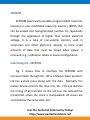
I2C (Inter Integrated Circuit)
The I2C (Inter-IC) bus is a bi-directional two-wire serial
bus that provides a communication link between integrated
circuits (ICs).I2C is a synchronous protocol that allows a
master device to initiate communication with a slave
device. Data is exchanged between these devices.
Join the Technical Community Today!
http://www.pantechsolutions.net
EEPROM
EEPROM (electrically erasable programmable read-only
memory) is user-modifiable read-only memory (ROM) that
can be erased and reprogrammed (written to) repeatedly
through the application of higher than normal electrical
voltage. It is a type of non-volatile memory used in
computers and other electronic devices to store small
amounts of data that must be saved when power is
removed, e.g., calibration tables or device configuration.
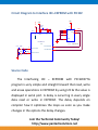
Interfacing I2C - EEPROM
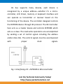
Fig. 1 shows how to interface the EEPROM with
microcontroller through I2C. I2C is a Master-Slave protocol.
I2C has a clock pulse along with the data. Normally, the
master device controls the clock line, SCL. This line dictates
the timing of all transfers on the I2C bus. No data will be
transferred unless the clock is manipulated. All slaves are
controlled by the same clock, SCL.
Join the Technical Community Today!
http://www.pantechsolutions.net
I2c bus supports many devices, each device is
recognized by a unique address—whether it’s a microcontroller, LCD Driver, memory or keyboard interface and
can operate as transmitter or receiver based on the
functioning of the device. The controller designed controls
the EEPROM device through I2C protocol. The I2C Controller
here acts as a master device and controls EEPROM which
acts as a slave. The read-write operations are accomplished
by sending a set of control signals including the address
and/or data bits. The control signals must be accompanied
with
proper
clock
signals.
Fig. 1 Interfacing I2C - EEPROM to Microcontroller
Join the Technical Community Today!
http://www.pantechsolutions.net
Interfacing I2C – EEPROM with PIC16F877A
We now want to Read, write and Erase EEPROM by
using I2C in PIC16F/18F Slicker Board. Wiring up an I2C
based EEPROM to the I2C port is relatively simple. The basic
operation of the I2C based EEPROM's is to send a
command, such as WRITE, followed by an address and the
data. In WRITE operation, the EEPROM to store the data.
In PIC16F/18F Slicker Kit, 2 nos. of EEPROM lines are
controlled by I2C Enabled drivers. I2C Lines serial clock of
CLK (PORTC.3), serial data of DATA (PORTC.4) connected to
the I2C based serial EEPROM IC. The EEPROM read & write
operations are done in PIC16F/18F Slicker Kit by using these
SCK & DATA I2C lines.
AT 24xx
Pin Assignment with PIC16F877A
I2C EEPROM
PIC16F/18F Lines
CLK
PORTC.3
DATA
PORTC.4
Serial EEPROM
AT24XX
PIC
EEPROM
Connections
*Turn ON TXD, RXD, SCL and MISO Pins
of CONFIG switch SW1.
*Connect Serial cable between USART
Section in the Board and PC.
Output: The string “I2C Test Program” will be displayed in Hyper- Terminal
Join the Technical Community Today!
http://www.pantechsolutions.net
VDD
VDD
VDD
VDD
8
12
31
1
2
3
VSS
VSS
1
MCLR/Vpp
U27
11
32
0.1uF
C58
7
4
PIC16F877A
RC3/SCK/SCL
22pF
22pF
13
Y 16
10 Mhz
14
SDA
SCL
5
SDA
6
SCL
PP
GND
U11
U14
C57
S0
S1
S2
VCC
MCLR
Circuit Diagram to Interface I2C–EEPROM with PIC16F
OSC1/CLKIN
RC4/SDI/SDA
18
I2C SEEPROM
23
OSC2/CLKOUT
C56
Source Code
The Interfacing I2C – EEPROM with PIC16F877A
program is very simple and straight forward that read, write
and erase operations in EEPROM by using I2C & the value is
displayed in serial port. A delay is occurring in every single
data read or write in EEPROM. The delay depends on
compiler how it optimizes the loops as soon as you make
changes in the options the delay changes.
Join the Technical Community Today!
http://www.pantechsolutions.net
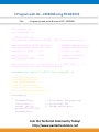
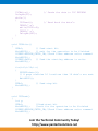
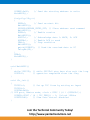
C Program with I2C – EEPROM using PIC16F877A
***************************************************************************************
Title
: Program to read, write & erase of I2C - EEPROM
***************************************************************************************
#include<pic.h>
#include<stdio.h>
__CONFIG(0x3f72);
//Select HS oscillator, BODEN, PWRT and disable others
#define EEPROM_CNTRL_IN 0xa0
#define EEPROM_CNTRL_OUT 0xa1
#define I2C_FREQ
100
// EEPROM address+write
// EEPROM address+read
// 100khz at 4Mhz
#define FOSC
#define BAUD_RATE
// 10Mhz==>10000Khz
// 9600 Baudrate
10000
9.6
#define BAUD_VAL
(char)(FOSC/ (16 * BAUD_RATE )) - 1;
//Calculation For 9600 Baudrate @10Mhz
unsigned char data[17]={"I2C Test Program"},i;
void
void
void
void
void
void
I2CWrite(void);
WaitMSSP(void);
I2CRead(void);
i2c_init(void);
serial_init(void);
DelayMs(unsigned int);
void main()
{
DelayMs(100);
i2c_init();
serial_init();
printf("\033[2J");
DelayMs(20);
// Give delay for power up
// Initialize I2C
// Setup serial port
Join the Technical Community Today!
http://www.pantechsolutions.net
I2CWrite();
DelayMs(50);
while(1)
{
I2CRead();
TXREG='\n';
while(TXIF==0);
TXREG='\r';
DelayMs(500);
}
// Sends the data to I2C EEPROM
// Read back the data’s
}
void I2CWrite()
{
SEN=1;
// Send start bit
WaitMSSP();
// wait for the operation to be finished
SSPBUF=EEPROM_CNTRL_IN;//Send Slave address write command
WaitMSSP();
SSPBUF=0x00;
// Send the starting address to write
WaitMSSP();
for(i=0;i<16;i++)
{
SSPBUF=data[i];
// A page contains 16 locations then 16 data’s are sent
WaitMSSP();
}
PEN=1;
// Send stop bit
WaitMSSP();
}
void I2CRead()
{
int y;
SEN=1;
//Send start bit
WaitMSSP();
//wait for the operation to be finished
SSPBUF=EEPROM_CNTRL_IN;//Send Slave address write command
WaitMSSP();
Join the Technical Community Today!
http://www.pantechsolutions.net
SSPBUF=0x00;
WaitMSSP();
// Send the starting address to write
for(y=0;y<16;y++)
{
RSEN=1;
// Send re-start bit
WaitMSSP();
SSPBUF=EEPROM_CNTRL_OUT; // Slave address read command
WaitMSSP();
RCEN=1;
// Enable receive
WaitMSSP();
ACKDT=1;
// Acknowledge data 1: NACK, 0: ACK
ACKEN=1;
// Enable ACK to send
PEN=1;
// Stop condition
WaitMSSP();
putch(SSPBUF); // Send the received data to PC
DelayMs(30);
}
PEN=1;
WaitMSSP();
}
void WaitMSSP()
{
while(!SSPIF); // while SSPIF=0 stay here else exit the loop
SSPIF=0;
// operation completed clear the flag
}
void i2c_init()
{
TRISC3=1;
// Set up I2C lines by setting as input
TRISC4=1;
SSPCON=0x28;
// SSP port, Master mode, clock = FOSC / (4 * (SSPADD+1))
SSPADD=(FOSC / (4 * I2C_FREQ)) - 1; //clock 100khz
SSPSTAT=80;
// Slew rate control disabled
}
Join the Technical Community Today!
http://www.pantechsolutions.net
void serial_init()
{
TRISC6=1;
TRISC7=1;
TXSTA=0x24;
SPBRG=BAUD_VAL;
RCSTA=0x90;
TXIF=1;
}
// Enable TX and RX pin for Serial port
//
//
//
//
Transmit Enable
9600 baud at 10 MHz
Usart Enable, Continus receive enable
Make TXREG register empty
void putch(unsigned char Data)
{
while(TXIF==0);
TXREG = Data;
}
// transmit data
void DelayMs(unsigned int Ms)
{
int delay_cnst;
while(Ms>0)
{
Ms--;
for(delay_cnst = 0;delay_cnst <220;delay_cnst++);
}
}
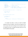
To compile the above C code you need the Mplab
software & Hi-Tech Compiler. They must be properly set up
and a project with correct settings must be created in order
to compile the code. To compile the above code, the C file
must be added to the project.
Join the Technical Community Today!
http://www.pantechsolutions.net
In Mplab, you want to develop or debug the project
without any hardware setup. You must compile the code for
generating HEX file. In debugging Mode, you want to check
the port output without PIC16F/18F Slicker Board.
The PICKIT2 software is used to download the hex file
into your microcontroller IC PIC16F877A through USB port.
Testing the I2C – EEPROM with PIC16F877A
Give +12V power supply to PIC16F/18F Slicker Board;
the EEPROM device is connected with the PIC16F/18F
Slicker Board. First check the entire EEPROM device fixed
properly. A serial cable is connected between the
microcontroller and PC. In PC, open the Hyper Terminal for
displaying the values from EEPROM through I2C.
The Read & Write operations are performed in
EEPROM with EEPROM address. When the EEPROM address
is correct, then only you can write, read, and erase data’s
correctly in EEPROM.
Join the Technical Community Today!
http://www.pantechsolutions.net
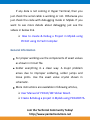
If any data is not coming in Hyper Terminal, then you
just check the serial cable is working or not. Otherwise you
just check the code with debugging mode in Mplab. If you
want to see more details about debugging just see the
videos in below link.
How to create & Debug a Project in Mplab using
PIC16F using Hi-Tech Compiler.
General Information
For proper working use the components of exact values
as shown in Circuit file.
Solder everything in a clean way. A major problem
arises due to improper soldering, solder jumps and
loose joints. Use the exact value crystal shown in
schematic.
More instructions are available in following articles,
User Manual of PIC16F/18F Slicker Board.
Create & Debug a project in Mplab using PIC16F877A.
Join the Technical Community Today!
http://www.pantechsolutions.net
Did you enjoy the read?
Pantech solutions creates information packed technical
documents like this one every month. And our website is a rich
and trusted resource used by a vibrant online community of
more than 1, 00,000 members from organization of all shapes
and sizes.
Join the Technical Community Today!
http://www.pantechsolutions.net
What do we sell?
Our products range from Various Microcontroller
development boards, DSP Boards, FPGA/CPLD boards,
Communication Kits, Power electronics, Basic electronics,
Robotics, Sensors, Electronic components and much more . Our
goal is to make finding the parts and information you need
easier and affordable so you can create awesome projects and
training from Basic to Cutting edge technology.
Join the Technical Community Today!
http://www.pantechsolutions.net