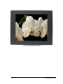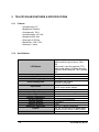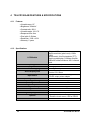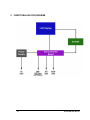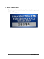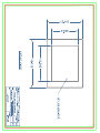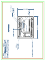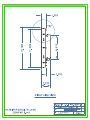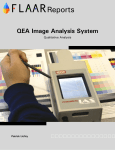
1
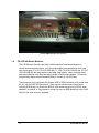
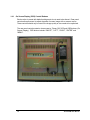
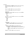
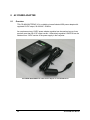
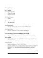
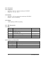
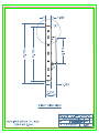
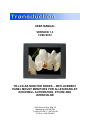
USER MANUAL VERSION 1.3 12/06/2012 TR-LCD-AB MONITOR SERIES – REPLACEMENT PANEL MOUNT MONITORS FOR ALLEN-BRADLEY ROCKWELL AUTOMATION, XYCOM AND INTERCOLOR 5155 Spectrum Way, Bldg. 23 Mississauga, ON L4W 5A1 T: (905) 625-1907, F: (905) 625-05 Toll Free: 1-800-268-0427 This page is left blank 4 TR-LCD-AB User Manual TABLE OF CONTENTS 1 15”, 17” & 19” PANEL MOUNT MONITORS .............................................................................. 8 1.1 Safety Precautions ...................................................................................................................................... 8 1.2 Overview ..................................................................................................................................................... 8 1.3 TR-LCD-AB Series Monitor Quick Start Guide ............................................................................................ 10 1.4 TR-LCD-AB Series Monitors ....................................................................................................................... 11 1.4.1 On Screen Display (OSD) Control Buttons ................................................................................................... 12 1.4.2 OSD Setup ................................................................................................................................................... 13 2 TR-LCD1500-AB FEATURES & SPECIFICATIONS................................................................ 18 2.1.1 2.1.2 3 Features ...................................................................................................................................................... 18 Specifications .............................................................................................................................................. 18 TR-LCD1700-AB FEATURES & SPECIFICATIONS................................................................ 19 3.1.1 3.1.2 4 Features ...................................................................................................................................................... 19 Specifications .............................................................................................................................................. 19 TR-LCD1900-AB FEATURES & SPECIFICATIONS................................................................ 20 4.1.1 4.1.2 Features ...................................................................................................................................................... 20 Specifications .............................................................................................................................................. 20 5 FUNCTIONAL BLOCK DIAGRAM ............................................................................................... 21 6 SERIAL NUMBER LABEL ............................................................................................................. 22 7 RESISTIVE TOUCH SCREEN ........................................................................................................ 23 7.1 Overview ................................................................................................................................................... 23 7.2 Specifications ............................................................................................................................................ 23 7.2.1 Mechanical .................................................................................................................................................. 23 7.3 Optical....................................................................................................................................................... 25 7.4 Reliability .................................................................................................................................................. 25 7.4.1 Charter Writing Operation (Iterated drawing in 20mm x 20mm squares) ................................................. 25 7.4.2 Rubber Stroke Operation ............................................................................................................................ 25 7.4.3 Shock Resistance ......................................................................................................................................... 25 5 TR-LCD-AB User Manual 7.5 Resistance to Chemicals ............................................................................................................................ 26 7.6 Electrical.................................................................................................................................................... 27 7.6.1 Electrical Discharge Protection ................................................................................................................... 27 7.6.2 Contact Bounce ........................................................................................................................................... 27 7.6.3 Open Circuit Resistance .............................................................................................................................. 27 7.6.4 Close Circuit Resistance............................................................................................................................... 27 7.6.5 Breakdown Voltage ..................................................................................................................................... 27 8 8.1 AC POWER ADAPTER .................................................................................................................. 28 Overview ................................................................................................................................................... 28 8.2 Specifications ............................................................................................................................................ 29 8.2.1 Electrical ...................................................................................................................................................... 29 8.2.2 Environment ................................................................................................................................................ 31 8.2.3 EMC Characteristics .................................................................................................................................... 31 8.2.4 Reliability ..................................................................................................................................................... 32 8.2.5 Mechanical .................................................................................................................................................. 32 9 MECHANICAL DRAWINGS .......................................................................................................... 33 9.1 TR-LCD1500-AB Drawings .......................................................................................................................... 34 9.2 TR-LCD1700-AB Drawings .......................................................................................................................... 39 9.3 TR-LCD1900-AB Drawings ..........................................................................................................................44 9.4 Panel Mount Monitor Clip .........................................................................................................................49 6 TR-LCD-AB User Manual Important Information The information in this document is subject to change without notice. All relevant issues have been considered in the preparation of this document. Should you notice an omission or any questionable item, please feel free to notify Transduction. Regardless of the foregoing statement, Transduction assumes no responsibility for any errors that may appear in this document or for results obtained by the user as a result of using this product. Copyright © 2012 Transduction. All rights reserved. This document is protected by copyright. No part of this document may be reproduced, copied, or translated in any form or means without prior written permission from Transduction. All other trademarks, brand, and product names are the property of their respective owners. Return policy Warranty is 5 years for the whole system from the date of purchase. Products returned for repair must be accompanied by a Return Material Authorization (RMA) number obtained from Transduction prior to return. The customer is responsible for any loss or damage caused by the carrier in transit. To obtain an RMA number, call us at 905-625-1907. We will need the following information: Return company address and contract Model name, model number, and serial number Description of the failure Mark the RMA number clearly on the outside of each box, include a failure report and return the product to: Transduction Inc. 23 – 5155 Spectrum Way Mississauga, ON L4W 5A1 Canada 7 TR-LCD-AB User Manual 1 15”, 17” & 19” PANEL MOUNT MONITORS 1.1 Safety Precautions When not used for extended periods of time, set your PC to DPMS. If using a screen saver, set it to the active screen mode. Do not use a damaged or loose plug. This may cause an electric shock or fire. Do not pull the plug out by the wire or touch the plug with wet hands. This may cause an electric shock or fire. Use only a properly grounded plug or receptacle. An improper ground may cause electric shock or equipment damage. Do not excessively bend the plug and wire or place heavy objects on them. This could cause damage and an electric shock or fire. Do not place the monitor face down. The CDT surface may be damaged. When cleaning, wipe with a slightly moistened, soft cloth. Do not spray any cleaner directly on to the monitor. Do not remove housing. No serviceable parts inside. Refer servicing to Transduction. 1.2 Overview TR-LCD1500-AB, TR-LCD1700-AB and TR-LCD1900-AB are industrial panel mount monitors designed to replace Allen-Bradley Rockwell-Automation, Xycom and Intercolor monitors that clients are using. These monitors have been manufactured under strict QA Standard CSA Z299.3 and are mechanically compatible with existing panel cut-outs including A-B type easy screw-on mounting clips and NEMA 4X type neoprene LCD panel mount hose proof gaskets. 8 TR-LCD-AB User Manual TR-LCD-AB Series Monitor Front View 9 TR-LCD-AB User Manual TR-LCD-AB Series Monitor Rear View 1.3 TR-LCD-AB Series Monitor Quick Start Guide To attach the TR-LCD-AB series monitor to your system, follow these instructions: 1. Turn off power to your computer. 2. Plug the power cord for the monitor into a nearby outlet. 3. Using the analog SVGA input on the video card, connect one end of SVGA connector cable into the video card. Connect other end of the cable to the SVGA input on the back of your monitor. 4. This is optional (DVI cable not provided). Using the DVI (digital) input on the video card, connect one end of the DVI cable into the video card and the other end to the DVI input on the back of your monitor. 5. For monitor configuration with USB touch screen. Connect one end of the USB cable to USB input on the back of your computer. Connect the other end of the USB cable to the USB input on the back of your monitor. 6. Turn on your computer and monitor. If your monitor displays an image, installation is complete. 10 TR-LCD-AB User Manual TR-LCD-AB Rear External Connectors 1.4 TR-LCD-AB Series Monitors TR-LCD-AB series monitors are highly reliable industrial monitors packaged in a custom enclosure made of steel. Only the most reliable components have been used such as no-glare 15” LCD (TR-LCD1500-AB), 17” LCD (TR-LCD1700-AB) and 19” LCD (TR-LCD1900-AB) that have stable crystal clear video display, video controller board with highly effective noise filter and highly reliable 12VDC power adapter. This results in high quality display with estimated reliability in excess of 150,000 hours. These monitors can be supplied with optional USB or RS232 resistive touch screen and 24, 48, 125 and 250V DC input power. Other options include various video inputs including RGB w/ Sync In Green and RGBVH with custom timing for any RS170 video standard. In addition, a “long distance” version for mono or RGB distance of up to 1000 feet from the video source is available. 11 TR-LCD-AB User Manual 1.4.1 On Screen Display (OSD) Control Buttons Each monitor is preset with default settings and do not need to be altered. Rear panel controls allow personnel to adjust elements of screen image with on-screen menus. These controls should only be used if the image quality or size needs to be optimized. The rear panel controls contains view access to “Power ON” LED and OSD buttons (On Screen Display). OSD buttons include “ON/OFF”, “LEFT”, “RIGHT”, “ENTER” and “MENU”. TR-LCD-AB Rear with OSD Control Buttons 12 TR-LCD-AB User Manual TR-LCD-AB OSD Control Buttons 1.4.2 OSD Setup 1.4.2.1 Overview The TR-LCD-AB features an on-chip OSD (On-Screen Display) controller that creates the OSD user interface menus and overlays them onto the output data stream. User can adjust the display conditions on the monitor using the OSD control buttons. After powering on, the monitor restores itself to the last known conditions saved in NonVolatile Random Access Memory (NVRAM). All parameters (Settings) are saved whenever user selects icon in OSD. Not making a selection within a defined time period causes the OSD menu to close. The LEFT and RIGHT keypad push buttons are used to scroll through items within the main menu. The selected item is highlighted. The MENU push button is used to open and close the OSD menu. The MENU push button is defined as Confirm or Enable button to activate the highlighted item. The ON/OFF push button enables user to perform LCD power-up sequence. 1.4.2.2 Main Menu Press MENU of OSD board to start Main Menu. There are five major icons in the Main menu: Image, Display, PIP, Sound (NOT APPLICABLE), and System. Use LEFT or RIGHT to select target icon and press ENTER to start adjustment. For example, when Image icon is highlighted, press ENTER and then use LEFT or RIGHT to select the sub-item. If sub-item Brightness is selected, press ENTER and then LEFT or RIGHT to adjust the brightness level. If setting is finished, press MENU back to Brightness subitem and press MENU again back to Image menu. New OSD parameters are saved in NVRAM after pressing MENU. Note: If changing the setting is finished, press MENU back to sub-item and press MENU again back to Image menu. New OSD parameters are saved in NVRAM after pressing MENU. 13 TR-LCD-AB User Manual 1.4.2.3 Image Brightness – Press LEFT or RIGHT to adjust the brightness of LCD backlight directly. This feature should work together with the inverter which provides PWM (Pulse Width Modulation) or DC Voltage control feature. BlackLevel – Press LEFT or RIGHT to adjust the black level. Contrast – Press LEFT or RIGHT to adjust contrast setting. Hue – Press LEFT or RIGHT to adjust video hue level (for video signal only). Saturation – Press LEFT or RIGHT to adjust video saturation (for video signal only). Color Auto color – Press ENTER to apply this function, and then press LEFT or RIGHT to select Yes to save or No to exit. - Yes - No Color temperature – Press ENTER to select color temperature. And press ENTER again to enable color depth adjustment. Press LEFT or RIGHT to adjust color depth for RGB. 9300K 7500K 6500K 5000K 4200K USER - Red - Green - Blue sRGB – Press ENTER to set standard color defined in MS Windows. Press LEFT or RIGHT to select On or Off to enable or disable sRGB. - On - Off 14 TR-LCD-AB User Manual 1.4.2.4 Display Auto Configuration – Press ENTER to automatically configure an optimal display setting. Then press LEFT or RIGHT to select Yes to save or No to exit. Yes No Phase – Press LEFT or RIGHT to adjust signal phase for RGB input. Clock – Press LEFT or RIGHT to adjust signal clock for RGB input. Display Control Display Image – Press LEFT or RIGHT to select image size. And press ENTER to Enable and Save the setting. Auto 1:1 Aspect Aspect Ratio – Press LEFT or RIGHT to select aspect ratio. And press ENTER to Enable and Save the setting. Auto >16x9 16x9 14x9 4x3 Display Position Horizontal – Press LEFT or RIGHT to adjust horizontal position of display. Vertical – Press LEFT or RIGHT to adjust vertical position of display. Zoom In/Out – Press LEFT or RIGHT to enable or disable the function. Zoom Position – This feature works only when Zoom Out function works. - Horizontal – Press LEFT or RIGHT to adjust horizontal position of zoom-out display. - Vertical – Press LEFT or RIGHT to adjust vertical position of zoom-out display. Sharpness – Press LEFT or RIGHT to adjust the sharpness level. 15 TR-LCD-AB User Manual 1.4.2.5 PIP PIP – Press LEFT or RIGHT to enable or disable the function. On Off PIP Input Select – Press LEFT or RIGHT to select PIP input port. VGA VGA2 DVI V-Port PIP Size – Press LEFT or RIGHT to select PIP size. Side Large Medium Small PIP Position – Press LEFT or RIGHT to set PIP position. Right-Top Right-Down Left-Top Left-Down PIP Color Controls BlackLevel – Press LEFT or RIGHT to adjust black level. Contrast – Press LEFT or RIGHT to adjust contrast level. Hue – Press LEFT or RIGHT to adjust video hue level (for video signal only). Saturation – Press LEFT or RIGHT to adjust video saturation (for video signal only). Blend – Press ENTER to enter blend slider, and use LEFT or RIGHT to adjust blend value 1.4.2.6 Sound - NOT APPLICABLE 16 TR-LCD-AB User Manual 1.4.2.7 System Input Select – Press LEFT or RIGHT to select main input port. VGA DVI S-Video Composite Components V-port (Optional) VGA2 (Optional) OSD Configuration OSD Timer – Press LEFT or RIGHT to decrease or increase the amount of time that elapses before the menu disappears. OSD Position - Horizontal – Press LEFT or RIGHT to adjust horizontal position of OSD screen. - Vertical – Press LEFT or RIGHT to adjust vertical position of OSD screen. OSD Zoom – Press ENTER to enable On or Off to expand OSD image or not. - On - Off Factory Reset – Press ENTER to enable factory reset, and previous setting stored in NVRAM will be lost. This feature helps users return back to original default setting in NVRAM, especially when users get problems when adjusting OSD features. Light Sensor – NOT APPLICABLE 17 TR-LCD-AB User Manual 2 TR-LCD1500-AB FEATURES & SPECIFICATIONS 2.1.1 Features 2.1.2 Viewable area: 15” Brightness: 600cd/m² Contrast ratio: 700:1 Viewable angle: V/H 140° Response time: 8ms Pixel pitch: 0.297mm Resolution: 1280 x 768 Warranty: 5 years Specifications LCD Module Input Signal Display Colours Maximum Viewing Angles Active Display Area Input Power Operating Temperature Operating Humidity Operating Altitude Storage Temperature Storage Humidity Storage Altitude Vibration & Shock Regulatory Approvals Options Model 18 Diagonal: 15” Native resolution (pixel count): 1024 x 768 Active matrix, thin film transistor (TFT) liquid crystal display (0.294mm dot pitch, 350cd/m² white luminance, 700:1 contrast ratio SVGA, DVI and optional RS170 RGBVH Analog input 16.2M Left/Right and Up/Down 140° Horizontal: 304.128mm Vertical: 228.096mm 60W, 90-264VAC, 50/60Hz regulated 12VDC output power adapter 0°C~50°C, 60°C for 2 hours 10%~90% non-condensing 0~10,000 ft -20°C~60°C 5%~50% non-condensing 0~30,000 ft 5/30G ESA FCC Class B compliance - 24, 48, 125 and 250V DC power input - Resistive touch screen, USB or RS232 TR-LCD1500-AB TR-LCD-AB User Manual 3 TR-LCD1700-AB FEATURES & SPECIFICATIONS 3.1.1 Features 3.1.2 Viewable area: 17” Brightness: 350cd/m² Contrast ratio: 1000:1 Viewable angle: V/H 165° Response time: 5ms Pixel pitch: 0.264mm Resolution: 1280 x 1024 Warranty: 5 years Specifications LCD Module Input Signal Display Colours Maximum Viewing Angles Active Display Area Input Power Operating Temperature Operating Humidity Operating Altitude Storage Temperature Storage Humidity Storage Altitude Vibration & Shock Regulatory Approvals Options Model 19 Diagonal: 17” Native resolution (pixel count): 1280 x 1024 Active matrix, thin film transistor (TFT) liquid crystal display (0.264mm dot pitch, 350cd/m² white luminance, 1000:1 contrast ratio SVGA, DVI and optional RS170 RGBVH Analog input 16.7M Left/Right and Up/Down 165° Horizontal: 337.92mm Vertical: 270.34mm 60W, 90-264VAC, 50/60Hz regulated 12VDC output power adapter 0°C~50°C, 60°C for hours 10%~90% non-condensing 0~10,000 ft -20°C~60°C 5%~50% non-condensing 0~30,000 ft 5/30G ESA FCC Class B compliance - 24, 48, 125 and 250V DC power input - Resistive touch screen, USB or RS232 TR-LCD1700-AB TR-LCD-AB User Manual 4 TR-LCD1900-AB FEATURES & SPECIFICATIONS 4.1.1 Features 4.1.2 Viewable area: 19” Brightness: 300cd/m² Contrast ratio: 800:1 Viewable angle: V/H 170° Response time: 8ms Pixel pitch: 0.294mm Resolution: 1280 x 1024 Warranty: 5 years Specifications LCD Module Input Signal Display Colours Maximum Viewing Angles Active Display Area Input Power Operating Temperature Operating Humidity Operating Altitude Storage Temperature Storage Humidity Storage Altitude Vibration & Shock Regulatory Approvals Options Model 20 Diagonal: 19” Native resolution (pixel count): 1280 x 1024 Active matrix, thin film transistor (TFT) liquid crystal display (0.294mm dot pitch, 300cd/m² white luminance, 800:1 contrast ratio SVGA, DVI and optional RS170 RGBVH Analog input 16.7M Left/Right and Up/Down 170° Horizontal: 376.32mm Vertical: 301.06mm 60W, 90-264VAC, 50/60Hz regulated 12VDC output power adapter 0°C~50°C, 60°C for hours 10%~90% non-condensing 0~10,000 ft -20°C~60°C 5%~50% non-condensing 0~30,000 ft 5/30G ESA FCC Class B compliance - 24, 48, 125 and 250V DC power input - Resistive touch screen, USB or RS232 TR-LCD1900-AB TR-LCD-AB User Manual 5 FUNCTIONAL BLOCK DIAGRAM 21 TR-LCD-AB User Manual 6 SERIAL NUMBER LABEL Each serial number label consists of 5 numbers. There is 1 label that is applied to each monitor. 1. Rear of LCD display panel 22 TR-LCD-AB User Manual 7 RESISTIVE TOUCH SCREEN 7.1 Overview 5‐wire resistive touchscreen is composed of glass (bottom layer) coated with transparentconductive material (ITO) film (top layer) and top and bottom layers touch screeneach other, and electric analog X, Y signals are transmitted to the touch controller. The analog signals transmitted from the panel are converted to digital signals by the A/D converter of the controller and then transmitted to the control driver of each operating system. The software driver is optimized to operate the touch panel for each operating system by receiving digital signals converted from the controller. 7.2 Specifications 7.2.1 Mechanical 7.2.1.1 Features - Analog resistive type touch screen with 5-wire technology. - Input mode: finger, gloved finger or stylus pen. - Input method Pen: 110g (polyacetal) Stylus: 110g (silicon rubber) - Structure PET (ITO Film) Anti-Glare film, 188m ±15%(T), 3H Clear film, 188m ±15%(T), 3H Glass ITO Glass 1.8, 2.9mm ±10%(T) - Controller: Serial (RS232) and USB 23 TR-LCD-AB User Manual 7.2.1.2 Linearity Accuracy - Standard deviation of error is less than 2% error on most displays. Detected touch coordinates, after being mathematically fitted to actual touch coordinate patterns shall not have a standard deviation of error in excess of 1.5% in either axis using Test software as the data collection and calculation tool. Criteria Direction [X] : 1.5% or less Direction [Y] : 1.5% or less 7.2.1.3 Touch Activation Force When activated by a “Standard Finger” the activating force is typically less than 110g. 7.2.1.4 Hard Coat Pencil Hardness Meets pencil hardness 3H. 7.2.1.5 Surface Durability Surface durability is tested as follows: As shown above the touch screen is mounted on measuring equipment and then stroked 10,000 times in a straight line in one location of the ITO film hard coated on panel by stylus pen with pressure. The pen speed is 100±15mm per second with 250gf of force of pressure. Abrasion test will be reported well if there is no abrasion shown up with the above procedure without failure. 24 TR-LCD-AB User Manual 7.3 Optical - Light Transmittance (Total Transmittance): 81% (550nm wavelength, according to JISK7105) 7.4 Reliability 7.4.1 Charter Writing Operation (Iterated drawing in 20mm x 20mm squares) Writing 10,000,000 characters must satisfy requirements in section 7.2.1.2 and 7.6. Hits must be made in the following manner at any point within effective area. 1. Testing equipment: Pen plotter 2. Testing load: 250gf 3. Press speed: 2 hits/second 4. Tip probe: silicon rubber R8.0, hardness shore 12 7.4.2 Rubber Stroke Operation 30,000,000 strokes with a piece of rubber must satisfy requirements in paragraph 7.2.1.2 and 7.6. Hits must be made in the following manner at any point within effective area. 1. Testing equipment: Pen plotter 2. Testing load: 250gf 3. Press speed: 2 hits/second 4. Tip probe: silicon rubber R8.0, hardness shore of 12 7.4.3 Shock Resistance Requirement in section 7.2.1.2 and 7.6 must be satisfied. No breakage when R10mm steel ball is dropped from 15cm height at one time on the touch panel supported with the display module. 25 TR-LCD-AB User Manual 7.5 Resistance to Chemicals Industrial chemicals: acetone, methylene chloride, methyl ethyl ketone, isopropyl alcohol, hexane, turpentine, mineral spirits, unleaded gasoline, diesel fuel, motor oil, transmission fluid and antifreeze. Food-service chemicals: vinegar, coffee, tea, grease, cooking oil, salt, plus most commercial cleaners including ammonia-based glass cleaner and laundry detergent. 26 Property Acetone Isopropanol Toluene Boiling Water Curling Test Specification Change in /sq. < 3% Change in /sq. < 3% Change in /sq. < 3% Change in /sq. < 3% < 20mm Humidity Resistance ±8% Flexibility > 13mm Test Method 10min. @ 25°C 10min. @ 25°C 10min. @ 25°C 10min. 450mm x 450mm 150°C for 30min., measured at corners Change in /sq. 24hrs. @ 60°C 95%RH Diameter TR-LCD-AB User Manual 7.6 Electrical 7.6.1 Electrical Discharge Protection Meets 24kV air/13kV contact discharges. 7.6.2 Contact Bounce Beginning of the touch pulse shall not exceed 15msec. 7.6.3 Open Circuit Resistance The controller is designed to distinguish resistance values less than 20k ohms to filter false or near touches. 7.6.4 Close Circuit Resistance Shall be less than 3,000 ohms when measured between the signals contact (pin 3) to any drive contact (pin 1,2,4, or 5) on the connector when the touch screen is actuated anywhere within the touch active area with a standard finger exerting a force of 10 to 20 ounces. 7.6.5 Breakdown Voltage The touch screen, with no force applied to the active surface, shall be capable of withstanding a difference of potential 50VDC between the signal contact (pin 3) and any drive contact (pin 1,2,4, or 5) on the connector for a period of 5min. 27 TR-LCD-AB User Manual 8 AC POWER ADAPTER 8.1 Overview TR-LCD-AB-ADAPTERAC-V3 is a reliable universal isolated 60W power adapter with regulated 12VDC output, 90-264VAC, 50/60Hz. As a replacement any 12VDC power adapter regulated can be used as long as it can produce more than 5A of DC output current. Alternatively regulated 12VDC/5A can be obtained from 12VDC section of the power supply in the computer. TR-LCD-AB-ADAPTERAC-V3 12VDC Power Adapter for TR-LCD-AB Series 28 TR-LCD-AB User Manual 8.2 Specifications 8.2.1 Electrical 8.2.1.1 Input Voltage (AC~) - 100-240VAC nominal. 90-264VAC maximum. 8.2.1.2 Input Frequency - 47-63Hz 8.2.1.3 Input Current - 1.5A max. @ 90VAC 8.2.1.4 Inrush Current - 100A max. cold-start @ 25°C, DC output full load and 230VAC input. 8.2.1.5 Hold-Up Time - 8msec. min. at DC output full load and 100VAC 50/60Hz input. 8.2.1.6 Input Wattage at Output No Load/Minimum Load Condition - Less than 0.75W at output no load and 240VAC input voltage frequency condition. 8.2.1.7 Efficiency - 75% min. at DC output full load and 100VAC input voltage range, including DC output cable voltage drop loss. 8.2.1.8 Safety Test - Leakage current less than 0.75mA at 254VAC 50/60Hz Hi-Pot Test: 3000VAC 10mA, 2 sec. between primary and secondary circuit and chassis. Insulation: 500VDC, 2 sec. between primary and secondary circuit, IR shall 20M. Grounding: AC 30A, 2 sec. between input safety ground and SELV output GND, GR0.1. 29 TR-LCD-AB User Manual 8.2.1.9 Output Voltage and Current (DC) VOUT Range 12.0V 11.40 – 12.60V 0 – 5.0A IOUT Range 8.2.1.10 Ripple and Noise - Low frequency ripple (<100KHz) 150mVpp Total composite ripple and noise < 150mVpp tested by DC loading side parallel with 10uF/EC and 0.1uF/Ceramic capacitors, measured band-width with DC-20MHz. 8.2.1.11 Over-Shoot and Under-Shoot - Less than 5% of nominal voltage. 8.2.1.12 Protection - SCP: for short circuit protection and with auto-recovery function. OVP: over-voltage protection, 18VDC 100mS max. at DC output full load and with autorecovery function. 8.2.1.13 LED Indication - Green light for nominal operation and blank for SCP and OVP mode. 8.2.1.14 Start Up Rise Time - The output voltage should rise from 0V and settle within regulation in less than 3sec. from applying 100VAC for start up and rise time input voltage condition. 8.2.1.15 Output Voltage Temperature Coefficient - Less than 0.2%/°C 8.2.1.16 Output Transient Response DC Output 12.0 12.0 12.0 30 I1(A) 0.00 1.25 2.50 I2(A) 1.25 2.50 5.00 dV max (V) ±1.0V ±1.0V ±1.0V Tset-max 10msec. 10msec. 10msec. dI/dt 50mA/usec. 50mA/usec. 50mA/usec. TR-LCD-AB User Manual 8.2.2 Environment 8.2.2.1 Temperature - Operating: 0 - 40°C (32 - 104°F) for nominal input 100-240VAC. Storage: -40 - 70°C (-40 - 158°F). 8.2.2.2 Humidity - Operating: 5 – 90% non-condensing for nominal input 100-240VAC. Storage: 5 – 95% non-condensing. 8.2.2.3 Altitude - 10,000ft operating, 40,000ft non-operating. 8.2.3 EMC Characteristics 8.2.3.1 EMS Test Item ESD ESD RS EFT SURGE CS DIPS Test Specification Contact: 8KV Air: 15KV Fr: 26MHz -1.0GHz, Field Strength: 3V/M 2KV on AC power line 1KV (L.N) and 2KV (L.N-PE) 3V/M 0% 250 cycle, 40% 5 cycle, 70% 0.5 cycle IEC Standards 61000-4-2 61000-4-2 61000-4-3 61000-4-4 61000-4-5 61000-4-6 61000-4-11 8.2.3.2 Conducted and Radiated EMI Referring Standard CISPR EN55022 C-TICK FCC VCCI BSMI 31 Pub 22, class B Meet Part 15, class B Class B Meet TR-LCD-AB User Manual 8.2.4 Reliability 8.2.4.1 MTBF - 60,000 hours at 25°C. 8.2.4.2 Temperature Rise - Less than 40°C at nominal 100-240VAC input. 8.2.4.3 Burn-In - 100% Burn-In with 80 – 100% load at 35 - 50°C. 8.2.4.4 Vibration Test - Non-operation vibration with shipping container shall be 5G peak 7 – 250Hz. 5G peak 50 – 500Hz after 30min. test no abnormality found. Operation vibration shall be 0.5G 5 – 250Hz 3-axes after 30min. test no abnormality. 8.2.4.5 Drop Test - 8.2.5 - Test height 75cm, no abnormality noted. Mechanical Plastic case with UL PC+ABS GE C2950 material, colour Black. Physical Size: 110mm (L) x 63.00mm (W) x 31.50mm (H) (4.33” (L) x 2.48” (W) x 1.24” (H)). Output cable with UL1185, 18AWG wires and DC jack plug with two direct pins. Weight: 330g (0.73lb). 32 TR-LCD-AB User Manual 9 MECHANICAL DRAWINGS This page is left blank 33 TR-LCD-AB User Manual 9.1 TR-LCD1500-AB Drawings This page is left blank 34 TR-LCD-AB User Manual 9.2 TR-LCD1700-AB Drawings This page is left blank 39 TR-LCD-AB User Manual 9.3 TR-LCD1900-AB Drawings This page is left blank 44 TR-LCD-AB User Manual 9.4 Panel Mount Monitor Clip This page is left blank 49 TR-LCD-AB User Manual