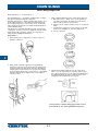
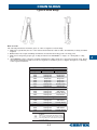
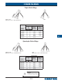
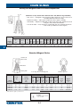
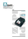
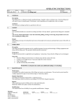
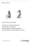
1
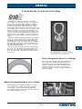
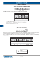
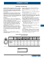
CHAIN SLINGS Acco, Chain & Lifting Products Division Recommended Chain Sling Use Follow these Recommendations for Safer Chain Sling Use 1. Visually examine the sling before each use. Look for stretched, gouged, bent or damaged links and components, including hooks, with opened throats, cracks or distortion. If damaged, remove from service. 6. Slings should not be shortened with knots, bolts or other makeshift devices. 7. Protect chain with padding when lifting sharp edged loads. 2. Know the load — determine the weight, center of gravity, angle of lift and select the proper size and type of sling. 8. Lift and lower loads smoothly, do not jerk. 6 3. Never overload the sling — check the working load limit on the identification tag. Always consider the effect of Angle of Lift — the tension on each leg of the sling is increased as the angle of lift, from horizontal, decreases. Use the charts in this catalog or in the Acco Chain Sling User’s Manual for this purpose. 9. Hands and fingers should not be placed between the sling and load while sling is being tightened around the load. When lifted, the load should not be pushed or guided by employee’s hands directly on the load. 4. Do not point load hooks — load should bear on the bowl of hook. 10. Do not expose A8A alloy chain or slings to temperatures above 500°F. (See Table next page.) 11. Protect chain slings from corrosion during storage. 5. Make sure chain is not twisted, knotted or kinked before lifting the load. 12. Store slings properly on an A-Frame. 6-1 CHAIN SLINGS Chain Sling Inspection Daily Inspection — as shownAcco, in No. 1Chain & Lifting Products Division Recommendations — should be conducted by a competent person designated by the employer. Periodic Inspection — OSHA specifies that all alloy steel chain slings shall have a thorough periodic inspection, by a competent person, at least once every 12 months. These inspections must be recorded and maintained for each individual sling. The inspection schedule should be based on frequency of sling use, severity of service conditions, nature of lifts being made and experience gained on service life of slings used in similar circumstances. Inspection — 1. Clean chain prior to inspection, to more easily see damage or defects. 3. Make a link-by-link inspection of the chain slings for: a. Excessive wear — If the wear on any portion of any link exceeds the allowable wear shown in Table of Wear remove from service. b. Twisted, bent, gouged, nicked, worn or elongated links. c. Cracks in the weld area of any portion of the link. Transverse markings are the most dangerous. d. Severe corrosion. 6 2. Hang chain vertically if practical, for preliminary inspection. Measure reach accurately (bearing point of master link to bearing point of hook). Check this length against reach shown on tag. If present length is greater than that shown on tag, there is a possibility that the sling has been subjected to overloading or excessive wear. 4. Check master links and hooks for all of the above faults — hooks especially for excessive throat opening. Slings showing any of the faults described above should immediately be removed from service and returned to the manufacturer for repair. Certex offers a chain sling inspection service performed by our own qualified inspectors. 6-2 CHAIN SLINGS Types of Chain Slings Acco, Chain & Lifting Products Division How to Order The following information should be given on orders or inquiries for chain slings. 1. SIZE: This is specified by the size of the material from which the chain is made, determined by working load limit required. 2. REACH: This is the length, including attachments, measured from bearing point to bearing point. 3. TYPE: Select and specify proper type of sling from list shown. EXAMPLES: S—single, O—oblong link, S—sling hook. 4. ATTACHMENTS: Unless otherwise specified standard master links and hooks as given herein will be used. When other than standard master links or hooks are required, we should be given a complete description or a drawing of the requested substitute. Type SG SOS SOG SGS SGG SSS SOF CO DOS DOG DOF DOP TOS TOG TOF QOS QOG QOF Single Chain Slings Attachments One End Opposite End Plain Grab Hook Oblong Link Single Hook Oblong Link Grab Hook Grab Hook Sling Hook Grab Hook Grab Hook Sling Hook Sling Hook Oblong Link Foundry Hook Oblong Link Oblong Link Double Chain Slings Oblong Link Sling Hooks Oblong Link Grab Hooks Oblong Link Foundry Hooks Oblong Link Plate Hooks Triple Chain Slings Oblong Link Sling Hooks Oblong Link Grab Hooks Oblong Link Foundry Hooks Quadruple Chain Slings Oblong Link Single Hooks Oblong Link Grab Hooks Oblong Link Foundry Hooks WARNING Failure to read, understand and follow the instructions, working load limits and specifications in this and other publications could result in serious injury or property damage. 6-3 6 CHAIN SLINGS & Lifting Products Division Single Chain Slings Acco, Chain Plain End CO SOS** or SOSH SOG SOF Choke Hook Note: Not limited to Single Chain Sling Applications Specifications CERTEX Cat. Ref. No. CX-06-0132 CX-06-0133 CX-06-0134 CX-06-0135 CX-06-0136 CX-06-0137 CX-06-0138 CX-06-0139 6 Size of Chain In. 9/32 3/8 1/2 5/8 3/4 7/8 1 1-1/4 mm 7 10 13 16 20 22 26 32 Grade 80 Working Load Limits* Lbs. at 90° Grade 100 Working Load Limits* Lbs. at 90° 3,500 7,100 12,000 18,100 28,300 34,200 47,700 72,300 4,300 8,800 15,000 22,600 35,300 42,700 _ _ SG CERTEX Cat. Ref. No. CX06-0117 CX06-0118 CX06-0119 CX06-0120 CX06-0121 CX06-0122 CX06-0123 Double Chain Slings DOSH or DOS DOF Specifications CERTEX Cat. Ref. No. CX-06-0132 CX-06-0133 CX-06-0134 CX-06-0135 CX-06-0136 CX-06-0137 CX-06-0138 CX-06-0139 Size of Chain In. 9/32 3/8 1/2 5/8 3/4 7/8 1 1-1/4 mm 7 10 13 16 20 22 26 32 Grade 80 Working Load Limits* Lbs. at 60° Grade 100 Working Load Limits* Lbs. at 60° 6,100 12,300 20,800 31,300 49,000 59,200 82,600 125,200 7,400 15,200 26,000 39,100 61,100 74,000 _ _ * WARNING Working Load Limits should not be exceeded. Do not point load hooks. 6-4 CERTEX Cat. Ref. No. CX06-0117 CX06-0118 CX06-0119 CX06-0120 CX06-0121 CX06-0122 CX06-0123 CHAIN SLINGS Acco, Chain & Lifting Products Division Triple Chain Slings TOSH or TOS TOG (same as above with Grab Hooks) TOF Specifications CERTEX Cat. Ref. No. CX-06-0147 CX-06-0148 CX-06-0149 CX-06-0150 CX-06-0151 CX-06-0152 CX-06-0153 CX-06-0154 Size of Chain In. 9/32 3/8 1/2 5/8 3/4 7/8 1 1-1/4 mm 7 10 13 16 20 22 26 32 Grade 80 Working Load Limits* Lbs. at 60° Grade 100 Working Load Limits* Lbs. at 60° 9,100 18,400 31,200 47,000 73,500 88,900 123,900 187,000 11,200 22,900 39,000 58,700 91,700 110,900 _ _ CERTEX Cat. Ref. No. CX06-0117 CX06-0118 CX06-0119 CX06-0120 CX06-0121 CX06-0122 CX06-0123 6 Quadruple Chain Slings QOSH or QOS QOG (same as above with Grab Hooks) QOF QOG (same as above with Grab Hooks) Specifications CERTEX Cat. Ref. No. CX-06-0147 CX-06-0148 CX-06-0149 CX-06-0150 CX-06-0151 CX-06-0152 CX-06-0153 CX-06-0154 Size of Chain In. 9/32 3/8 1/2 5/8 3/4 7/8 1 1-1/4 mm 7 10 13 16 20 22 26 32 Grade 80 Working Load Limits* Lbs. at 60° Grade 100 Working Load Limits* Lbs. at 60° 9,100 18,400 31,200 47,000 73,500 88,900 123,900 187,000 11,200 22,900 39,000 58,700 91,700 110,900 _ _ * WARNING Working Load Limits should not be exceeded. Do not point load hooks. 6-5 CERTEX Cat. Ref. No. CX06-0117 CX06-0118 CX06-0119 CX06-0120 CX06-0121 CX06-0122 CX06-0123 CHAIN SLINGS Steady-Lift Magnet Chains (3-Point Suspension) Eliminates Costly Down Time With Lift After Lift, Built-In Dependability • Ease of Use — Designed so bail stands up while chain rests on floor, there is no wrestling with the bail for hook-up. • Balanced Loading — Three point suspension offers superior stability. • Wearability — Engineered and built for increased service life, with heat treated bail, pins, alloy chain and end links. • Less Down Time — Easy inspection, replaceable pins, legs and bail mean more time on the job and fewer off-site repairs. Specifications A CERTEX Cat. Ref. No. 6 Size of Chain No. of Links *W.L.L. Lbs. B Mtl. Dia. C D Yoke Wth. Yoke Lgh. Vert. Reach E End Link Wth. F End Link Lgh. G End Link Dia. Comp. Assy. Wt. Lbs. Yoke Wt. Lbs. Chain Leg. Wt. Lbs. Pin Wt. Lbs. Ea. Magnet Diameter In. CX06-0261 1 100,000 5 2-1/4 7 12 3' -7" 2-5/8 7 1-1/4 220 110 31 5.0 up to 60 CX06-0262 1-1/4 150,000† 7 2-1/2 7 12 4' -7" 2-3/4 7 1-1/2 350 155 60 5.5 60 and over Standard Magnet Chains Standard ‘D’ Master Link Main Chain Oblong Link Pear Shape Master Link Optional Handles Optional Specifications Master Link Chain Working Size Oblong Link Load Limit* A Dia. B Inside C Inside A Dia. B Inside C Inside 5 Link Magnet Mtl. In. Width In. Length In. Mtl. In. Width In. Length In. Reach In. Diameter In. 1-3/4 2 2-1/8 2-1/4 2-1/2 6 6 6 6-1/2 6-1/2 10-1/2 10-1/2 10-1/2 11-1/4 12-3/4 3/4 7/8 1 1-1/4 1-1/2 2-1/8 2-1/8 2-1/8 2-3/4 2-3/4 6 6 6 7 7 32-1/2 35 36 40 45-1/2 up to 40/ up to 45 up to 48 up to 60 60 and over CERTEX Cat. Ref. No. In. mm Lbs. at 60° CX06-0263 CX06-0264 CX06-0265 CX06-0266 CX06-0267 5/8 3/4 7/8 1 1-1/4 16 20 22 26 32 47,000 73,500 88,900 123,900 187,800 † Values shown are grade 63, embossed ‘AS’ * WARNING Working Load Limits should not be exceeded. 6-6 SPECTRUM 10® ALLOY CHAIN • • • • • • Heat Treated. 25% stronger than Grade 80 Alloy Chain. Permanently embossed with CG (Crosby Group) and 10 (Grade). Finish - Black rust preventative coating. Proof Tested at 2 times the Working Load Limit with certification. Columbus McKinnon Oblong Master Corporation Link Standard container - fiber drum. CHAIN SLING FITTINGS Type & size of chain sling on which used Single Double Triple Quad type type type type S&C D T Q Link size (inches) Working load limit CERTEX (lbs.)* † Cat. Ref. No. Diameter material A Inside width B Inside length C 3,600 CX06-0268 13/32 1 1/2 3 7/32 Grade 100 Alloy Chain Recommended for overhead lifting applications 6,100 12,300 Feet Per 20,800 Drum 31,300 500 49,000 500 500 73,500 300 88,900 200 125,200 100 100 187,800 Chain Size CX06-0269 1/2 2 1/2 Working CX06-0270 Material 3/4 Load2 3/4 Limit3 1/2 CX06-0271Size 1 (in.) (lbs.)* CX06-0272.276 1 1/4 4 3/8 4300 CX06-0273.343 1 1/2 57005 1/4 8800 6 CX06-0274.394 1 3/4 .512 15000 CX06-0275.630 2 7 22600 CX06-0276.787 2 1/4 35300 8 CX06-0277.866 2 3/4 42700 9 Gr. 100 Drum (in.) (mm) Stock No. 9/32 (1/4) 7 273710 5/16 8 273729 3/8 10 273738 1/2 13 273747 5/8 16 273756 3/4 20 273858 7/8 22 273867 1 26 273876 75 1.02 59700 † Working load limit of master link only. * Proof loaded at 2 times Working Load Limit. Ultimate Load is 4 times the Working Load Limit. 7/32 — 9/32 9/32 7/32 Maximum Maximum 3/8 3/8 Length 9/32 Inside 1/2Width or 5/8 1/2100 Links 3/8 (in.) (in.) 3/4 5/8 1/2 .42 90 7/8 3/4 100 5/8 .49 1.58 7/8 125 3/4 .77 164 1 1/4 1 7/8 .90 202 — 1 1/4 252 1 .98 1.08 — — 2771 1/4 5 Maximum 5 1/2 Inside Length 7 (in.) 8 3/4 .87 10 1/2 1.01 1.23 12 1.57 14 1.93 16 2.52 2.77 16 3.28 1.28 328 Weight each (lbs.) — .33 7/32 .8 Weight 9/32Per 2.1 100 3/8 Feet 4.6 (lbs.) 1/2 75 9.2 5/8113 15.7 3/4148 24.5 249 7/8378 37.3 1 590 54.0 1 1/4740 84.8 1010 Oblong Master Link Sub-Assembly** For triple and quad branch chain slings Oblong master link size (inches) A B C ® A-1337 • • • • • • • CERTEX Cat. Ref. No. Master coupling link size (inches) D E F Weight (lbs.) 1/2and Grade 5 CX06-0278 11/32 5/8 1 1/8 1.0 Suitable for use with both1/2 Grade2 80 100 chain. 2 3/4 1/2 CX06-0279 15/32 7/8 1 9/16 2.6 Individually Proof Tested3/4 at 2-1/2 times5Working Load Limit with certification. 1 3 1/2 7 CX06-0280 21/32 1 1/4 2 1/4 6.1 Locking system that provides for simple assembly and disassembly - no special tools needed. 1 1/4 4 3/8 8 3/4 CX06-0281 29/32 1 3/4 3 1/8 13.3 25% stronger than Grade1 80. 1/2 5 1/4 10 1/2 CX06-0282 1 5/32 2 1/4 4 24.3 Meets ASTM A-952-02 standards for Grade fittings. 1 9/32 1 3/4 6 12 100 chain CX06-0283 2 3/8 4 3/8 36.1 Forged Alloy Steel - Quenched and 2 7 Tempered. 14 CX06-0284 1 17/32 2 3/4 5 1/4 57.4 2 1/4 8 rated. 16 CX06-0285 1 25/32 3 6 83.9 Sizes 9/32 through 1 inch are fatique 2 3/4 9 16 CX06-0286 2 1/32 3 1/2 7 129.7 HA chain (in.) 7/32 9/32 3/8 1/2 5/8 3/4 7/8 1 1 1/4 ** Consisting of oblong master link and two welded master coupling links. LOK-A-LOY® 10 Alloy Connecting Link Chain Size (in.) (mm) 9/32 (1/4) 7 5/16 3/8 1/2 5/8 3/4 7/8 1 1-1/4 8 10 13 16 20 22 25 32 A-1337 Weight Stock Pkg. Each No. Qty. (lbs.) 1015104 60 .26 1015113 1015122 1015136 1015145 1015154 1015163 1015172 1015181 50 40 12 10 1 1 1 1 .35 .75 1.60 2.68 5.00 7.50 11.03 20.38 Working Dimensions Load (in.) Limit (lbs.)* A B C D 4300 load limit .38of master 1.94 .81 † Working link only.1.90 5700 8800 15000 22600 35300 42700 59700 90400 .37 .48 .68 .81 .93 1.06 1.22 1.50 2.35 2.70 3.45 4.13 4.62 5.46 5.98 7.43 2.07 2.47 3.31 3.90 4.62 5.46 6.13 7.59 *Ultimate Load is 4 times the Working Load Limit. For Grade 6 LOK-A-LOY®, see page 246. * WARNING • Do not exceed working load limit. • Use only alloy chain and attachments for overhead lifting. 6-7 .99 1.12 1.44 1.72 2.03 2.27 2.44 3.07 E F .69 .72 .90 1.12 1.35 1.62 2.00 2.25 2.56 .57 .64 .78 .97 1.14 1.28 1.49 1.76 2.23 6 CHAIN SLING FITTINGS Columbus McKinnon Corporation Clevlok® Sling Hook Without Latch** 6 CERTEX Cat. Ref. No. CX06-0346 CX06-0347 CX06-0348 CX06-0349 CX06-0350 (in.) (mm) Working load limit (lbs.)* 9/32 3/8 1/2 5/8 3/4 7 10 13 16 20 3,500 7,100 12,000 18,100 28,300 Chain size D E G H I K L M N O P Weight each (lbs.) 3.500 4.343 5.500 6.281 7.827 1.500 1.875 2.250 2.625 3.000 5.156 6.672 8.000 9.687 11.688 0.328 0.453 0.593 0.750 0.875 0.734 0.953 1.172 1.438 1.688 1.594 2.187 2.562 2.281 3.437 0.357 0.507 0.625 0.750 0.906 3.437 4.468 5.265 6.078 7.344 1.187 1.437 1.781 2.031 2.500 1.203 1.453 1.938 2.375 2.828 1.051 1.281 1.656 2.188 2.563 0.64 1.91 4.33 5.20 11.40 Dimensions (inches) ** Latches available either as an option or in kit form. User must determine whether latch is required on the hook. Clevlok® Sling Hook With Latch CERTEX Cat. Ref. No. CX06-0351 CX06-0352 CX06-0353 CX06-0354 CX06-0355 (in.) (mm) Working load limit (lbs.)* 9/32 3/8 1/2 5/8 3/4 7 10 13 16 20 3,500 7,100 12,000 18,100 28,300 Chain size D G H I L M O P R Weight each (lbs.) 3.500 4.343 5.500 6.281 7.827 5.156 6.672 8.000 9.687 11.688 0.328 0.453 0.593 0.750 0.875 0.734 0.953 1.172 1.438 1.688 0.357 0.507 0.625 0.750 0.906 3.437 4.468 5.265 6.078 7.344 1.203 1.453 1.938 2.375 2.828 1.051 1.281 1.656 2.188 2.563 1.062 1.312 1.562 1.750 2.187 0.80 2.03 4.50 6.50 11.80 Dimensions (inches) * WARNING • Do not exceed working load limit. • Use only alloy chain and attachments for overhead lifting. 6-8 CHAIN SLING FITTINGS Columbus McKinnon Corporation Cradle Grab® Hook CERTEX Cat. Ref. No. (in.) (mm) Working load limit (lbs.)* CX06-0365 CX06-0366 CX06-0367 CX06-0368 CX06-0369 CX06-0370 CX06-0371 CX06-0372 CX06-0373 7/32 9/32 3/8 1/2 5/8 3/4 7/8 1 1 1/4 5.5 7 10 13 16 20 22 26 32 2,100 3,500 7,100 12,000 18,100 28,300 34,200 47,700 72,300 Chain size Dimensions (inches) B D E G H I K L M N O P Weight each (lbs.) — 1.62 2.06 2.63 3.06 3.50 3.88 4.31 5.31 3.31 3.50 4.34 5.50 6.34 7.83 8.59 9.59 11.56 1.44 1.50 1.88 2.25 2.63 3.00 3.38 4.00 4.66 4.30 5.25 6.64 8.16 9.66 11.38 12.72 14.23 17.00 0.38 0.44 0.56 0.75 0.88 1.00 1.09 1.22 1.50 0.78 0.73 0.95 1.17 1.44 1.69 1.94 2.14 2.62 1.25 1.59 2.19 2.56 2.63 3.44 3.88 4.25 4.64 0.75 0.75 0.94 1.13 1.31 1.50 1.69 1.88 2.31 3.06 3.75 4.78 5.69 6.50 7.81 8.75 9.88 11.50 1.25 1.19 1.44 1.78 2.03 2.50 2.78 3.13 3.88 1.00 1.20 1.45 1.94 2.38 2.83 3.22 3.55 4.25 0.86 1.05 1.28 1.66 2.19 2.51 2.84 3.09 3.89 0.7 1.1 1.9 4.5 7.3 11.4 18.1 22.6 36.0 † Not cradle type. Sling Hook** Without Latch CERTEX Cat. Ref. No. (in.) (mm) Working load limit (lbs.)* CX06-0356 CX06-0357 CX06-0358 CX06-0359 CX06-0360 CX06-0361 CX06-0362 CX06-0363 CX06-0364 7/32 9/32 3/8 1/2 5/8 3/4 7/8 1 1 1/4† 5.5 7 10 13 16 20 22 26 32 2,100 3,500 7,100 12,000 18,100 28,300 34,200 47,700 72,300 Chain size Dimensions (inches) B D E G H I K L M P Weight each (lbs.) 1.19 1.38 1.78 2.28 2.75 3.19 3.75 4.31 5.38 1.75 1.81 2.63 3.34 4.08 4.88 5.69 7.00 8.25 0.36 0.36 0.45 0.59 0.75 0.88 1.00 1.19 1.50 2.69 3.44 4.67 5.86 7.13 8.25 9.63 12.44 15.56 0.38 0.38 0.50 0.63 0.75 0.88 1.00 1.22 1.56 1.19 1.19 1.75 1.88 2.25 2.88 3.00 3.88 2.50 0.96 0.99 1.48 1.98 2.63 3.06 3.75 4.31 5.50 0.63 0.63 0.78 1.03 1.25 1.44 1.75 1.88 2.25 1.63 2.36 3.11 3.94 4.78 5.50 6.50 8.09 10.50 .70 .70 1.06 1.30 1.59 1.88 2.12 3.12 3.50 0.35 0.40 1.06 2.26 4.36 6.70 10.40 20.90 40.00 ** Available from stock with/without latch. Replacement latch kits are also available. User must determine if latch is required on the hook. * WARNING • Do not exceed working load limit. • Use only alloy chain and attachments for overhead lifting. 6-9 6 CHAIN SLING FITTINGS Columbus McKinnon Corporation Sling Hook With Latch CERTEX Cat. Ref. No. (in.) (mm) Working load limit (lbs.)* CX06-0374 CX06-0375 CX06-0376 CX06-0377 CX06-0378 CX06-0379 CX06-0380 CX06-0381 CX06-0382 7/32 9/32 3/8 1/2 5/8 3/4 7/8 1 1 1/4 5.5 7 10 13 16 20 22 26 32 2,100 3,500 7,100 12,000 18,100 28,300 34,200 47,700 72,300 Chain size 6 Dimensions (inches) B D E G H I K L M N O P R Weight each (lbs.) — 1.63 2.06 2.63 3.06 3.50 3.88 4.31 5.31 3.31 3.50 4.34 5.50 6.34 7.83 8.59 9.59 11.28 1.44 1.50 1.88 2.25 2.63 3.00 3.38 4.00 4.66 4.30 5.25 6.64 8.16 9.66 11.38 12.72 14.23 17.00 0.38 0.44 0.56 0.75 0.88 1.00 1.09 1.22 1.50 0.78 0.73 0.95 1.17 1.44 1.69 1.94 2.14 2.62 1.25 1.59 2.19 2.56 2.63 3.44 3.88 4.25 4.64 0.75 0.75 0.94 1.13 1.31 1.50 1.69 1.88 2.31 3.06 3.75 4.78 5.69 6.50 7.81 8.75 9.88 11.50 1.25 1.19 1.44 1.78 2.03 2.50 2.78 3.13 3.88 1.00 1.20 1.45 1.94 2.38 2.83 3.22 3.55 4.25 0.86 1.05 1.28 1.66 2.19 2.51 2.84 3.09 3.89 1.11 1.06 1.31 1.56 1.75 2.19 2.38 2.78 3.41 0.7 1.1 1.9 4.5 7.3 11.4 18.1 22.6 36.0 Foundry Hook Foundry Hook—Proof Tested (in.) (mm) Working load limit (lbs.)* 9/32 3/8 1/2 5/8 3/4 7/8 1 1 1/4 7 10 13 16 20 22 26 32 3,500 7,100 12,000 18,100 28,300 34,200 47,700 72,300 Chain size CERTEX Cat. Ref. No. CX06-0383 CX06-0384 CX06-0385 CX06-0386 CX06-0387 CX06-0388 CX06-0389 CX06-0390 Dimensions (inches) B D E G H I K L M N O R Weight each (lbs.) 1.56 2.00 2.50 3.00 3.50 4.00 4.50 5.13 4.75 5.75 6.75 7.81 9.13 10.14 11.13 12.84 2.50 3.00 3.50 4.00 4.50 5.00 5.50 6.00 6.45 7.88 9.38 10.97 12.81 14.23 15.84 18.03 0.47 0.63 0.75 0.88 1.00 1.13 1.25 1.38 1.00 1.27 1.50 1.81 2.20 2.25 2.59 3.17 1.56 1.88 2.22 2.63 3.00 3.38 3.75 4.25 0.63 0.75 1.00 1.25 1.50 1.75 2.13 2.38 4.75 5.75 6.88 8.06 9.25 10.38 11.56 12.88 2.50 3.00 3.50 4.00 4.50 5.00 5.50 6.00 1.23 1.50 1.75 2.03 2.56 2.78 3.03 3.81 0.25 0.31 0.37 0.43 0.50 0.56 0.62 0.75 2.4 4.5 7.1 11.6 20.0 26.0 36.8 58.4 * WARNING • Do not exceed working load limit. • Use only alloy chain and attachments for overhead lifting. 6-10 CHAIN SLING FITTINGS Gunnebo-Johnson Corp Alloy BK Self Locking Hooks (Eye Type) Latch closes automatically under load. Hook will not open under load. The release trigger will only operate when hook is unloaded. All three hooks are equipped with Stainless Steel springs. Heat number indentification allows full product traceability. BK CERTEX Cat. Ref. No. GunneboJohnson Code Chain Size CX06-0537 BK-6-10 CX06-0538 Dimensions (Inches) Weight Each (Lbs) Grade Working Load Limit *(Lbs) L B E F G H 7/32 100 2,700 4.3 1.1 .87 .39 .55 .75 .9 BK-7/8-10 9/32 100 4,300 5.4 1.4 .99 .43 .67 .91 1.6 CX06-0539 BK-10-10 3/8 100 8,800 6.6 1.7 1.3 .51 .98 1.1 3.3 CX06-0540 BK-13-10 1/2 100 15,000 8.2 2.1 1.6 .63 1.1 1.5 5.9 CX06-0541 BK-16-10 5/8 100 22,600 10.0 2.5 2.0 .79 1.5 1.9 12.0 CX06-0542 BK-18/20-8 3/4 100 35,300 12.6 3.1 2.8 .95 1.9 2.4 25.0 CX06-0543 BK-22-8 7/8 80 34,200 12.6 3.1 2.8 .95 1.9 2.4 25.0 CX06-0544 BK-26-8 1 80 47,700 13.6 3.9 3.1 1.0 2.0 2.7 32.0 CX06-0545 BK-28-8 1 1/8 80 55,100 15.8 4.7 3.5 1.1 2.4 3.2 48.0 6 * Design factor 4:1 Proof tested and certified. Self Locking OBK With Grip Latch (Eye Type) Latch is protected and will act as a gauge to signal an gauge to signal an unsafe bent hook or latch. Grip latch locks into point of hook. All three hooks are equipped with Stainless Steel springs. Heat number identification allows full product traceability. OBK CERTEX Cat. Ref. No. GunneboJohnson Code Chain Size Grade Working Load Limit *(Lbs) CX06-0546 OBK-7/8-10 CX06-0547 Dimensions (Inches) L B E F G H Weight Each (Lbs) 9/32 100 4,300 5.1 1.3 .99 .39 .67 .79 1.5 OBK-10-10 3/8 100 8,800 6.4 1.7 1.3 .49 .83 .97 2.7 CX06-0548 OBK-13-10 1/2 100 15,000 7.7 2.0 1.6 .59 1.0 1.2 4.5 CX06-0549 OBK-16-10 5/8 100 22,600 9.3 2.4 2.0 .75 1.2 1.5 7.7 CX06-0550 OBK-18/20-8 3/4 80 28,300 11.5 2.8 2.3 1.1 1.4 1.9 10.2 * Design factor 4:1 Proof tested and certified. WARNING Never exceed published working load limit 6-11 CHAIN SLING FITTINGS Gunnebo-Johnson Corp Self Locking BKL With Bronze Bushings (Swivel Eye Type) Bushing allows hook to swivel when load is applied. The release trigger will only operate when hook is unloaded. Latch closes automatically under load. Hook will not open under load. Heat number identification allows full product traceability. GunneboJohnson Code CX06-0551 CX06-0552 CX06-0553 Chain Size L B C E F G H Weight Each (Lbs) BKL-6-10 7/32 2,700 5.9 1.1 .91 1.3 .43 .55 .75 1.4 BKL-7/8-10 9/32 4,300 7.2 1.4 1.1 1.4 .47 .67 .91 2.4 BKL-10-10 3/8 8,800 8.6 1.7 1.5 1.7 .59 .99 1.1 4.4 CX06-0554 BKL-13-10 1/2 15,000 10.9 2.1 1.7 1.9 .75 1.1 1.5 8.4 CX06-0555 BKL-16-10 5/8 22,600 13.2 2.5 2.3 2.4 .87 1.5 1.9 15.0 CERTEX Cat. Ref. No. 6 BKL Working Load Limit *(Lbs) Dimensions (Inches) * Design factor 4:1 Proof tested and certified. Self Locking BKLK With Ball Bearings (Swivel Eye Type) Ball bearing allows the hook to swivel under load. The release trigger will only operate when hook is unloaded. Latch closes automatically under load. Hook will not open under load. Heat number identification allows full product traceability. All three hooks are equipped with Stainless Steel springs. BKLK CERTEX Cat. Ref. No. GunneboJohnson Code Chain Size Working Load Limit *(Lbs) Dimensions (Inches) L B C E F G H Weight Each (Lbs) CX06-0556 BKLK-6-10 7/32 2,700 5.8 1.1 .87 1.3 .43 .55 .75 1.5 CX06-0557 BKLK-7/8-10 9/32 4,300 7.2 1.4 1.1 1.4 .47 .67 .91 2.4 CX06-0558 BKLK-10-10 3/8 8,800 8.5 1.7 1.3 1.6 .59 .99 1.1 4.2 CX06-0559 BKLK-13-10 1/2 15,000 10.9 2.1 1.6 1.9 .75 1.1 1.5 8.4 CX06-0560 BKLK-16-10 5/8 22,600 13.2 2.5 2.0 2.4 .87 1.5 1.9 15.9 * Design factor 4:1 Proof tested and certified. WARNING Never exceed published working load limit 6-12 CHAIN SLING FITTINGS Self Locking (Clevis Type) Alloy BK Safety Hooks Gunnebo-Johnson Corp Clevis prevents hook to chain size mismatch. Latch closes automatically under load. Hook will not open under load. Release trigger will only operate when hook is unloaded. Heat number identification allows full product traceability. GunneboJohnson Code Chain Size Working Load Limit *(Lbs) L B G H Weight Each (Lbs) CX06-0561 BKG-7-10 9/32 4,300 4.7 1.4 .67 .91 1.7 CX06-0562 BKG-10-10 3/8 8,800 5.6 1.7 .99 1.1 3.3 CX06-0563 BKG-13-10 1/2 15,000 7.1 2.1 1.1 1.5 6.2 CX06-0564 BKG-16-10 5/8 22,600 8.5 2.5 1.5 1.9 11.0 CERTEX Cat. Ref. No. Dimensions (Inches) * Design factor 4:1 Proof tested and certified. Self Locking With Grip Latch (Clevis Type) Clevis prevents hook to chain size mismatch. Release trigger will only operate when hook is unloaded. Latch closes automatically under load. Hook will not open under load. Latch is protected and will act as a guage to signal unsafe bent hook or latch. Heat number identification allows full product traceability. CERTEX Cat. Ref. No. GunneboJohnson Code Chain Size Working Load Limit *(Lbs) Dimensions (Inches) L B G H Weight Each (Lbs) CX06-0565 GBK-7-10 9/32 4,300 4.4 1.3 .67 .79 1.3 CX06-0566 GBK-10-10 3/8 8,800 5.4 1.7 .83 .97 2.4 CX06-0567 GBK-13-10 1/2 15,000 6.6 2.0 1.0 1.2 4.4 * Design factor 4:1 Proof tested and certified WARNING Never exceed published working load limit 6-13 6 CHAIN SLING FITTINGS Gunnebo-Johnson Corp Alloy Specialty Products Alloy Weld-On Hooks The spring loaded latch is the strongest available. Heat number identification allows full product traceability. Welding instructions supplied with each hook. UKN 6 CERTEX Cat. Ref. No. GunneboJohnson Code Working Load Limit *(Tons) Dimensions (Inches) B C G H K L S A Weight Each (Lbs) CX06-0568 UKN-1** 1.0 .79 2.8 .67 .99 .99 3.7 .24 .16 1.3 CX06-0569 UKN-3 3.0 1.2 4.1 .91 1.3 1.4 5.2 .39 .24 2.9 CX06-0570 UKN-4 4.0 1.1 4.5 1.1 1.5 1.7 5.5 .43 .28 4.2 CX06-0571 UKN-5 5.0 1.3 5.2 1.2 1.9 1.8 6.5 .47 .32 6.4 CX06-0572 UKN-8 8.0 1.3 5.2 1.6 2.0 2.0 6.8 .51 .35 7.7 CX06-0573 UKN-10 10.0 1.9 6.7 1.7 2.3 2.2 8.7 .55 .35 14.1 CX06-0574 UKN-15 15.0 2.1 7.4 2.0 2.6 2.4 9.4 .59 .47 19.4 * Design factor 5:1 Proof tested and certified. Baseplate of hook is 1024C steel (use electrode AWS/ASTM E7018-1, ISO E51 5 B120 20H). Welding is to be done by a qualified welder. Hook latch is alloy. ** Welding plate on UKN 1 is slightly curved. WARNING Never exceed published working load limit 6-14 GRAB IQ A Totally New Way To Fabricate Chain Slings GrabiQ is an exciting new family of alloy chain sling components. Instead of the old “one component does one job” fitting, GrabiQ combines in a single component up to three separate functions. Figure 1 features a GrabiQ Master Grab, which serves as the master link, connecting link for two legs of chain, and shortening hooks for each leg, all in one fitting. Using traditional fittings to construct the same sling would require 7 top-of-the-sling components, instead of just one. Some of the new GrabiQ fittings are equally well suited for use as top assembly connectors or hooks at the bottom of a sling, adding even more flexibility for riggers. While the specific Working Load Limits vary, depending on size, slings fabricated from grade 100 chain and fittings are about 25% stronger than their grade 80 counterparts. Converting from grade 80 to GrabiQ will especially benefit users who can make use of the additional WLL without the expense of purchasing larger chain and fittings. The percentage of strength increase varies depending on the size. The Working Load Limit (WLL) gain for 3/8” is about 24 percent, while the WLL for 7/32” is more than 30 percent. All other sizes fall somewhere in between. 6 Fig. 1. The GrabiQ Master Grab combines a master link, master link connectors for two legs of chain, and two shortening hooks into a single fitting. The shortening hook can also be used to create loop legs. Fewer Components Means Less Weight Most of the time, GrabiQ slings will be lighter than their grade 80 counterparts. Fewer components means less weight. Also, because grade 100 has a lifting capacity that is usually 25% highter than its grade 80 counterpart, the ratio of strength-toweight is greater, offering additional weight savings with GrabiQ. Fig. 2.Each GrabiQ component is clearly marked with the number 10, designating it as Grade 100. Reduced Components Means Less Clutter Because GrabiQ often reduces the number of components required to assemble a chain sling, rigging is easier. Figure 3 shows a three-leg fully adjustable chain sling with all three legs shortened. The sling still has only three fittings at the top. Fig. 3. “A three-leg, fully adjustable sling.” 6-15 GRAB IQ More Flexibility in Chain Sling Uses When each GrabiQ leg is furnished with a chain pocket, the chain sling can be used for a much wider variety of loads, often reducing the amount of rigging required on site. The chain pocket can be used to either shorten a leg or create a leg loop. Some fittings are equally well suited for use at the top or bottom of a chain sling. For example, the GrabiQ C-Grab can be used as a top-of-the-sling connector or as picuted in Figure 4, at the bottom of the sling as an adjustable sliding choker. Fig. 4. “A GrabiQ C-Grab used at the bottom of the sling as an adjustable sliding choker.” Chain Sling Inspections Are Easier Inspecting chain slings is easier and faster because fewer components must be examined for wear or damage. 6 Fig. 5.Only 3 top-of-the-sling GrabiQ components are needed to fabricate a 4-leg, fully adjustable sling. Quality Standards: Gunnebo Grade 100 GrabiQ™ alloy steel chain and chain sling components are manufactured and tested in accordance with ASTM A973, A952, and A907 material standards. GrabiQ™ chain and components meet or exceed the safety standards as prescribed by ASME B30.9 & B30.10, and OSHA alloy steel chain sling regulations. All chain and every single component is proof-loaded to 2.5 time the Working Load Limit. The Swedish plants manufacturing GrabiQ™ products certified to ISO 9001 / ISO 9002 Quality Standards. Gunnebo’s quality management covers all aspects of production from raw material to delivered product. Full Test Certification is supplied on request. Fig. 6. Traditional fabrication requires 15 fittings. 6-16 CARBON CHAIN Products Division Chain Definitions The Low Carbon chains and attachments shown in this catalog are designed for general purpose applications and are not to be used for lifting or hoisting purposes or where chain failure is likely to cause injury to persons or damage to property. For lifting or hoisting applications, chain and attachments should be used. Instructions and Cautions Governing the Purchase and Use of Chain Working Load Limit: The “working load limit” is the maximum load in pounds which at any time or under any condition should ever be applied to chain or a sling component, even when chain is new and in the same condition it was when it left the factory, and when the load is evenly applied in direct tension to a straight length of chain. The following factors or abuses will lessen the load that the chain assembly will withstand and should be avoided: • Tip loading of hooks • Twisting of the chain Acco, Chain & Lifting • Disfigurement • Deterioration of chain or component by wear, usage or corrosion. • Jerking or the sudden impact of a load multiplies the stress on the chain very rapidly. • Use other than that for which the chain or component was intended. Caution: Chain and component assemblies should be rated according to the working load limit of the weakest component. Instructions Regarding Attachments: Care should be taken to select attachments of the same type, grade, size and working load limit as the chain. Follow recommended attachment procedure for best results. Misuse or abuse of chain and attachments may result in serious personal injury. All dimensions shown are nominal and all weights are approximate. See individual pages for working load limits WARNING Failure to read, understand and follow these instructions and working load limits may cause serious physical injury and property damage. 6-17 6 CARBON CHAIN Chain Assemblies Grade 70 Transport Tiedown Chain Assemblies have Grade 70 Clevis Grab Hook each end. Packed 25 per drum. Grade 70 Transport Tiedown Chain Assembly Size 5/16 x 20 ft. 5/16 x 25 ft. 3/8 x 20 ft. Wt. Each Lbs. Working Load Limit Lbs.*† CERTEX Cat. Ref. No. 22 30 31 4,700 4,700 6,600 CX06-0714 CX06-0715 CX06-0718 Other lengths available upon request. † The values for working load limits shown here shall be used only for calculating the number of chain tiedown assemblies required to secure an article in compliance with Department of Transportation Regulations 393,102(b). 6 Acco, Chain & Lifting Products Division Winch Line Tail Chain Winch Line Tail Chain is a flexible attachment for use on the end of wire rope. Primarily intended for use on truck and tractor winch lines. Length specified is exclusive of hook. Use the same size chains as wire rope. The hook is drop forged alloy steel and heat treated for extra durability. The hook is designed to prevent wearing of the wire rope. Winch Line Tail Chain Trade Size Inches Length Each In. Excluding Hook Wt. Each Lbs. CERTEX Cat. Ref. No. 1/2 5/8 3/4 7/8 1 18 18 18 24 24 7 10 13 24 27 CX06-0725 CX06-0726 — — — Working Load Limit Lbs.* 9,200 14,000 19,750 — — CERTEX Cat. Ref. No. — — CX06-0728 CX06-0729 CX06-0730 * WARNING Working Load Limit must not be exceeded. Not to be used for lifting or hoisting applications. 6-18 Working Load Limit Lbs.* — — 28,300 34,300 38,750 CARBON CHAIN Definitions and Warnings Columbus McKinnon Corporation Columbus McKinnon Corporation assumes no responsibility for the use or misapplication of any of its products. Products are provided with the express understanding that the purchaser and/or user are thoroughly familiar with the correct application and proper use. The following warnings and definitions are provided as an aid to understanding. The chains listed on the pages in this price list exceed the specifications of the National Association of Chain Manufacturers for the specific types of chain involved. However, none of these chains are made from alloy steel and should not be used for overhead lifting purposes. CM Chain produces an alloy chain known as Herc-Alloy 800 chain that is designed for overhead lifting. Definitions Working Load Limit — Refers to the maximum load (rated capacity) in pounds that shall be applied in direct tension to a straight length of chain or attachment. The working load limit shall not be exceeded. Proof Test (or Manufacturing Test Force) — Refers to a load in pounds which an attachment or chain (or both) has withstood during a test in which an increasing tension is applied to an attachment or straight length of chain. This is typically accomplished as part of the manufacturing or testing process. Minimum Break Load — Refers to a load in pounds as applied to an attachment or chain at the time it left the factory that has been found by representative testing to break the item under test of increasing force as applied by a standard testing machine. This a manufacturing test and such data is not intended for service or design purposes. Warnings Never exceed the “working load limit” of chain or attachments, even when the item is new and the load is uniformly applied. Before use, always inspect chain and attachments for kinking, twisting, knotting, and visible defects such as distortion or damage. Do not jerk load. Pick up slowly and apply a steady pull. Protect items from corrosion. Any product will break if abused or overused. Use only alloy chain attachments (Grade 80) for overhead lifting purposes, never any other chain. The terms “working load limit,” “proof test,” and “minimum break load” contain no implication of what load an attachment or chain will withstand, if any, if the factors noted in the Definitions are changed. The “working load limit” should not be exceeded, even when an attachment or chain is new and the load is uniformly applied. The manufacturer does not accept any liability for damages with result from an attachment or chain being used in excess of the working load limit. Any changes in these factors could lessen the load the chain will hold. For example: Acceleration in the rate of application, which could cause dangerous overloading. Variation in the angle of the load. As the angle or incli nation decreases, the working load capacity of a sling will decrease accordingly. Twisting, knotting and kinking. A purpose other than that for which the chain was intended. Where attachments, such as hooks or rings are desired for use with chain in substaining loads, care should be taken to select attachments of the type, grade, and size recommended for use with corresponding alloy chain with which such attachments are used. 6 Grade 30 Proof Coil Chain Chain Specifications GRADE 30 PROOF COIL CHAIN Width Maximum Length, 100 Links Inches Weight per 100 ft. In Pounds Working* Load Limit In Pounds 0.41 .48 .50 .62 .82 99 104 114 128 158 33 63 98 144 278 750 1,250 1,900 2,650 4,500 1.01 1.13 1.51 194 220 286 422 606 1,069 6,900 9,750 13,950 Nominal Inside Link Dimensions, Inches Material Size Trade Size In Inches Inches Decimal Length 3/16 1/4 5/16 3/8 1/2 13/64 17/64 21/64 25/64 17/32 .202 .265 .327 .390 .531 0.96 1.01 1.11 1.24 1.51 5/8 3/4 1 21/32 25/32 1 1/32 .656 .781 1.031 1.88 2.13 2.77 Dimensions and weights are approximate and subject to variations. * WARNING: Working Load Limit is not to be exceeded. This chain/accessory is not for overhead lifting. 6-19 CARBON CHAIN Grade 43 High Test Chain Chain Specifications Grade 43 High Test Chain Nominal Inside Link Dimensions, Inches CX06-0731 CX06-0732 CX06-0733 CX06-0734 CX06-0735 Inches 9/32 21/64 25/64 17/32 21/32 Decimal .281 .327 .390 .531 .656 Length 1.01 1.11 1.24 1.51 1.88 Width .48 .50 .62 .82 1.01 CX06-0736 CX06-0737 CX06-0738 3/4 7/8 1 25/32 29/32 1 1/32 .781 .875 1.000 2.13 2.52 2.77 1.13 1.38 1.51 CERTEX Cat. Ref. No. 6 Material Size Trade Size In Inches 1/4 5/16 3/8 1/2 5/8 Maximum Length, 100 Links Inches Weight per 100 ft. In Pounds Working* Load Limit In Pounds 104 114 128 156 194 71 98 144 278 422 2,600 3,900 5,400 9,200 11,500 220 260 286 606 769 1,069 16,200 22,500 26,500 Maximum Length, 100 Links, Inches Weight per 100 ft. In Pounds Working* Load Limit In Pounds 87 102 119 134 149 74 100 156 204 259 3,150 4,700 6,600 8,750 11,300 Dimensions and weights are approximate and subject to variations. Grade 70 Binding Chain Chain Specifications Grade 70 Binding Chain CERTEX Cat. Ref. No. Trade Size In Inches CX06-0739 CX06-0740 CX06-0741 CX06-0742 CX06-0743 1/4 5/16 3/8 7/16 1/2 Material Size Inches 9/32 11/32 13/32 15/32 17/32 Decimal .281 .327 .406 .468 .531 Nominal Inside Link Dimensions, Inches Length .84 .99 1.15 1.30 1.45 Width .48 .47 .54 .62 .73 Dimensions and weights are approximate and subject to variations. * WARNING: Working Load Limit is not to be exceeded. This chain/accessory is not for overhead lifting. 6-20 CARBON CHAIN ATTACHMENTS Chain & Lifting Products Division Drop Forged Steel and Heat Treated Connecting Links Drop forged. For connection of attachments to chain. Links are provided with interlocking lugs and rivets. For permanent connections, the rivets must be peened into the counter sunk holes. Use with chain of equal or lower working load limit. Connecting Links Packaged Link Size Inches Working Load Limit Lbs.* Wt. Per Ctn. Lbs. Pcs. Per Ctn. CERTEX Cat. Ref. No. CERTEX Cat. Ref. No. 3/16 1/4 5/16 3/8 7/16 1/2 800 1,325 1,950 2,750 3,625 4,750 2/3 2/3 1 2 3 4 20 10 10 10 10 10 CX06-0853 CX06-0854 CX06-0855 CX06-0856 CX06-0857 CX06-0858 CX06-0859 CX06-0860 CX06-0861 CX06-0862 — CX06-0863 * WARNING Working load limit must not be exceeded. Not to be used for lifting or hoisting applications. 6-21 6 CARBON CHAIN ATTACHMENTS Double Clevis (Mid-Link) Columbus McKinnon Corporation APPLICATIONS: Used as a temporary or permanent link with proof coil or high test chain. DESCRIPTION: Drop forged, heat-treated, carbon steel, zinc-plated. PACKING: Display pack. For Chain Size Inches Carton CERTEX Cat. Ref. No. Columbus McKinnon Code No. UPC Code Display pack Clevis Opening Inches Pin Diameter Inches Reach Inches Weight Display Pack Pounds Working Load Limit* Pounds 1/4 & 5/16 CX06-0864 M605 28926 30 7/16 3/8 1 3/16 10 3,900 3/8 CX06-0865 M606 28936 30 1/2 7/16 1 3/8 14 5,400 7/16 & 1/2 CX06-0866 M608 28941 10 5/8 9/16 1 3/4 11 9,200 6 Quick Link APPLICATIONS: Used as a repair link, connecting link or attaching device. DESCRIPTION: Zinc-plated NOT heat-treated. Use only with chain or equal or lower Working Load Limit. PACKING: 3/16”, 1/4” and 5/16” sizes, packed 20 per carton, 3/8” and 1/2” sizes, packed 10 per carton. Carton For Chain Size Inches CERTEX Cat. Ref. No. Columbus McKinnon Code No. 3/16 CX06-0867 D81001 39751 20 1 1/2 1/4 CX06-0868 D81101 39755 20 1 3/4 5/16 CX06-0869 D81201 39760 20 2 5/16 3/8 3/8 17 1,760 3/8 CX06-0870 D81301 39765 10 2 7/16 7/16 7/16 23 2,220 1/2 CX06-0871 D81501 39770 10 3 3/16 19/32 19/32 51 3,300 UPC Code Display pack Clevis Opening Inches Reach Inches Weight Per 100 Pieces Pounds Working Load Limit* Pounds 1/2 1/4 4 1/2 660 9/16 9/32 8 880 Pin Diameter Inches * WARNING Working load limit must not be exceeded. Not to be used for lifting or hoisting applications. 6-22 CARBON CHAIN ATTACHMENTS Columbus McKinnon Corporation Repair Link APPLICATIONS: A temporary repair link also used to couple light attachments. DESCRIPTION: A mild steel, available with bright, hot galvanized, or zinc-plated finishes. PACKING: 100 per carton in 1/8” by 3/4” and 3/16” by 1” sizes, 50 per carton in the 7/32” by 1 1/4” through 3/8” by 2” sizes. 25 per carton in the 1/2” by 2 1/2” size. Trade Size Inches Zinc Plated Carton Bright Carton CERTEX Cat. Ref. No. Columbus McKinnon Code No. UPC Code CERTEX Cat. Ref. No. Columbus McKinnon Code No. Pieces per Carton Inside Length Inches Inside Width Inches Weight per 100 Pieces Pounds Working Load Limit* Pounds 175 UPC Code 1/8 x 3/4 — — — CX06-0883 653612 29251 100 3/4 1/4 1 1/8 3/16 x 1 CX06-0872 653180 29186 CX06-0884 653618 29256 100 1 1/2 3 1/2 225 7/32 x 1 1/4 CX06-0873 653211 29191 CX06-0885 653621 29261 50 1 1/4 1/2 5 1/2 450 1/4 x 1 1/4 CX06-0874 653251 29196 CX06-0886 653625 29266 50 1 1/4 1/2 7 1/2 400 1/4 x 1 1/2 CX06-0875 653253 29206 CX06-0887 653626 29276 50 1 1/2 1/2 8 1/3 400 1/4 x 2 CX06-0876 653255 29211 CX06-0888 653627 29281 50 2 5/8 10 1/2 400 9/32 x 1 1/4 CX06-0877 653281 29201 CX06-0889 653628 29271 50 1 1/4 1/2 9 3/4 375 5/16 x 1 1/2 CX06-0878 653312 29216 CX06-0890 653631 29286 50 1 1/2 3/4 14 1/2 675 5/16 x 2 CX06-0879 653315 29221 CX06-0891 653632 29291 50 2 3/4 17 1/3 625 3/8 x 1 5/8 CX06-0880 653373 29226 CX06-0892 653633 29296 50 1 5/8 3/4 23 1,050 3/6 x 2 CX06-0881 653375 29231 CX06-0893 653638 29301 50 2 3/4 24 1,000 1/2 x 2 1/2 CX06-0882 653506 29236 CX06-0894 653650 29306 25 2 1/2 1 54 1,525 Cold Shut APPLICATIONS: As temporary repair link, use one size larger than Proof coil chain (Grade 30) with which it is to be used. Also used to couple light attachments. DESCRIPTION: Low carbon steel, self-colored or zinc-plated finish. PACKAGING: 1/4” thru 5/8” zinc-plated, packed 10 per carton. All other bulk. Trade Size Inches Zinc-Plated Bulk (Ea.) CERTEX Cat. Ref. No. Columbus McKinnon Code No. Self-Colored Carton (10) UPC Code CERTEX Cat. Ref. No. Columbus McKinnon Code No. Inside Length Inches Inside Width Inches Weight per 100 Pieces Pounds Working Load Limit* Pounds UPC Code 3/16 CX06-0895 50091 29060 — — — 15/16 5/16 3 525 1/4 CX06-0896 50191 29062 CX06-0902 673104 34175 1 3/8 6 925 5/16 CX06-0897 50291 29067 CX06-0903 673105 34176 1 3/16 7/16 10 1,450 3/8 CX06-0898 50391 29072 CX06-0904 673106 34177 1 5/16 1/2 18 2,110 7/16 CX06-0899 50491 29077 CX06-0905 673107 34178 1 1/2 9/16 26 2,850 1/2 CX06-0900 50591 29082 CX06-0906 673108 34179 1 9/16 3/4 38 3,750 5/8 CX06-0901 50691 29087 CX06-0907 673110 34180 2 1/8 7/8 78 5,850 * WARNING Working Load Limit is not to be exceed ed. This chain/accessory is not for over head lifting. Select coupling link by work ing load limit for use only with chain of equal or lower working load limit 6-23 6 LOAD BINDERS The Crosby Group, Inc. Warnings and Application Instructions 6 Mechanical Advantage Lever Type Binder = 25 : 1 Ratchet Type Binder = 50 : 1 Example: 100 pounds of effort applied to the binder results in the following force on the binder. Lever Type: 2500 (100 lbs. x 25) lbs. of force Ratchet Type: 5000 (100 lbs. x 50) lbs. of force Instructions — Lever Type Load Binders • Hook load binder to chain so you can operate it while standing on the ground. Position load binder so its handle can be pulled downward to tighten chain (see photo). Be aware of ice, snow, rain, oil, etc. that can affect your footing. Make certain your footing is secure. • The Crosby Group, Inc. specifically recommends AGAINST the use of a handle extender (cheater pipe). If sufficient leverage cannot be obtained using the lever type load binder by itself, a ratchet type binder should be used. • If the above recommendation is disregarded and a cheater pipe is used, it must closely fit the handle and must slide down the handle until the handle projections are contacted. The pipe should be secured to the handle, for example, by a pin, so that the pipe cannot fly off the handle if you loose control and let go. The increased leverage, by using a cheater pipe, can cause deformation and failure of the chain and load binder. • During and after tightening chain, check load binder handle position. Be sure it is in the locked position and that its bottom side touches the chain link. • Chain tension may decrease due to load shifting during transport. To be sure the load binder remains in proper position: Secure handle to chain by wrapping the loose end of chain around the handle and the tight chain, or tie handle to chain with soft wire. • When releasing load binder, remember there is a great deal of energy in the stretched chain. This will cause the load binder handle to move very quickly with great force when it is unlatched. Move handle with caution. It may whip — Keep body clear. • Never use a cheater pipe or handle extender to release handle. Use a steel bar and pry under the handle and stay out of the path of handle as it moves upward. • If you release the handle by hand, use an open hand under the handle and push upward. Do not close your hand around the handle. Always keep yourself out of the path of the moving handle. Instructions — Ratchet Load Binders • Position ratchet binder so it can be operated from the ground. • Make sure your footing is secure. Maintenance of All Load Binders • Routinely check load binders for wear, bending, cracks, nicks, or gouges. If bending or cracks are present — Do not use load binder. • Routinely lubricate pivot and swivel points of Lever Binders, and pawl part and screw threads of Ratchet Binders to extend product life and reduce friction wear. WARNING • Failure to use this load binder properly may result in serious injury or even death to you or others. • Do not operate load binder while standing on the load. • Move handle with caution. It may whip — Keep body clear. • Keep yourself out of the path of the moving handle. • You must be familiar with state and federal regulations regarding size and number of chain systems required for securing loads on trucks. • Always consider the safety of nearby workers as well as yourself when using load binder. • While under tension, load binder must not bear against an object, as this will cause side load. • Do not throw these instructions away. Keep them close at hand and share them with any others who use this load binder. 6-24 LOAD BINDERS The Crosby Group, Inc. Standard Lever Type Load Binder L-150 Meets or exceeds CVSA Cargo Securement Guidelines, August 1993. • Forged Steel — Quenched and Tempered. • Binder toggles away from the load. 6 Dimensions (in.) Min-Max Working Chain Load Size Limit (in.) (lbs.) Proof Load (lbs.) Minimum Ultimate Strength (lbs.) Weight Each (lbs.) Handle Length (in.) Take Up (in.) A B C D E F G 4 5/16-3/8 5400 10800 19000 7.02 16.00 4.50 24.13 22.13 17.88 16.00 10.38 10.38 .50 1048146 4 3/8-1/2 9200 18400 33000 12.47 18.69 4.50 28.75 25.75 21.25 18.69 12.31 12.38 .63 1048164 4 1/2-5/8 13000 26000 46000 19.68 21.00 4.75 31.25 29.75 25.00 21.00 14.63 13.75 .72 Model CERTEX Cat. Ref. No. Crosby Stock No. Std. Pkg. 7-1 CX06-0908 1048128 A-1 CX06-0909 C-1 CX06-0910 NOTE: Binders shown with Proof Load Pounds have been individually proof tested to these values shown, prior to shipment. 6-25 LOAD BINDERS L-140 The Crosby Group, Inc. Meets or exceeds CVSA Cargo Securement Guidelines, August 1993. • Upgrade for use with Grade 7 Transport Chain. • Utilizes standard Crosby A-323 Alloy Eye Grab Hooks. • New design “one piece” forged handle. • Continuous take-up feature, infinite adjustment, gets the last half of chain. • One piece assembly, no bolts or nuts to loosen. • Ratchet spring rust proofed. • All load bearing or holding parts forged. • Easy operating positive ratchet. 6 Dimensions (in.) R-7 Min-Max Working CERTEX Crosby Chain Load Limit Cat. Ref. Stock Size (in.) (lbs.) No. No. CX06-0911 1048404 5/16-3/8 8800 Proof Load (lbs.) 17600 R-A CX06-0912 1048422 3/8-1/2 15000 30000 12.83 14 10 8.0 14.00 1.38 2.75 25.25 33.25 27.63 35.63 .63 R-C CX06-0913 1048440 1/2-5/8 16000 32000 14.55 14 10 8.0 14.00 1.38 .72 Model Weight Each (lbs.) 11.23 Handle Length (in.) 14 Barrel Length (in.) 10 Take Up (in.) 8.0 A B C E E1 F F1 14.00 1.38 2.75 22.94 30.94 25.13 33.13 26.38 34.38 29.44 37.44 G .50 NOTE: Binder shown with Proof Load Pounds have been individually Proof Tested to these values shown, prior to shipment. R-10 Binder Less Links and Hooks Meets or exceeds CVSA Cargo Securement Guidelines, August 1993. • Binders available with hooks for 3/8” and 1/2” chain sizes upon request. Dimensions (in.) Model CERTEX Cat. Ref. No. Crosby R-10 Stock No. Max Chain Size (in.) Working Load Limit (lbs.) Weight Each (lbs.) Handle Length (in.) Barrell Length (in.) Take Up (in.) A B C E E1 F R-10 CX06-0914 1048468 5/8 16000 8.04 14 10 8.0 14 1.38 2.75 14 22 1.00 SEE APPLICATION AND WARNING INFORMATION 6-26 LOAD BINDERS Columbus McKinnon Corporation Ratchet Type Load Binder • Heavy duty, rigid, all steel construction. • Short reach hooks for maximum take-up. • Infinite adjustment. • Continuous take-up. • Meets D.O.T. and C.V.S.A. specifications. CERTEX Cat. Ref. No. CX06-0933 CX06-0934 Columbus McKinnon Product code D48363** D48365 CX06-0935 D48366 Max size (in.) — 5/16 G70 3/8 G43 3/8 G70 1/2 G43 Takeup (in.) 8 8 8 UPC code 30002 30003 Working load limit (lbs.)* 16,200 5,400 Min. ultimate breaking strength (lbs.) 46,000 19,000 Weight (lbs.) 11 12 1/4 31205 9,200 28,000 12 1/4 ** Supplied without hooks. 6 * WARNING • Do not exceed working load limits specified. • Working load limits apply to load binders only. • See match-up chart for chain working load limits. • For complete operating instructions, see previous page. 6-27