1
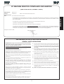
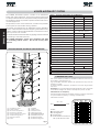
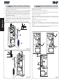
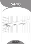
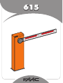
615
INDEX
EC MACHINE DIRECTIVE COMPLIANCE DECLARATION .............................................................................................. 2
IMPORTANT NOTICE FOR THE INSTALLER .................................................................................................................... 2
1 DESCRIPTION AND TECHNICAL SPECIFICATIONS .................................................................................................... 3
1.1 MAXIMUM USE CURVE ............................................................................................................................................. 3
2 ELECTRICAL DEVICES (standard system)................................................................................................................ 4
3 DIMENSIONS .......................................................................................................................................................... 4
ENGLISH
4 INSTALLING THE AUTOMATIC SYSTEM...................................................................................................................... 4
4.1 PRELIMINARY CHECKS ............................................................................................................................................. 4
4.2 MASONRY FOR FOUNDATION PLATE ........................................................................................................................ 4
4.3 MECHANICAL INSTALLATION .................................................................................................................................... 4
4.4 INSTALLING AND ADJUSTING THE BALANCING SPRING ............................................................................................ 5
4.5 CONVERTING FROM RIGHT-HAND TO LEFT-HAND VERSION ...................................................................................... 5
5 START-UP................................................................................................................................................................. 6
5.1 ADJUSTING TRANSMITTED TORQUE .......................................................................................................................... 6
5.2 ADJUSTING THE MECHANICAL STROKE LIMITERS ...................................................................................................... 6
5.3 ADJUSTMENT OF MAGNETIC STROKE LIMIT-SWITCHES ............................................................................................. 6
5.4 AUTOMATION TEST ................................................................................................................................................... 6
6 MANUAL OPERATION .............................................................................................................................................. 6
7 RESTORING NORMAL OPERATION MODE ................................................................................................................ 6
8 BALANCING SPRINGS ............................................................................................................................................. 6
8.1 SPRINGS FOR RECTANGULAR AND SKIRTED BEAMS ................................................................................................. 6
8.2 SPRINGS FOR RECTANGULAR BEAMS WITH FOOT AND WITH SKIRT AND FOOT ......................................................... 6
9 AVAILABLE ACCESSORIES ....................................................................................................................................... 7
10. MAINTENANCE .................................................................................................................................................... 7
10.1 TOPPING UP OIL .................................................................................................................................................... 7
11 REPAIRS................................................................................................................................................................ 7
Notes on reading the instruction
Read this instrument manual to the full before you begin installing the product.
The symbol
indicates notes that are important for the safety of persons and for the good condition
of the automated system.
The symbol
draws your attention to the notes on the characteristics and operation of the product.
1
EC MACHINE DIRECTIVE COMPLIANCE DECLARATION
(DIRECTIVE 89/392 EEC, APPENDIX II, PART B)
Manufacturer:
FAAC S.p.A.
Address:
Via Benini, 1
40069 - Zola Predosa BOLOGNA-ITALY
• is intended to be incorporated into machinery, or to be assembled with other machinery to constitute machinery
in compliance with the requirements of Directive 89/392 EEC, and subsequent amendments 91/368 EEC, 93/44
EEC and 93/68 EEC;
• complies with the essential safety requirements in the following EEC Directives:
73/23 EEC and subsequent amendment 93/68 EEC.
89/336 EEC and subsequent amendments 92/31 EEC and 93/68 EEC.
and furthermore declares that unit must not be put into service until the machinery into which it is incorporated or
of which it is a component has been identified and declared to be in conformity with the provisions of Directive
89/392 EEC and subsequent amendments enacted by the national implementing legislation.
Bologna, 03 March 2006
Managing Director
A. Bassi
IMPORTANT NOTICE FOR THE INSTALLER
GENERAL SAFETY REGULATIONS
1) WARNING! FAAC strongly recommends to follow these instructions literally
for the safety of persons. Improper installation or misuse of the product
will cause very serious damages to persons.
14) The automation is fitted with an anti-crush safety system that is a torque
control device. In any case, further safety devices shall be installed.
15) The safety devices (e.g. photocells, safety edges, etc.) protect areas
wherethere is a mechanical movement hazard, e.g. crushing, entrapment
and cutting.
2) Packaging material (plastic, polystyrene etc.) is a potential hazard and
must be kept out of reach of children.
3) Read the instructions carefully before installing the product.
4) Keep these instructions for future reference.
16) Each installation must be fitted with at least one fashing light (e.g.
FAAC LAMP, MINILAMP etc) as well as a warning plate suitably fixed
to the gate, besides the safety devices as per point 15. above.
5) This product has been designed and manufactured only for the use
stated in this manual. Any other use not expressly set forth will affect
the reliability of the product and/or could be source of hazard.
17) FAAC cannot be held responsible regarding safety and correct
functioning of the automation in the event that parts other than FAAC
original parts are used.
6) FAAC S.p.A. cannot be held responsible for any damage caused by
improper use or different from the use for which the automation system
is destined to.
19) Do not carry out any modifications to automation components.
18) Use only FAAC original spare parts for maintenance operations.
7) Do not use this device in areas subject to explosion: the presence of
flammable gas or fumes is a serious hazard.
20) The installer must supply all information regarding manual operation
of the system in the event of an emergency and provide the end-user
with the leaflet attached to the product.
8) The system must be constructed in compliance with the following
Standards: EN12604, EN12605, EN12453,EN12445 with the exception
of vehicles only systems which, however, must be provided with signs
specifying use for vehicles only.
For non-EU countries, to obtain an adequate level of safety, the
Standards mentioned above must be observed, in addition to national
legal regulations.
21) Keep out of persons when the product is in operation.
22) Keep out of reach of children the remote radio controls and any control
devices. The automation could be operated unintentionally.
23) The end-user must avoid any attempt to repair or adjust the automation
personally. These operations must be carried out exclusively by
qualified personnel.
9) FAAC cannot be held responsible for failure to observe technical
standards in the construction of gates and doors, or for any deformation
of the gates which may occur during use.
24) What is not explicitly stated in these instructions is not permitted.
10) Before carrying out any operations, turn off the system’s main switch.
11) An omnipower switch shall be provided for the installation with an
opening distance of the contacts of 3 mm or more. Alternatively, use a
6A thermomagnetic breaker with multi-pole switching.
12) Ensure that there is a differential switch up-line of the electrical system,
with a trip threshold of 0.03A.
13) Check that the earthing plant is in perfect condition and connect it to
the metallic parts. Also earth the yellow/green wire of the operator.
2
ENGLISH
Hereby declares
that:
the 615 BRP automation system
615BPR AUTOMATIC SYSTEM
ENGLISH
The 615BPR automatic system consists of an aluminium
beam with reflex reflectors, and a steel upright subjected
to cataphoresis treatment and painted with polyester paint.
The upright houses the hydraulic operator and the electronic
control equipment.
TABLE 1
Technical specifications of “615BPR barrier”
BARRIER MODEL
615BPR STD
615BPR RAP
5
2,5
Max. opening time (sec)
5,7
2,9
The operator, which moves the beam, consists of a hydraulic
power pack and a double-acting cylinder.
Angle speed (rad/sec)
0.28
0,54
Pump flow-rate (l/min)
1.5
3
The system is supplied with an adjustable torque limitation
system. It also includes a device stopping the beam in any
position, and a handy manual release command for use in
case of power cuts or faults.
Max. torque (Nm)
400
300
Beam max. length (m)
Rectangular/Rectangular
Skirt Articulated
Types of beam
Use frequency (at 20°C)
The beam and the relevant balancing spring must be ordered
by referring to the sales price list.
Max.consecutive cycles (at 20°C)
40%
220
340
230V~ (+6 -10 %) 50Hz
Power supply
The 615BPR automatic system was designed and built
for controlling vehicle access. Do not use for any other
purpose.
50%
220
Absorbed power (W)
FAAC HP OIL
Type of oil
0,9
Oil quantity (Kg)
1 DESCRIPTION AND TECHNICAL SPECIFICATIONS
Winding thermal protection
120° C
Torque adjustment system
standard by-pass valves
-40 ÷ +55 °C
Ambient temperature
Hood protective treatment
cataphoresis
Polyester RAL 2004
Hood paint
IP 44
Protection class
34
Weight (Kg)
270 x 1015 x 140
Upright overall dimensions LxHxD(mm)
Electric motor technical specifications
1400
RPM
2800
220
Capacity (W)
1
Absorbed current (A)
230V~ (+6 -10 %) 50Hz
Power supply
1.1 MAXIMUM USE CURVE
The curve makes it possible to establish maximum work time (T)
according to use frequency (F).
E.g. The 615BPR automatic system can operate non-stop at a use
frequency of 50%.
To ensure efficient operation, operate in the work range below
the curve.
Important: The curve is obtained at a temperature of 20°C. Exposure
to the direct sunlight can reduce use frequency down to 20%.
Calculation of use frequency
The percentage of effective work time (opening + closing) compared
to cycle total time (opening + closing + pause times).
Calculation formula:
%F =
햲
햳
햴
햵
햶
햷
햸
햹
foundation plate
barrier upright
electronic equipment
emergency release
torque adjustment screws
double-acting piston
stroke limit screw
beam
햺
햻
햽
햾
햿
헀
헁
헂
equaliser
oil filling plug
breather screw
balancing spring
spring adjustment tie-rod
hydraulic pump unit
stroke limit sensors
stroke limit magnets
OT + CT
Ta + Tc + Tp + Ti
X 100
where:
Ot =opening time
Ct =closing time
Pt =pause time
It = interval time between a
full cycle and the next.
fig.1
10
3
2 ELECTRICAL DEVICES (standard system)
RX
햲
햳
햴
햵
햶
fig.2
615BPR actuator
Photocells
Key push-button
Flashing lamp
Receiver
fig.4
1) To lay cables, use adequate rigid and/or flexible
tubes.
2) Always separate connection cables of low voltage
accessories from 230V~ supply cables. To prevent any
interference whatever, use separate sheaths.
fig.5
4.3 MECHANICAL INSTALLATION
1) Remove the cover, unscrewing the screws securing it
to the upright.
2) Using the four nuts and washers supplied, secure the upright
to the foundation plate (fig.5 ref.A). Remember that the
upright door should normally face the building.
3) Decide whether the installation is right-hand (Fig. 7/A)
or left-hand (Fig. 7/B) in connection with the references
below.
The 615BPR automated system is always
supplied in the right-hand version - for left-hand
installation, see chapter 4.5.
Make sure that the piston rod fitted on the rocker arm
is fully extended (corresponding to the beam's vertical
position).
4) Remove and store the breather screw as shown in fig.9
ref.A.
5) Assemble the flange (fig.6-ref.1) centrally, on the shaft
(Fig.6-rif 2), checking if the holes securing it to the beam
are on the closing side.(Fig.6-ref 3)
Position the washer (Fig.6-Ref.4) and carry out the tightening
operations of the screw and relevant grower (Fig. 6ref. 5).
Tightening requires considerable force as the
flange is secured on the hexagonal shaft by
interference.
6) Vertically fit the beam (Fig.6-ref 6) on the flange (Fig.6-ref
1) and secure it with the supplied screws (Fig.6 ref.7).
7) Fit the protective cover (Fig.6 ref.8) on the flange (Fig.6-ref
6) and secure it with the supplied screws (fig.6 ref.1).
Install and adjust the balancing spring.
3 DIMENSIONS
Values are in mm.
fig.3
4 INSTALLING THE AUTOMATIC SYSTEM
4.1 PRELIMINARY CHECKS
To ensure safety and an efficiently operating automatic
system, make sure the following conditions are observed:
•
•
•
•
•
When moving, the beam must not, on any account,
meet any obstacles or power cables.
The soil must permit sufficient stability for the foundation
plinth.
There must be no pipes or electric cables in the plinth
excavation area.
If the barrier body is exposed to passing vehicles, if
possible make use of adequate means of protection
against accidental impact.
Check if an efficient earth socket is available for
connection to the upright. Use the supplied nuts and
washer (fig. 5 ref.B).
4.2 MASONRY FOR FOUNDATION PLATE
1) Make a foundation plinth as shown in fig.4 (referred to
clayey soil)
2) Wall the foundation plate as shown in fig.4, supplying
one or more sheaths for routing electric cables. Using a
spirit level, check if the plate is perfectly level. Wait for
the cement to set.
fig.6
4
ENGLISH
TX
4.5 CONVERTING FROM RIGHT-HAND TO LEFT-HAND
VERSION
ENGLISH
4.4 INSTALLING AND ADJUSTING THE BALANCING
SPRING
1) Check if the balancing spring matches the type of beam
installed: see chapter 8.
2) Take the bronze bush (fig.7 ref.1) from the supplied
package, fit it in the tie-rod (fig.7 ref.2) and secure it to
the equaliser with M10 screw and washer (fig.7 ref.4).
3) While always keeping the beam in vertical position,
assemble the tie-rod (fig.7 ref.2) on the spring (fig.7 rif.3),
supplied separately.
4) Release the operator (see chapter 6) and position
the beam at 45°, then adjust the tie-rod and set the
spring until the weight of the beam is balanced in that
position.
5) Restore normal operation as described in chapter 7.
Procedure for converting a right-hand version to left-hand:
Release the operator.
Loosen the connection (fig.8 ref.A)
Provisionally remove the screw securing the piston (fig. 8 ref.
B) and the seeger ring (fig.8 ref.C).
Turn the rocker arm.
Position the piston on the left and secure it with the screw
(fig.8 ref.D) and seeger ring (fig.8 ref.E) you had previously
removed.
Tighten the connection (fig.8 ref.F).
Re-lock the operator.
Remove the enclosure of the electronic equipment and
re-install it on the left side of the bonnet, using the existing
holes.
Change over the connectors of the stroke-limit sensors (J6
and J9 on the 596/615BPR equipment).
fig.7/A
fig.8
fig.7/B
5
6 MANUAL OPERATION
5 START-UP
If the barrier has to be moved manually due to a power cut
or fault of the automatic system, use the release device
as follows:
5.1 ADJUSTING TRANSMITTED TORQUE
To set the hydraulic system controlling transmitted power,
turn the two by-pass screws (fig.9 ref.B).
The red screw controls closing movement torque.
The green screw controls opening movement torque.
To increase torque, turn the screws clockwise.
To reduce torque, turn the screws anti-clockwise.
UNLOCK
B
fig. 12
fig.9
- Fit the standard triangular key (Fig.12) in the lock and turn
it anti-clockwise through 1 turn.
5.2 ADJUSTING THE MECHANICAL STROKE LIMITERS
- Open and close the barrier manually.
Adjust the position of the beam to maximum closing and
opening positions, using the stroke limit mechanical stops
as shown in fig. 10 ref. 1.
7 RESTORING NORMAL OPERATION MODE
To prevent an involuntary pulse from activating the barrier
during the manoeuvre, before restoring normal operation,
switch off power to the system, and turn the triangular key
clockwise until it stops, and then remove it.
8 BALANCING SPRINGS
The 615BPR automatic system requires a balancing spring,
which must be ordered separately. The spring varies according
to length and type of beam (rigid, skirt or articulated).
fig. 10
5.3 ADJUSTMENT OF MAGNETIC STROKE LIMIT-SWITCHES
Consult the tables below to see if the spring matches.
The point where the automated system begins to make
the slow-down movement can be modified, by moving the
magnetic cylinder inside the seat located on the two arms
of the equaliser in the motion unit (Fig.10 - ref.2).
8.1 SPRINGS FOR RECTANGULAR AND SKIRTED BEAMS
Tab. 2
5.4 AUTOMATION TEST
After installation, apply the danger warning sticker on the
top of the upright (Fig 11).
Check operating efficiency of the automatic system and
all accessories connected to it.
Hand the “User’s Manual” to the Client, explain correct
operation and use of the barrier, and indicate the potentially
dangerous areas of the automatic system.
BALANCING SPRING
Ø
rectangulare
beam
skirted
beam
code
5,5
1315 – 2315
1315 - 2315
721008
6,0
2316 – 2815
2316 – 2815
721005
7,0
2816 – 3815
2816 – 3815
721007
7,5
8,0
721006
3816 – 4815
721018
8.2 SPRINGS FOR RECTANGULAR BEAMS WITH FOOT
AND WITH SKIRT AND FOOT
Tab. 3
BALANCING SPRING
Ø
beam
with foot
beam with skirt
and foot
code
5,5
1315 – 1815
1315 - 1815
721008
6,0
1816 – 2315
1816 – 2315
721005
7,0
2316 – 2815
2316 – 3315
721007
7,5
8,0
fig. 11
6
2816 – 3815
721006
721018
ENGLISH
LOCK
ARTICULATION KIT (fig.16)
9 AVAILABLE ACCESSORIES
The articulation kit makes it possible to articulate a rigid
beam to a maximum ceiling height of 3 m (see specific
instructions).
If an articulation kit is installed, the balancing spring
must be adapted.
SKIRT KIT (fig.13)
ENGLISH
The skirt kit increases visibility of the beam.
It is available in lengths from 2 m to 3 m.
If a skirt kit is installed, the balancing spring
must be adapted.
fig. 16
END FOOT (fig.17)
The end foot allows the beam to rest when closed and thus
prevents the profile bending downward.
If a foot is installed, the balancing spring must be
readjusted.
fig. 13
FORK SUPPORT (fig.14)
The fork has two functions:
- it prevents the beam, when closed, from bending and
splitting if its end is stressed by extraneous forces.
- it allows the beam to rest when closed and thus prevents
the profile bending downward.
fig. 17
10 MAINTENANCE
Whenever doing maintenance, always check correct
settings of the by-pass screws, system balancing, and
efficiency of safety devices.
fig. 14
10.1 TOPPING UP OIL
Periodically check quantity of oil inside the tank.
POSITIONING THE FORK SUPPORT FOUNDATION PLATE
An annual check is sufficient for low to medium use frequency;
for heavier duty, check every 6 months.
The level must not fall below the low mark on the stick
(fig.18).
To top-up, unscrew the filling plug (fig.18) and pour oil to
MAX level on the stick.
Use only FAAC HP OIL oil and no other.
Dimensions are in mm.
fig. 15
To position the fork support foundation plate, refer to fig.15
where:
P1
P2
L
A
=
=
=
=
fig. 18
barrier foundation plate
fork support foundation plate
beam length (in mm)
L - 195 (in mm)
11 REPAIRS
For repairs, contact FAAC’s authorised Repair Centres.
7
USER'S OPERATING MANUAL
615BPR AUTOMATED SYSTEM
GENERAL SAFETY REGULATIONS
If correctly installed and used, the 615BPR automatic system
ensures a high degree of safety.
Some simple rules on behaviour can prevent accidental
trouble:
- Do not pass under the beam when it is moving. Wait for
the beam to open fully before passing under it.
- Do not, on any account, stay under the beam.
- Do not stay near the automatic system, and do not allow
children, persons or things to do so, especially when it is
operating.
- Keep radio controls or other pulse generators away from
children, to prevent the automatic system from being
activated involuntarily.
- Do not allow children to play with the automatic system.
- Do not willingly obstruct beam movement.
- Prevent any branches or shrubs from interfering with beam
movement.
- Keep indicator-lights efficient and easy to see.
- Do not attempt to activate the beam by hand unless you
have released it.
- In the event of malfunctions, release the beam to allow
access and wait for qualified technical personnel to do
the necessary work.
- When you have set manual operation mode, cut power
to the system before restoring normal operation.
- Do not in any way modify the components of the automation
system.
- Do not attempt any kind of repair of direct action whatever
and contact qualified personnel only.
- At least every six months: arrange for qualified personnel
to check the automatic system, safety devices and earth
connection.
movement.
A stop pulse (if supplied) always stops movement.
For details on barrier behaviour in different function logics,
consult the installation Technician.
The automatic systems include safety devices (photocells)
that prevent the beam from re-closing when there is an
obstacle in the area they protect.
The 615BPR automatic system is supplied (as a standard item)
with an anti-crushing protection safety devices which limits
the torque transmitted to the beam.
The hydraulic system guarantees the beam is stopped in
any position.
Manual opening is, therefore, only possible by using the
release system.
The (flashing) indicator-light indicates that the beam is
moving.
MANUAL OPERATION
If the barrier has to be moved manually due to a power cut
or fault of the automatic system, use the release device as
follows:
The supplied key is triangular.
LOCK
DESCRIPTION
The 615BPR automatic system is an ideal barrier for controlling
vehicle access areas up to 5 m in width and of medium
transit frequency.
The hood contains a hydraulic pump unit, a double-acting
cylinder, and the beam balancing spring.
The beam consists of an aluminium profile with red reflex
reflectors so it can easily be seen even in the dark.
Barrier operation is controlled by a electronic control unit
housed in an enclosure with adequate degree of protection
against atmospheric agents, and which can be housed
inside the hood.
The beam is normally closed in horizontal position.
When the electronic control unit receives an opening
command via the radio control or any other pulse generator,
it activates the hydraulic equipment which rotates the beam
through 90° until it reaches the vertical position allowing
access. If automatic mode was set, the beam closes
automatically after selected pause time has elapsed.
If the semi-automatic mode was set, a second pulse must
be sent to close the beam.
An opening pulse given during re-closing always reverses
UNLOCK
fig. 1
- Fit the triangular key (Fig.1) in the lock and turn it
anti-clockwise through 1 turn.
- Open and close the barrier manually.
RESTORING NORMAL OPERATION MODE
To prevent an involuntary pulse from activating the barrier
during the manoeuvre, before restoring normal operation,
switch off power to the system, and turn the triangular key
clockwise until it stops, and then remove it.
Leggere completamente questo manuale di istruzioni prima di iniziare l’installazione del prodotto.
Il simbolo evidenzia le note importanti per la sicurezza delle persone e l’integrità dell’automazione.
Il simbolo richiama l’attenzione sulle note riguardanti le caratteristiche od il funzionamento del prodotto.
Read this instruction manual to the letter before you begin to install the product.
Symbol highlights notes that are important for people’s safety and for the good condition of the automated system.
Symbol draws your attention to the notes about the product’s characteristics or operation.
Lire ce manuel d’instructions dans son entier avant de commencer l’installation du produit.
Le symbole met en évidence les remarques pour la sécurité des personnes et le parfait état de l’automatisme.
Le symbole attire l’attention sur les remarques concernant les caractéristiques ou le fonctionnement du produit.
Vor der Installation des Produkts sind die Anweisungen vollständig zu lesen.
Mit dem Symbol sind wichtige Anmerkungen für die Sicherheit der Personen und den störungsfreien Betrieb der Automation gekennzeichnet.
Mit dem Symbol wird auf Anmerkungen zu den Eigenschaften oder dem Betrieb des Produkts verwiesen.
Lean completamente este manual de instrucciones antes de empezar la instalación del producto.
El símbolo identifica notas importantes para la seguridad de las personas y para la integridad de la automación.
El símbolo llama la atención sobre las notas relativas a las características o al funcionamiento del producto.
Lees deze instructiehandleiding helemaal door alvorens het product te installeren.
Het symbool is een aanduiding van opmerkingen die belangrijk zijn voor de veiligheid van personen en voor een goede
automatische werking.
Het symbool vestigt de aandacht op opmerkingen over de eigenschappen of de werking van het product.
Le descrizioni e le illustrazioni del presente manuale non sono impegnative. La FAAC si riserva il diritto, lasciando inalterate le caratteristiche essenziali dell’apparecchiatura, di apportare in qualunque momento e senza impegnarsi
ad aggiornare la presente pubblicazione, le modifiche che essa ritiene convenienti per miglioramenti tecnici o per
qualsiasi altra esigenza di carattere costruttivo o commerciale.
The descriptions and illustrations contained in the present manual are not binding. FAAC reserves the right, whilst
leaving the main features of the equipments unaltered, to undertake any modifications it holds necessary for either
technical or commercial reasons, at any time and without revising the present publication.
Les descriptions et les illustrations du présent manuel sont fournies à titre indicatif. FAAC se réserve le droit d’apporter à
tout moment les modifications qu’elle jugera utiles sur ce produit tout en conservant les caractéristiques essentielles,
sans devoir pour autant mettre à jour cette publication.
Die Beschreibungen und Abbildungen in vorliegendem Handbuch sind unverbindlich. FAAC behält sich das Recht
vor, ohne die wesentlichen Eigenschaften dieses Gerätes zu verändern und ohne Verbindlichkeiten in Bezug auf die
Neufassung der vorliegenden Anleitungen, technisch bzw. konstruktiv/kommerziell bedingte Verbesserungen vorzunehmen.
Las descripciones y las ilustraciones de este manual no comportan compromiso alguno. FAAC se reserva el derecho,
dejando inmutadas las características esenciales de los aparatos, de aportar, en cualquier momento y sin comprometerse a poner al día la presente publicación, todas las modificaciones que considere oportunas para el perfeccionamiento técnico o para cualquier otro tipo de exigencia de carácter constructivo o comercial.
De beschrijvingen in deze handleiding zijn niet bindend. FAAC behoudt zich het recht voor op elk willekeurig moment de
veranderingen aan te brengen die het bedrijf nuttig acht met het oog op technische verbeteringen of alle mogelijke
andere productie- of commerciële eisen, waarbij de fundamentele eigenschappen van de apparaat gehandhaafd
blijven, zonder zich daardoor te verplichten deze publicatie bij te werken.
FAAC S.p.A.
Via Benini, 1
40069 Zola Predosa (BO) - ITALIA
Tel. 0039.051.61724 - Fax. 0039.051.758518
www.faac.it
www.faacgroup.com
732387 - Rev. C