1
2
IDS LCD Keypad User Manual 700-292-01C Issued March 2009
3
IDS LCD Keypad User Manual 700-292-01C Issued March 2009
4
IDS LCD Keypad User Manual 700-292-01C Issued March 2009
Contents
1.
Introduction to the IDS LCD Digital Keypad.................................................8
2.
2.1
2.1.1
2.1.2
2.2
2.2.1
2.2.2
2.3
2.4
2.5
Arming the Control Panel...............................................................................8
Away Arming...........................................................................................................8
How to Away Arm...................................................................................................8
Quick Away Arm – Shortcut Key.............................................................................8
Stay Arming.............................................................................................................9
How to Stay Arm.....................................................................................................9
Quick Stay Arm – Shortcut Key..............................................................................9
How to Stay Arm and Go........................................................................................10
Key-switch or Remote Arming................................................................................10
Auto Arming............................................................................................................10
3.
3.1
3.2
Disarming the Control Panel..........................................................................10
How to Disarm with a User Code...........................................................................10
How to Disarm using a key-switch or Remote.......................................................11
4.
4.1
4.2
Bypassing Zones............................................................................................11
How to Bypass a Zone...........................................................................................11
How to Un-bypass a Zone.....................................................................................12
5.
5.1
5.2
5.3
5.4
Emergency Alarms.........................................................................................12
Fire Alarms.............................................................................................................12
Panic Alarms..........................................................................................................12
Medical Alarms......................................................................................................13
Duress Alarms.......................................................................................................13
6.
Alarm Memory................................................................................................13
7.
7.1
Zone Options..................................................................................................13
Changing a Zone Name.........................................................................................13
8.
8.1
8.2
8.3
8.3.1
8.3.2
8.3.3
8.3.4
8.3.5
8.3.5.1
8.3.5.2
8.3.5.3
8.3.5.4
8.3.5.5
8.3.5.6
8.3.5.7
8.3.5.8
8.3.5.9
8.3.5.10
User Codes......................................................................................................14
Adding, Deleting and Editing User Codes.............................................................15
How to Enter the User Program Mode...................................................................15
Explanation of Programmable Options..................................................................16
Option 0 – Add a New User Code.........................................................................16
Option 1 – Edit a User Name.................................................................................16
Option 2 – Edit a Selected User Code...................................................................17
Option 3 – View a User Code Slot Number............................................................18
Option 4 – User Code Properties...........................................................................18
Explanation of User Code Properties – Master Code............................................19
Duress Code..........................................................................................................19
Maid‟s Code...........................................................................................................19
Global Arm/Disarm.................................................................................................19
Group Arm..............................................................................................................20
Group Disarm.........................................................................................................20
Report User Open/Close........................................................................................20
User Phone in Access............................................................................................20
Report User Access...............................................................................................20
Enable Anti-Pass Back for User.............................................................................20
5
IDS LCD Keypad User Manual 700-292-01C Issued March 2009
8.3.5.11
8.3.6
8.3.7
8.3.8
8.3.9
8.3.10
8.3.11
8.3.12
8.3.13
Fire Code................................................................................................................21
Option 5 – Assign User Code to Partitions.............................................................21
Option 6 – Assign User Code to Doors..................................................................21
Option 7 – Assign User Code to Schedule.............................................................22
Option 8 – Adding User Remotes...........................................................................22
Option 9 – Delete User Code (Code Known).........................................................23
Option 10 – Delete a User Code (Slot Known).......................................................23
Option 11 – Viewing a User Code...........................................................................23
Option 12 – Add User Slot......................................................................................24
9.
9.1
9.2
9.3
Stay Zones.......................................................................................................24
How to Select a Stay Profile...................................................................................24
How to Program Stay Zones..................................................................................24
How to Cancel Stay Zones.....................................................................................25
10.
10.1
10.2
Buzz Zones......................................................................................................25
How to Program Buzz Zones..................................................................................25
How to Cancel Buzz Zones....................................................................................26
11.
11.1
11.2
Chime Zones...................................................................................................26
How to Program Chime Zones...............................................................................26
How to Cancel Chime Zones..................................................................................27
12.
Viewing Trouble Conditions...........................................................................27
13.
Changing a Partition.......................................................................................28
14.
Remote Telephone Access............................................................................28
15.
Output Control via a Keypad..........................................................................30
6
IDS LCD Keypad User Manual 700-292-01C Issued March 2009
Tables
Table 1
Alarm Panel Zones.........................................................................................13
Table 2
Alarm Panel Features.....................................................................................14
Table 3
User Programming Options...........................................................................15
Table 4
User Code Properties.....................................................................................19
Table 5
Trouble Conditions.........................................................................................27
Table 6
Remote Telephone Operation.......................................................................29
7
IDS LCD Keypad User Manual 700-292-01C Issued March 2009
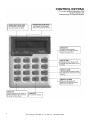
1.
Introduction to the IDS LCD Digital Keypad
Your installer has selected one of the finest alarm systems available for your installation and has custom
programmed the system features to meet your specific requirements.
The elegant and user friendly LCD Keypad will allow you easy access to your security system's functions
and information at the touch of a button. The 32 character screen will display menus and messages to
guide you through the system's operation.
Since you will communicate your instructions to your system through the keypad, please read this
manual carefully, and have your installer explain basic system operation.
2.
Arming the Control Panel
2.1
Away Arming
2.1.1
How to Away Arm
[#] + [USER CODE] (Leave via Entry/Exit Zone)
1.
2.
Ensure that the LCD display reads 'Ready to Arm' alongside the partition number being armed. If
not, check that all protected doors and windows are closed and that all movement has ceased in
areas covered by motion detectors. If necessary, bypass any required zones and close the front
door.
Press the [#] key.
3.
Enter a valid [USER CODE]. If an incorrect code is entered, the keypad buzzer will beep three
times. In the event of an error press, the [#] key and re-enter the code.
4.
The ARM indicator will come on and the keypad buzzer will sound for the duration of the exit
delay. The LCD screen will read 'Exit Delay' alongside the partition number which is being armed.
Any bypassed zones will be displayed on the LCD display as solid text. Any violated zones will be
displayed on the LCD display as flashing text. To scroll through zones which have been
bypassed or violated use the [PANIC] and [MED] keys.
5.
Leave only via a designated exit route. The panel will away arm at the end of the exit delay.
6.
Once the panel has armed the LCD display will read 'Armed' alongside the partition that has
been armed.
2.1.2
Quick Away Arm - Shortcut Key
(Hold down the [1] key until the keypad buzzer sounds)
If this function is enabled, it is possible to AWAY arm by simply holding down the [1] key. The LCD
display will read 'Exit delay' alongside the partition number being armed. The keypad buzzer sounds and
the arming process begins.
NOTE:
8
IDS LCD Keypad User Manual 700-292-01C Issued March 2009
If the partition is already STAY armed, this key will initialize AWAY arming. It is therefore possible to
change directly from STAY armed to AWAY armed.
2.2
Stay Arming
Stay arming allows the user to monitor selected perimeter zones and bypass interior zones. The user can
remain on the premises with access to designated areas during the STAY ARM cycle. Any zone which
may be violated accidentally should be programmed as a buzz zone. When violated, a buzz zone will
cause the keypad buzzer to sound for thirty seconds before sounding the siren. Entering a valid user
code before the siren sounds, prevents an alarm condition from being registered and will silence the
keypad buzzer and prevent the siren from sounding.
To provide greater flexibility the panel caters for the programming of two different STAY PROFILES. Each
STAY PROFILE contains a unique combination of STAY, BUZZ and ALARM zones which cater for a
particular STAY ARM requirement.
The profile number is now indicated at the end of the top line after the armed partition on the LCD
Keypad when the panel is stay armed.
Example:
PROFILE 1 might be used when the family goes to bed in the evening. In this profile, some interior zones
may be programmed as alarm zones or buzz zones, whereas PROFILE 2 is utilised while watching
television when all interior zones would be bypassed. (See 9.1 How to Select a Stay Profile.)
2.2.1
How to Stay Arm
[#] + [USER CODE] (Do not leave premises)
1.
2.
3.
4.
5.
6.
7.
8.
2.2.2
Select the required STAY PROFILE. (See Section 8.1)
Ensure that the LCD display reads 'Ready to arm' alongside the partition number being armed. If
not, check that all protected doors and windows are closed and that all movement has ceased in
the areas covered by motion detectors.
Press the [#] key.
Enter a valid [USER CODE]. If an incorrect code is entered, the keypad will give an error beep. In
the event of an error press the [#] key and re-enter the [USER CODE].
DO NOT violate the Entry/Exit zone (normally the front door). If the Entry/Exit zone is violated the
system will arm in the AWAY mode.
The LCD Keypad will read 'Exit Delay', the ARM indicator will come on and the keypad buzzer will
sound for the duration of the exit delay.
When the panel arms, any STAY zones will be automatically bypassed. These are displayed on
the LCD Display as solid text. Any violated zones will be displayed on the LCD Display as
flashing text. To scroll through zones which have been bypassed or violated use the [PANIC] and
[MED] keys.
Ensure that you enter only those areas that are bypassed.
Quick Stay Arm - Shortcut Key
(Hold down the [5] key for 2 seconds until the keypad buzzer sounds)
It is possible to STAY arm by holding down the [5] key until the keypad buzzer sounds. The panel will
immediately arm into the stay mode without any exit delay. Holding the [5] key again will toggle between
the 2 stay profiles.
9
IDS LCD Keypad User Manual 700-292-01C Issued March 2009
The LCD display will read 'Partial Arm' and will indicate any zones which have been bypassed. One is
able to scroll through the list of bypassed, as well as violated, zones by using the [PANIC] and [MED]
keys.
2.3
How to Stay Arm and Go
(Hold down the [6] key for two seconds until the keypad buzzer sounds)
This is a single key arm function, which allows the user to STAY arm and leave the premises.
If a partition is already stay armed, holding down the [6] key initiates an exit delay, thus allowing the user
to leave the premises without disarming. At the end of the exit delay, the partition will re-arm in the same
stay profile it was armed in before the [6] key was held down.
1.
Make sure all zones are clear. Hold down the [6] key until the keypad buzzer sounds. The LCD
screen display will read 'Exit Delay' alongside the partition number being armed. Any zones that
have been bypassed will be displayed on the LCD Display as solid text. Any zones that are
violated will be displayed on the LCD Display as flashing text. Use the [PANIC] and [MED] keys
to scroll through zones which have been bypassed or violated. The keypad buzzer will sound for
the duration of the exit delay. Only leave via a designated exit route.
2.
At the end of the exit delay, the ARM indicator will come on and the display will read 'Stay Arm'.
All stay zones will be bypassed.
2.4
1.
2.
3.
4.
Key-Switch or Remote Arming (If fitted)
Ensure that the LCD display reads 'Ready to arm' before leaving.
Leave and close the door (remembering to lock!)
Activate the remote or the key-switch. A remote can be used to Stay Arm or Away Arm.
The alarm will arm in the away mode.
NOTE:
If a remote control is used it is advisable to have the siren toot on arm function enabled. This provides
verification that the system has armed.
2.5
Auto Arming
The panel may be programmed to arm automatically at a preprogrammed time. Should the premises be
occupied at the time of auto arming, a valid [USER CODE] entered during the pre-arm delay will
terminate the arming sequence. The pre-arm delay is signalled by an exit beep.
3.
3.1
Disarming the Control Panel
How to Disarm with a User Code
[#] + [USER CODE]
To disarm the system, enter [#] followed by a valid [USER CODE].
1.
Enter the premises through a designated entry route. Entering via any other route will cause an
alarm.
10
IDS LCD Keypad User Manual 700-292-01C Issued March 2009
2.
3.
4.
5.
6.
As soon as the Entry/Exit zone is violated, the entry delay will begin. The keypad buzzer will
sound for the duration of the entry period. The above 2 points only apply if the premises are away
armed.
Press the [#] key and enter a valid [USER CODE]. If an error beep occurs, press the [#] key and
re-enter the user code.
Once the system disarms, the ARM indicator will turn off and the keypad buzzer will stop
sounding.
If no valid user code has been entered prior to the expiry of the entry delay period an alarm
condition will be registered.
If the entry period is too short, have your installer change the entry delay period.
NOTE:
If a strobe (or flashing light) has been installed and an alarm condition is registered, the strobe will
continue flashing after the siren has stopped sounding. Entering a valid [USER CODE] will cancel the
strobe.
3.2
1.
2.
4.
4.1
How to Disarm using a Key-Switch or Remote
Activate the remote or key-switch.
The system will disarm and the remote indicator (if installed) will turn off. If the siren toot on
disarm option is enabled, the siren will provide a double toot when the panel is disarmed.
Bypassing Zones
The term BYPASS is used to describe a zone which has been deactivated; i.e. violation of a
bypassed zone is ignored and will not cause an alarm condition.
Once the system is armed, it is not possible to bypass zones.
All bypassed zones will be automatically cancelled each time the panel is disarmed and must be
re-bypassed before the next arming.
How to Bypass a Zone
Hold down [9] + [ZONE NUMBER] + [*] + [#]
1.
2.
3.
4.
5.
6.
Ensure the panel is not armed.
To enter bypass mode, hold down the [9] key for two seconds until the keypad buzzer sounds
and all LED's are off.
The LCD display reads 'Bypassed'. Using the [PANIC] and [MED] keys, one is able to scroll
through the zones. Alternatively press the number of the zone you wish to bypass e.g. the [2] key
if you wish to bypass zone 2, then press the [*] key.
[Y] indicates that the zone has been bypassed, whilst [N] indicates that the zone has not been
bypassed.
Repeat step 3 to bypass other zones.
Press the [#] key to exit the bypass mode.
NOTE:
Panic zones cannot be bypassed.
11
IDS LCD Keypad User Manual 700-292-01C Issued March 2009
4.2
How to Un-Bypass a Zone
Hold down [9] + [ZONE NUMBER] + [*] + [#]
1.
2.
3.
4.
Enter bypass mode by holding down the [9] key until the keypad buzzer sounds. The power and
arm LED's will be off. All zones will be displayed on the screen with either a [Y] or a [N] alongside
the zone.
[Y] indicates that the zone has been bypassed, whilst [N] indicates that the zone has not been
bypassed.
Press the number corresponding to the currently bypassed zone, then press the [*] key.
Alternatively use the [PANIC] or [MED] keys to scroll through the zones.
Press the [#] key to exit User Program Mode.
5.
Emergency Alarms
5.1
Fire Alarms
[F]
(Hold down the [F] key for two seconds until the keypad buzzer sounds)
5.2
If the [F] key is pressed until the keypad beeps (approximately 2 seconds) a FIRE ALARM
condition will be activated. The Display reads 'Alarm!' alongside the relevant partition.
The FIRE ALARM CONDITION may also be triggered by a smoke detector connected to an
appropriately programmed zone.
The siren will sound on and off repeatedly if programmed and the FIRE REPORTING CODE will
be transmitted to the monitoring company.
To silence the siren enter a valid [USER CODE].
Panic Alarms
[P]
(Hold down the [P] key for two seconds until the keypad buzzer sounds)
If the [P] key is pressed until the keypad beeps (approximately 2 seconds) a PANIC ALARM
condition will be activated. The Display reads 'Alarm!' alongside the relevant partition number.
A PANIC ALARM may also be activated using any FIXED PANIC button or a REMOTE PANIC
button (if installed).
If the audible panic option has been selected, the siren will sound. A PANIC ALARM will be
transmitted to the monitoring company.
To silence the siren, enter a valid [USER CODE].
Press the [P] key only in an emergency situation which requires response by emergency
personnel.
12
IDS LCD Keypad User Manual 700-292-01C Issued March 2009
5.3
Medical Alarms
[M]
(Hold down the [M] key for two seconds until the keypad buzzer sounds)
If the [M] key is pressed until the keypad beeps (approximately 2 seconds) a MEDICAL ALARM
condition will be activated.
The keypad buzzer will beep 5 times.
A medical reporting code will be reported to the monitoring company.
5.4
Duress Alarms
[#] + [DURESS CODE]
This is a special user code that should only be used in the unique situation where an intruder
forces one to disarm the system “under duress”.
When a [DURESS CODE] is entered, the control panel disarms. A Duress Alarm Code (if
programmed) will be reported to the monitoring company.
It is advisable to choose a Duress code which can be easily remembered by all family (or staff)
members.
6.
Alarm Memory
The Alarm Memory displays any zones which were tampered, violated, or bypassed during the last arm
cycle. A flashing ARM indicator notifies the user of an Alarm Memory condition. To view the Alarm
Memory, disarm the panel and continue as follows:
[0]
(Hold down the [0] key for two seconds until the keypad buzzer sounds)
1.
2.
3.
4.
5.
6.
7.
Hold down [0] until the keypad buzzer sounds.
The ARM and POWER indicators will turn off and the keypad buzzer will sound briefly.
Use the [MED] or [PANIC] keys to scroll through the zones violated during the last armed
period.
Press 2 to display zones which were bypassed.
Press 3 to display which zones were tampered.
Press 1 to return to violated zones.
The Alarm Memory is erased at the beginning of each arm cycle.
7.
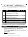
7.1
Zone Options
Changing a Zone Name
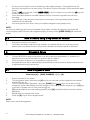
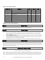
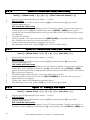
Table 1 : Alarm Panel Zones
Alarm Panel
IDS 816
Zones
1 - 16
Sub-location
12
13
IDS LCD Keypad User Manual 700-292-01C Issued March 2009
IDS 1224
IDS 1632
1 -24
1 - 32
12
12
For detailed programming instructions, please see the installation manual provided with your Alarm
Panel.
1.
2.
3.
4.
Press [#] + [INSTALLER CODE] + [*].
If the default installer code is four digits it will be [9999], if it is six digits, it will be [999999].
Enter the [LOCATION] as per table 1 above followed by the [*] key.
Enter the [SUB-LOCATION 12] followed by the [*] key.
Edit the Zone Name.
Notes on Editing a Zone Name
Use the [MODE] key to toggle between upper and lower case.
Use the [1] key to display a 1, to create a space or to display the following punctuation marks :
'!Use the [PANIC] key to scroll to the right.
Use the [MED] key to scroll to the left.
Pressing a key once will display the first letter displayed on the key. Pressing a key twice displays
the second letter on the key etc. Numerics are displayed after all available letters have been
displayed i.e. to display a 2, press the relevant key four times.
If you wish to use a different letter on the same key press the key the required number of times to
display the relevant letter, pause for one second. Once the cursor has advanced, you may begin
entering the next letter.
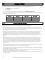
8.
User Codes
Each of the IDS Alarm Panels has a certain number of programmable user codes as displayed in Table 2
below. By default User Code 1 is the Master User Code which contains a pre-programmed 4 digit code
of 1234.
The number of partitions which can be programmed by your programmer also varies for the different IDS
Alarm Panels.
A partition is a group of zones which may be armed and disarmed independently without affecting zones
or users assigned to other partitions.
I.e. a guest cottage appended to a main house may be partition 2. The main house being partition 1.
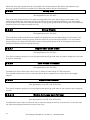
NOTE:
User codes may be 4 (default) or 6 digits long. This is a programmable feature. Check with your installer
to verify which option has been programmed.
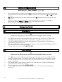
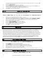
Table 2 : Alarm Panel Features
Alarm Panel
IDS 816
IDS 1224
IDS 1632
No. of User Codes
32
64
250
No. of Partitions
1-2
1–4
1–8
14
IDS LCD Keypad User Manual 700-292-01C Issued March 2009
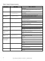
8.1
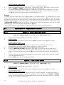
Adding, Deleting and Editing User Codes
Hold [*] + [MASTER USER CODE] + [*] + [PROGRAMMABLE OPTION] + [*]
All IDS Alarm Panels utilise a user-friendly programmable interface which allows the user to add, modify,
or delete user codes. See Table 3 for a summary of programmable options. The programmable interface
is accessed by entering the USER PROGRAMMING MODE.
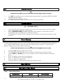
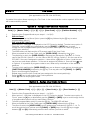
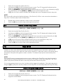
Table 3 : User Programming Options
Options
Summary of Programmable Options
Option 0 Allows for the addition of new user codes.
Option 1 Allows editing of the user name displayed by LCD keypads.
This menu is only applicable if LCD keypads are installed.
Option 2 Allows editing of a selected user code. Note that the user
code properties are not edited, only the user code itself.
Option 3 Allows viewing of the user code slot number for a selected
code.
Option 4 Allows editing of the user code properties for a selected
user code. This is a bitmapped menu.
Option 5 Allows the allocation of a selected user code to a
designated partition(s). This is a bitmapped menu.
Option 6 Assign User Code to Doors (bitmapped)
Option 7 Assign a User Code to a Schedule
Option 8 Allows a remote to be assigned to a specific user
Option 9 Allows a user to be deleted
Option 10 Allows the deletion of a user code using the user code slot
number.
Option 11 Allows viewing of a user name if the slot number is known.
Option 12 Add User by Slot Number
816
x
x
1224
x
x
1632
x
x
x
x
x
x
x
x
x
x
x
x
x
x
x
x
x
x
x
x
x
x
x
x
x
x
x
x
x
x
NB:
Text prompts displayed on LCD Keypads connected to the IDS 1224 and IDS 1632 are considerably
more detailed than text prompts displayed on the IDS 816 Alarm Panel.
8.2
1.
2.
3.
4.
5.
How to Enter the User Program Mode
Ensure that the panel is not armed.
Hold down the [*] key until the keypad buzzer sounds. The ARM indicator will flash.
The LCD prompt reads 'Enter Master Code'. The factory default is [1234]. Should the [MASTER
USER CODE] be set to six digits it will be [123456] by default.
After entering the [MASTER USER CODE], press the [*] key. A valid entry will be confirmed by
a long beep. If an invalid [MASTER USER CODE] was entered, the keypad buzzer will give an
error beep (3 short beeps).
If steps 1 - 4 are performed correctly:
IDS 816 Panel
The LCD display will prompt for a 'Menu Option'.
15
IDS LCD Keypad User Manual 700-292-01C Issued March 2009
6.
7.
IDS 1632 & IDS 1224 Panels
The first menu option - Menu Option 0 - 'Add User' is displayed by default.
Select a programmable option from Table 1. In the case of the IDS 1632 and IDS 1224, one may
use the [PANIC] or [MED] keys to scroll through the menu options.
Confirm the entry by pressing the [*] key. A valid entry is confirmed by a long beep. An invalid
entry will be signalled by means of an error beep (3 short beeps). If an error beep occurs, press
the [#] key to clear all previous entries, and repeat steps 2 – 6
Example:
To add a new user code, enter User Program Mode by completing steps 2 - 5 as listed above. In the
case of the IDS 816 when prompted to enter a 'Menu Option', enter a value of [0] (See table 1) followed
by [*]. In the case of the IDS 1632 and the IDS 1224, Menu Option 0 will be displayed on the LCD screen
by default. Press the [*] to confirm your entry. For all panels, once prompted to 'Enter a User Code', input
a [NEW USER CODE] followed by the [*] key. Once the user code is programmed, enter the next code
followed by [*]. To exit the program mode press the [#] key.
For a full list of options, refer to Table 2. Programming of these options is explained below.
8.3
8.3.1
Explanation of Programmable Options
Option 0 - Add a New User Code
Hold [*] + [Master Code] + [*] + [0] + [*] + [New Code] + [*]
1.
2.
3.
4.
5.
6.
8.3.2
Enter the User Program Mode as per steps 1 - 4 of (8.2).
IDS 816 Panel
When prompted for the 'Menu Option' press the [0] key followed by the [*] key to select
programmable option 0.
IDS 1632 & IDS 1224 Panels
Menu option 0 - 'Add User' is displayed on the LCD Screen by default. As this is the
programmable option you require, press the [*] key to confirm your entry.
The ARM key flashes and the LCD prompt reads 'Enter User Code'.
Enter the [NEW USER CODE] followed by the [*] key to confirm the entry. A valid entry is
confirmed by a long beep. An invalid entry will be signalled by means of an error beep (3 short
beeps). If an error beep occurs, press the [#] key to clear all previous entries and repeat steps
1 - 4.
Further codes can be added by repeating step 4 above. When a user code is added, it is stored
in the first available user slot.
Press the [#] key to exit the User Program Mode.
Option 1 - Edit a User Name
Hold [*] + [Master Code] + [*] + [1] + [*] + [User Code] + [*]
1.
2.
Enter the User Program Mode as per steps 1 - 4 of (8.2).
IDS 816 Panel
When prompted for the 'Menu Option' press the [1] key followed by the [*] key to select
programmable option 1.
IDS 1632 & IDS 1224 Panels
Menu option 0 - 'Add User' is displayed on the LCD Screen by default. To select menu option 1 'Edit Name', press the [1] key followed by the [*] key or alternatively use the [PANIC] or [MED]
keys to scroll through the list of programmable options until you reach Menu Option 1 and press
the [*] key to confirm your selection.
16
IDS LCD Keypad User Manual 700-292-01C Issued March 2009
3.
4.
5.
6.
7.
The ARM indicator flashes and the LCD prompt reads ' Enter User Code'.
Enter the [USER CODE] that you wish to edit. User Names are displayed as the User Slot
Number by default. Edit the User Slot Number so that it reads the correct User Name. (See Notes
on Editing a User Name).
To confirm the entry press [*].
Further names may be edited by repeating steps 4 - 6 above.
Press the [#] key to exit the User Program Mode.
Notes on Editing a User Name
Use the [MODE] key to toggle between upper and lower case.
Use the [1] key to display a 1, to create a space or to display the following punctuation marks :
'!Use the [PANIC] key to scroll to the right.
Use the [MED] key to scroll to the left.
Pressing a key once will display the first letter displayed on the key. Pressing a key twice displays
the second letter on the key etc. Numerics are displayed after all available letters have been
displayed i.e. to display a 2, press the relevant key four times.
If you wish to use a different letter on the same key press the key the required number of times to
display the relevant letter, pause for one second. Once the cursor has advanced, you may begin
entering the next letter.
The cursor will advance instantly if one presses another key.
Example:
You wish to change [USER 1] to read Brad.
1.
2.
3.
4.
5.
6.
8.3.3
To type in a (B), press the [2] key twice („B‟ is the second letter displayed on the key).
Text is defaulted to Upper case. Press the [MODE] key for lower case. Upper case text is
indicated by a thin flashing cursor, whilst lowercase text is indicated by a thicker flashing cursor.
To type in an (r) press the [8] key once („r‟ is the first letter displayed on the key).
To type in an (a) press the [2] key once ('a' is the first letter displayed on the key).
To type in the letter (d) press the [3] key once (d is the first letter displayed on the key).
To confirm your entry press the [*] key once.
Option 2 - Edit a Selected User Code
Hold [*] + [Master Code] + [*] + [2] + [*] + [Old Code] + [*] + [New Code] + [*]
1.
2.
3.
4.
5.
6.
Enter the User Program Mode as per steps 1 - 4 of (8.2).
IDS 816 Panel
When prompted for the 'Menu Option' press the [2] key followed by the [*] key to select
programmable option 2.
IDS 1632 & IDS 1224 Panels
Menu option 0 - 'Add User' is displayed on the LCD Screen by default. To select menu option 2 'Edit Name', press the [2] key or alternatively use the [PANIC] or [MED] keys to scroll through
the list of programmable options until you reach Menu Option 2. Press the [*] key to confirm your
selection.
The ARM indicator will flash and the LCD prompt reads 'Enter User Code'. Enter the [USER
CODE] you wish to edit.
Alongside the Data prompt, enter the [NEW CODE]. To move the cursor within the [NEW
CODE] use the [PANIC] or [MED] keys.
To confirm your entry press the [*] key.
The ARM indicator will flash.
17
IDS LCD Keypad User Manual 700-292-01C Issued March 2009
7.
8.
To edit other codes repeat steps 3 - 6.
Press the [#] key to exit the User Program Mode.
8.3.4
Option 3 - View a User Code Slot Number
Hold [*] + [Master Code] + [*] + [3] + [*] + [User Code] + [*]
1.
2.
Enter the User Program Mode as per steps 1 - 4 of (8.2).
IDS 816 Panel
When prompted for the 'Menu Option' press the [3] key followed by the [*] key to select
programmable option 3.
IDS 1632 & IDS 1224 Panels
Menu option 0 - 'Add User' is displayed on the LCD Screen by default. To select menu option 3 'View Slot num', press the [3] key or alternatively use the [PANIC] or [MED] keys to scroll through
the list of programmable options until you reach Menu Option 3. Press the [*] key to confirm your
selection.
The ARM indictor will flash and the LCD prompt reads 'Enter User Code'.
Once you have entered the [USER CODE] followed by the [*] key the Slot num is displayed
alongside the Data prompt.
To view other Slot numbers press the [*] key and repeat steps 3 - 5.
Press the [#] key to exit the User Program Mode.
3.
4.
5.
6.
8.3.5
Option 4 - User Code Properties
Hold [*] + [Master Code] + [*] + [4] + [*] + [User Code] + [*] + [Property Number] + [*]
1.
2.
3.
4.
5.
6.
7.
8.
Enter the User Program Mode as per steps 1 - 4 of (8.2).
IDS 816 Panel
When prompted for the 'Menu Option' press the [4] key followed by the [*] key to select
programmable option 4.
IDS 1632 & IDS 1224 Panels
Menu option 0 - 'Add User' is displayed on the LCD Screen by default. To select menu option 4 'User Options', press the [4] key or alternatively use the [PANIC] or [MED] keys to scroll
through the list of programmable options until you reach Menu Option 4. Press the [*] key to
confirm your selection.
The ARM indictor will flash and the LCD prompt reads 'Enter User Code'.
Once you have entered the [USER CODE], followed by the [*] key select a User Code property
by pressing the key which corresponds to that property.
In the case of the IDS 1632 and the IDS 1224, one may use the [PANIC] or [MED] keys to scroll
through the User Options which can be assigned to a user.
Pressing the [*] key toggles between [Y] and [N] for the selected user option.
Repeat steps 4 & 5 until the desired properties have been programmed.
To edit another User Code's properties, press the [#] key and repeat steps 2 - 5.
Press the [#] key twice to exit user program mode.
Example:
To enable a User Code to function as a duress code, when prompted for the Option press the [2] key
followed by the [*] key.
18
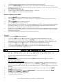
IDS LCD Keypad User Manual 700-292-01C Issued March 2009
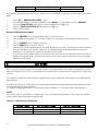
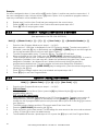
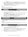
Table 4 : User Code Properties
Zone LED
1
2
3
4
5
6
7
8
9
10
11
12
Property
Master User
Duress Code
Arm to Disarm Code [Maid‟s Code]
Group Arm (Global Arm /Disarm for 816)
Group Disarm
Arm Code
Disarm Code
Report User Open Close
User Phone in Access
Report User Access
Enable Anti-pass back for User
Fire Code
816
X
X
X
X
1224
X
X
X
X
X
X
X
X
X
1632
X
X
X
X
X
X
X
X
X
X
X
X
Explanation of User Code Properties
8.3.5.1
Master User
When assigned to a user, this property allows the user to act as a Master User.
8.3.5.2
Duress Code
This is a special 4 (default) or 6 digit user code (check the code length with your installer) and
should only be used in the unique situation where an intruder forces one to disarm the system
"under duress".
When the [DURESS CODE] is entered, the control panel disarms normally - however a DURESS
REPORTING CODE is transmitted to the monitoring company to inform them that you have been
forced to disarm the control panel by an intruder.
It is advisable to choose a code that can be easily remembered by all family (or staff) members.
8.3.5.3
Maid's Code
This code may be used to limit access to the premises. A maid's code will only disarm the system if the
same code was used for arming. If armed with a code other than this code, the system will view an
attempt to disarm using a maid's code as an invalid entry. Any valid user code will disarm the system if it
has been armed with a maid‟s code.
8.3.5.4
Global Arm / Disarm Code
(Not applicable to the IDS 1224 & IDS 1632)
This code when entered will either arm or disarm the partitions assigned to that user depending on their
status. If both partitions are disarmed, entering a global code will arm both partitions. If both partitions are
armed, entering a global code will disarm them. In the case where one partition is armed and the other
19
IDS LCD Keypad User Manual 700-292-01C Issued March 2009
disarmed, entering a global code at the keypad of the armed partition will disarm that partition and
entering a global code at the keypad of the disarmed partition will arm that partition.
8.3.5.5
Group Arm
(Not applicable to the IDS 816)
This code when entered will arm the partitions assigned to the user depending on their status. If all
partitions are disarmed, entering a group code will arm all of the assigned partitions. In a case where
some partitions are armed and others disarmed, entering this group code at the keypad of the disarmed
partition will arm the disarmed partitions only.
8.3.5.6
Group Disarm
(Not applicable to the IDS 816)
This code when entered will disarm the partitions assigned to the user depending on their status. If all
partitions are armed, entering a group code will disarm all of the assigned partitions. In a case where
some partitions are disarmed and others armed, entering this group code at the keypad of the armed
partition will disarm the armed partitions only.
8.3.5.7
Report User Open Close
(Not applicable to the IDS 816)
This option enables reporting of a pre-programmed reporting code when a partition assigned to this user
is armed / disarmed.
8.3.5.8
User Phone in Access
(Not applicable to the IDS 816)
If enabled this option allows the user to arm or disarm a panel using a DTMF telephone.
If the installer selects the full menu, the user will be able to bypass zones, open doors and toggle
outputs.
8.3.5.9
Report User Access
(Not applicable to the IDS 1224 & IDS 816)
This option enables reporting of a pre-programmed reporting code when a user opens a door assigned
to them.
8.3.5.10
Enable Anti-pass back for User
(Not applicable to the IDS 1224 & IDS 816)
If enabled this option does not allow a user to enter an assigned area for a second time, if the user has
not exited the assigned area after the previous entry.
20
IDS LCD Keypad User Manual 700-292-01C Issued March 2009
8.3.5.11
Fire Code
(Not applicable to the IDS 1224 & IDS 816)
If enabled ,this option allows reporting of a Fire Code. In the event that this code is reported, all fire doors
will be automatically opened.
8.3.6
Option 5 - Assign User Code to Partitions
Hold [*] + [Master Code] + [*] + [5] + [*] + [User Code] + [*] + [Partition Number] + [*]
1.
2.
Enter the User Program Mode as per steps 1 - 4 of (8.2).
IDS 816 Panel
When prompted for the 'Menu Option' press the [5] key followed by the [*] key to select
programmable option 5.
IDS 1632 & IDS 1224 Panels
Menu option 0 - 'Add User' is displayed on the LCD Screen by default. To select menu option 5 'Partitions', press the [5] key or alternatively use the [PANIC] or [MED] keys to scroll
through the list of programmable options until you reach Menu Option 5. Press the [*] key to
confirm your selection.
The ARM indictor will flash and the LCD prompt reads 'Enter User Code'.
When prompted for the 'User Code‟ enter the [USER CODE] followed by the [*] key.
The partitions to which the [USER CODE] is assigned are indicated by Options 1 or 2 in the
case of the IDS 816, Options 1 - 4 in the case of the IDS 1224 or Options 1- 8 in the case of the
IDS 1632. If the user is assigned to partition 1, there will be a [Y] next to Option 1 and the user
can thus arm and disarm partition 1. If the user is assigned to partition 4, there will be a [Y] next
to Option 4. It is possible to program codes to arm / disarm any combination of the available
partitions.
To select which partitions the [USER CODE] may arm or disarm, toggle options by entering the
[PARTITION NUMBER] followed by the [*] key. One may also use the [PANIC] and [MED]
keys to scroll through the partitions.
Repeat step 6 until the User Code has been assigned to the correct partition(s).
Press the [#] key to edit another User Code's partitions.
Press [#] twice to exit program mode.
3.
4.
5.
6.
7.
8.
9.
8.3.7
Option 6 - Assign User Code to Doors
(Not applicable to the IDS 1224 & IDS 816)
Hold [*] + [Master Code] + [*] + [6] + [*] + [User Code] + [*] + [Door Number] + [*]
1.
2.
3.
4.
5.
Enter the User Program Mode as per steps 1 - 4 of (8.2).
Menu option 0 - 'Add User' is displayed on the LCD Screen by default. To select menu option 6 'Doors', press the [6] key or alternatively use the [PANIC] or [MED] keys to scroll through the list
of programmable options until you reach Menu Option 6.
To select programmable option 6, press the [*] key. The ARM LED will flash.
When prompted for the 'User Code' enter the [USER CODE] followed by the [*] key.
The doors to which the [USER CODE] can be assigned are indicated by Options 1 - 14. To
scroll through the list of options use the [PANIC] or [MED] keys. Use the [*] key to toggle
between [Y] and [N]. Alternatively press the door number you wish to select.
21
IDS LCD Keypad User Manual 700-292-01C Issued March 2009
Example:
If a user is assigned to door 1, there will be a [Y] next to Option 1 and the user can thus open door 1. If
the user is assigned to door 14 there will be a [Y] next to Option 14. It is possible to program codes to
open any combination of the available doors.
6.
7.
8.
Repeat step 5 until the User Code has been assigned to the correct doors.
Press the [#] key to edit another User Code's doors and repeat steps 4 & 5.
Press [#] twice to exit program mode.
8.3.8
Option 7 - Assign a User Code to a Schedule
(Not applicable to the IDS 1224 & IDS 816)
Hold [*] + [Master Code] + [*] + [7] + [*] + [User Code] + [*] + [Schedule Number] + [*]
1.
2.
3.
4.
5.
6.
7.
8.
8.3.9
Enter the User Program Mode as per steps 1 - 4 of (8.2).
Menu option 0 - 'Add User' is displayed on the LCD Screen by default. To select menu option 7 'Schedule', press the [7] key or alternatively use the [PANIC] or [MED] keys to scroll through the
list of programmable options until you reach Menu Option 7.
To select programmable option 7, press the [*] key. The ARM LED will flash.
When prompted for the 'User Code‟ enter the [USER CODE] followed by the [*] key.
Three schedule options exist. Schedule options are displayed next to the data prompt. If a user is
assigned to Schedule 0, the user may arm / disarm the premises at any given time. Users
assigned to Schedule 1 are allowed to arm / disarm the area only during the specified
programmed schedule times. The same applies to those users assigned to Schedule 2.
To select which schedule the [USER CODE] may be assigned to, press the relevant keypad key
followed by the [*] key.
Press [*] key to assign another user to a schedule and repeat steps 4 & 5.
Press [#] key to exit User Program Mode.
Option 8 - Adding User Remotes
Hold [*] + [Master Code] + [*] + [8] + [*] + [User Code] + [*]
1.
2.
3.
4.
5.
6.
Enter the User Program Mode as per steps 1 - 4 of (8.2).
IDS 816 Panel
When prompted for the 'Menu Option' press the [8] key followed by the [*] key to select
programmable option 8.
IDS 1632 & IDS 1224 Panels
Menu option 0 - 'Add User' is displayed on the LCD Screen by default. To select menu option 8 'Assign Remote', press the [8] key or alternatively use the [PANIC] or [MED] keys to scroll
through the list of programmable options until you reach Menu Option 8. Press the [*] to confirm
your selection.
The ARM indicator flashes and the LCD prompt reads 'Enter User Code'.
Enter the [USER CODE] followed by the [*] key.
Press any button on the new remote. This will assign the new remote to the user code as entered
in Step 4. Press [*] to store the added remote.
To add additional remotes, repeat steps 4 & 5 or press the [#] key to exit User Program Mode.
22
IDS LCD Keypad User Manual 700-292-01C Issued March 2009
8.3.10
Option 9 - Delete User Code (Code known)
Hold [*] + [Master Code] + [*] + [9] + [*] + [User Code to be deleted] + [*]
1.
2.
3.
4.
5.
6.
8.3.11
Enter the User Program Mode as per steps 1 - 4 of (8.2).
IDS 816 Panel
When prompted for the 'Menu Option' press the [9] key followed by the [*] key to select
programmable option 9.
IDS 1632 & IDS 1224 Panels
Menu option 0 - 'Add User' is displayed on the LCD Screen by default. To select menu option 9 'Default Code', press the [9] key or alternatively use the [PANIC] or [MED] keys to scroll
through the list of programmable options until you reach Menu Option 9. Press the [*] to confirm
your selection.
The ARM LED will flash.
When prompted for the 'User Code' enter the [USER CODE] to be deleted followed by the [*]
key. 'Deleting' the code in slot one will reprogram it to 1234.
Further codes may be deleted by repeating Step 4 above.
After deleting the final code, press the [#] key to exit User Program Mode.
Option 10 - Delete a User Code ("Slot" known)
Hold [*] + [Master Code] + [*] + [1] + [0] + [*] + [User Slot] + [*]
1.
2.
3.
4.
5.
6.
8.3.12
Enter the User Program Mode as per steps 1 - 4 of (8.2).
IDS 816 Panel
When prompted for the 'Menu Option' press the [1] key followed by the [0] key to select
programmable option 10.
IDS 1632 & IDS 1224 Panels
Menu option 0 - 'Add User' is displayed on the LCD Screen by default. To select menu option 10 'Default Slot', press the [1] key followed by the [0] or alternatively use the [PANIC] or [MED]
keys to scroll through the list of programmable options until you reach Menu Option 10. Press the
[*] to confirm your selection.
The ARM indicator flashes and the LCD prompt reads 'Enter User Slot'.
When prompted for the 'User Slot' enter the [SLOT NUMBER] for the User Code you wish to
delete followed by the [*] key.
Further User Codes may be deleted by repeating Step 4.
After deleting the final code, press the [#] key to exit User Program Mode.
Option 11 - Viewing a User Name
Hold [*] + [Master Code] + [*] + [1] + [1] + [*] + [User Slot] + [*]
1.
2.
Enter the User Program Mode as per steps 1 - 4 of (8.2).
IDS 816 Panel
When prompted for the 'Menu Option' press the [1] key followed by the [1] key to select
programmable option 11.
IDS 1632 & IDS 1224 Panels
Menu option 0 - 'Add User' is displayed on the LCD Screen by default. To select menu option 11 'Slot Name', press the [1] key followed by the [1] or alternatively use the [PANIC] or [MED] keys
23
IDS LCD Keypad User Manual 700-292-01C Issued March 2009
3.
4.
5.
6.
8.3.13
to scroll through the list of programmable options until you reach menu option 11. Press the [*]
to confirm your selection.3.
Enter the [USER SLOT] followed by the [*] key.
The USER NAME will be displayed. Default names are displayed as the SLOT NUMBER (i.e. If
the SLOT NUMBER has not been edited as per Option 1)
To view another USER NAME press [*] and repeat steps 3 & 4.
Press [#] to exit User Program Mode.
Option 12 - Add User Slot
(Not applicable to the IDS 816)
Hold [*] + [Master Code] + [*] + [1] + [2] + [*] + [Slot Number] + [*] + [New User Code]+[*]
1.
2.
3.
4.
5.
6.
7.
9.
Enter the User Program Mode as per steps 1 - 4 of (8.2).
Menu option 0 will be displayed on the LCD Display by default. To select menu option 12 - 'Add
User Slot' press the [1] key followed by the[2] key or alternatively use the [PANIC] or [MED]
keys to scroll through the list of programmable options until you reach menu option 12.
Press the [*] to confirm your selection.
Enter the [SLOT NUMBER] followed by the [*] key.
Enter the [NEW USER CODE] followed by the [*] key.
To add additional user codes repeat steps 4 & 5.
Press [#] to exit User Program Mode.
"Stay Zones"
Stay zones are those zones which are bypassed automatically when the system is "STAY ARMED". To
avoid triggering the alarm, zones such as bedrooms which are protected by Passive Infra-Red (PIR)
detectors or windows which may be opened, must be bypassed when "staying at home". Stay zones
need only be programmed once. Each time the system is armed in the Stay Mode the pre-selected stay
zones will be bypassed automatically. The panel allows for two unique STAY PROFILES to be stored. A
STAY PROFILE stores a preselected combination of STAY and BUZZ zones to suit a specific STAY ARM
requirement. If a partition is stay armed using Profile 1, it is possible to toggle the panel arm status
directly to stay arm profile 2 by holding the [5] key for two seconds. STAY and BUZZ zones can be
programmed for each profile once the profile has been selected. See section 9 & 10.
9.1
How to Select a Stay Profile
[#] + [MODE] + [2] + [*] + [PROFILE NUMBER] + [*]
1.
2.
3.
4.
5.
6.
9.2
Press the [#] key to clear any previous entries.
Hold [MODE] down for one second until the keypad beeps twice.
When prompted for the 'Mode' press the [2] key followed by the [*] key.
When prompted to 'Select Profile' press [1] or [2] for the required profile.
Press [*] to enter. The buzzer will give a long beep.
Program STAY and BUZZ zones for the profile or ARM the profile (See sections 10 and 11).
How to Program Stay Zones
HOLD [3] + [ZONE NUMBER] + [*] + [#]
24
IDS LCD Keypad User Manual 700-292-01C Issued March 2009
1.
2.
3.
4.
Select the required stay profile (See 9.1)
Hold down the [3] key until the keypad buzzer sounds. The LCD keypad will indicate that the
panel is in Stay mode alongside the partition number.
Press the [NUMBER] corresponding to the zone you wish to be a STAY zone followed by the [*]
key. Alternatively use the [PANIC] or [MED] keys to scroll through the zones.
A [Y] next to a zone number indicates that that particular zone is programmed as a stay zone.
NOTE:
Buzz zones will be shown by flashing indicators. (See Section 8). A Buzz zone cannot be selected as a
Stay Zone. The Buzz status must be cleared first.
5.
6.
9.3
Repeat step 3 until the selection of stay zones is completed.
Press the [#] key to exit the stay zone programming mode.
How to Cancel Stay Zones
HOLD [3] + [ZONE NUMBER] + [*] + [#]
1.
Select the required Stay Profile (See 9.1)
2.
Hold down the [3] key until the keypad buzzer sounds. The LCD display will indicate that the
panel is in the Stay Zone programming mode.
3.
Press the [NUMBER] corresponding to the STAY zone you wish to cancel followed by the [*]
key. Alternatively use the [PANIC] and [MED] keys to scroll through zones.
4.
A [N] next to the zone number indicates that the zone is not selected as a stay zone.
5.
6.
Repeat step 3 until all the required stay zones have been cancelled.
Press the [#] key to exit the stay zone programming mode.
10.
Buzz Zones
Violation of a buzz zone when Stay Armed will cause the keypad buzzer to sound for a period of 30
seconds during which time a valid user code must be entered. If a valid user code is not entered during
this period, the system will register an alarm condition. This feature helps prevent unnecessary false
alarms.
NOTE:
If an Entry/Exit zone is programmed as a buzz zone, violation of the Entry/Exit zone (when the panel is
Stay Armed) will cause the keypad buzzer to sound for the duration of the entry delay time. This, if the
panel is stay armed, allows the user to enter the premises and disarm the panel.
If it is not programmed as a buzz zone, the alarm will be triggered immediately. If the panel was armed
using the [6] key (Stay Arm and Go) violation of the Entry/Exit zone will always start the Entry/Exit delay.
10.1
How to Program Buzz Zones
HOLD [4] + [ZONE NUMBER] + [*] + [#]
1.
2.
Select the required Stay Profile. (See 9.1)
Hold down the [4] key until the keypad buzzer sounds. The LCD Display will indicate that the
keypad is in Buzz Mode.
25
IDS LCD Keypad User Manual 700-292-01C Issued March 2009
3.
4.
5.
6.
Press the [NUMBER] corresponding to the zone you wish to be programmed as a Buzz zone
followed by the [*] key. Alternatively use the [PANIC] or [MED] keys to scroll through the zones.
A [Y] next to the zone number indicates that the zone has been programmed as a Buzz zone.
Flashing text indicates a Stay zone. A zone cannot be both a Buzz and Stay Zone and a Stay
zone cannot be selected as a Buzz zone.
Repeat step 3 until all the required buzz zones are programmed.
Press the [#] key to exit the buzz programming mode.
NOTE:
A zone cannot be both a Buzz and Stay Zone.
A Stay zone cannot be selected as a Buzz zone.
10.2
How to Cancel Buzz Zones
HOLD [4] + [ZONE NUMBER] + [*] + [#]
1.
2.
3.
4.
5.
6.
11.
Select the required Stay Profile. (See 9.1)
Hold down the [4] key until the keypad buzzer sounds. The LCD Display will indicate that you are
in Buzz Mode.
Press the [NUMBER] corresponding to the Buzz zone you wish to cancel followed by the [*]
key. Alternatively use the [PANIC] or [MED] keys to scroll through the zones.
A [N] next to the zone number indicates that the zone has not been selected as a buzz zone.
Repeat step 3 until all the required buzz zones have been cancelled.
Press the [#] key to exit the buzz zone programming mode.
Chime Zones
The chime mode allows the user to monitor nominated zones while the system is disarmed. The keypad
buzzer will sound briefly when the nominated zone is violated - the siren will NOT sound and no alarm
condition will be reported.
Example:
If you wish to know each time someone enters or exits the front door of your office, program this zone as
a chime zone, the keypad will beep each time someone opens the front door.
11.1
How to Program Chime Zones
HOLD [2] + [ZONE NUMBER] + [*] + [#]
1.
2.
3.
4.
5.
6.
Hold down the [2] key until the keypad buzzer sounds.
The LCD display will indicate that you are in the chime mode.
To program a zone as a chime zone, press the key corresponding to that zone followed by the [*]
key. The zone indicator will come on. Alternatively use the [PANIC] or [MED] keys to scroll
through the zones.
A [Y] next to the zone number indicates that the zone has been selected as a chime zone.
Program any other zones you wish to select as chime zones as per step 3.
Press the [#] key to exit the chime programming mode.
26
IDS LCD Keypad User Manual 700-292-01C Issued March 2009
11.2
How to Cancel Chime Zones
HOLD [2] + [ZONE NUMBER] + [*] + [#]
1.
2.
3.
Hold down the [2] key until the keypad buzzer sounds.
The LCD display will indicate that you are in chime mode.
To cancel any chime zones, press the key corresponding to that zone followed by the [*] key.
Alternatively use the [PANIC] or [MED] keys to scroll through the zones.
4.
5.
6.
An [N] alongside the zone number indicates that the chime zone has been cancelled.
Repeat step 3 until all the required chime zones have been cancelled.
Press the [#] key to exit the chime programming mode.
12.
Viewing Trouble Conditions
(Hold down the [7] key for two seconds until the keypad buzzer sounds)
The user is alerted to a trouble condition via a flashing power LED. It is also possible to enable a trouble
beep. If the trouble beep has been enabled, the keypad buzzer will sound to alert the user that a trouble
condition has occurred. Press the [#] key to silence the buzzer. Hold down the [7] key for two seconds.
The ARM LED will flash. The system will automatically exit the TROUBLE VIEWING MODE after one
minute. Alternately to exit this mode press [#].
NOTE:
Certain trouble conditions will only clear once the trouble condition has restored. To cancel the beeping
without viewing the trouble conditions, press [#] key.
Table 5 : Trouble Conditions
Indicator
1
2
3
4
5
6
7
8
9
10
11
12
13
14
15
Trouble Condition
AC Mains Failure
Failure to communicate successfully to monitoring company
Phone line trouble
Siren tamper
Low battery
Loss of Clock Timer
Engineer Reset
Box tamper
Keypad 12V trouble
Tamper on peripheral device
Communication loss to peripheral device
Loss of power to peripheral devices
Reserved
SIM PIN Error
GSM Modem Error
27
IDS LCD Keypad User Manual 700-292-01C Issued March 2009
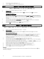
13.
Changing a Partition
To change partitions the keypad must be assigned to access the required partition.
1.
2.
3.
Hold [MODE] until the keypad beeps.
Press [1] [*].
When prompted by the display to 'Select Partition' press [partition number] [*]
The keypads may be partitioned to remain in the new partition. Any value outside of these constraints will
result in a key entry error occurring.
Feature
Partition
Zone
Output
Doors
14.
IDS 816
1 -2
1 - 16
1-7
0
IDS 1224
1 -4
1 - 24
1 - 10
0
IDS 1632
1-8
1 -32
1 - 12
1 - 14
Remote Telephone Access
Please note that this section is only relevant if programmed by your installer.
The IDS Alarm Panels have a secure, remote telephone interface which allows a user to arm/disarm, to
bypass/un-bypass zones and to set programmable outputs via a phone line. A user accesses the remote
dial-in interface by dialling the Alarm Panel using a DTMF phone.
To access the remote dial-in interface, dial the Alarm Panel, and wait the number of rings programmed
(the default number of rings being 15). If the fax defeat function has been enabled, dial the panel and
hang up after one ring. Dial in again within 1 minute, the panel will pick up immediately and transmit
handshake tones consisting of a high pitch tone for two seconds followed by a lower pitch tone for one
second.
Within twenty seconds of the panel transmitting the handshake tones, enter a valid user code on the
DTMF enabled phone. If a user code is not entered or if the user code is invalid - the panel will release
the line. If the user code is valid and telephone access has been enabled, the panel will give a single
confirmation beep indicating that the user has gained access to the remote interface. If no key-presses
are detected for twenty seconds once access has been gained to the remote interface the panel will
release the line.
Should the panel be programmed to report to your cellular telephone, entering the user code in the delay
between beeps will also allow access to the remote telephone interface.
If the phone in access has been setup to arm/disarm only, pressing the number of the partition allows the
user to toggle the panels arm status.
A single beep indicates that the partition has armed; a double beep indicates that the partition has
disarmed. 3 beeps indicate that the partition is not ready to arm.
If the phone in access has been set up to access the full menu, please refer to the table 5 and select the
required operation.
28
IDS LCD Keypad User Manual 700-292-01C Issued March 2009
Table 6 : Remote Telephone Operation
Operation
Arm a Partition
Key Entry
[1] [1] [PARTITION] [*]
Disarm a Partition
[1] [2] [PARTITION] [*]
Check Arm Status
(By Partition)
[1] [3] [PARTITION] [*]
Bypass a Zone
[2] [1] [ZONE] [*]
Un-Bypass a
Zone
[2] [2] [ZONE] [*]
Check Zone
Bypass Status
[2] [3] [ZONE] [*]
Set
Programmable
Output
3] [1] [OUTPUT] [*]
Clear
Programmable
Output
[3] [2] [OUTPUT] [*]
Test
Programmable
Output Status
[3] [3] [OUTPUT] [*]
Open Doors
[4] [1] [DOOR NO] [*]
Hang-Up
[0]
Panel Response
A Single Confirmation Beep indicates Partition armed
successfully
Three Error Beeps indicates Partition cannot be armed by
user code or Partition not ready to be armed or a key
entry error has occurred
A Single Confirmation Beep indicates Partition disarmed
successfully
Three Error Beeps indicates Partition cannot be disarmed
by user code or a key entry error has occurred
A Single Beep indicates Partition is Armed
A Double Beep indicates partition is Disarmed
Three Error Beeps indicates a key entry error
A Single Confirmation Beep indicates that the zone was
successfully bypassed
Three Error Beeps indicates that the zone cannot by
bypassed or a key entry error has occurred
Single Confirmation Beep indicates that the zone was
successfully un-bypassed
Three Error Beeps indicates that a key entry error has
occurred
A Single Beep indicates that the zone is bypassed
A Double Beep indicates that the zone is un-bypassed
Three Error Beeps indicates that a key entry error has
occurred
A Single Confirmation Beep indicates that the
programmable output was set
Three Error Beeps indicates that a key entry error has
occurs
A Single Confirmation Beep indicates that the
programmable output is clear
Three Error Beeps indicates that a key entry error has
occurred
A single Beep indicates that the programmable output is
set
A Double Beep indicates that the programmable output is
clear
Three Error Beeps indicates that a key entry error has
occurred
A Single Beep indicates that the door has been opened
A Double Beep indicates that the door has not been
opened
Three Error Beeps indicates that a key / access reader
entry error has occurred
Telephone Line Released
Three Error Beeps indicates that a key entry error has
occurred
29
IDS LCD Keypad User Manual 700-292-01C Issued March 2009
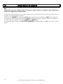
15.
Output Control via a Keypad
NB:
Ensure that you have checked with your installer which outputs are used for radio reporting to
prevent the triggering of false alarms.
If the panel has been setup to control switching functions via its outputs, these can be controlled via the
keypad - e.g. turning lights on and off.
Hold down the [MODE] key and press [3] [*]. Any outputs that are currently set [ON] will be displayed
as 'Output No. Set' any outputs that are set [OFF] will be displayed as 'Output No. Clear'. One is able to
scroll through the Outputs by using the [PANIC] and [MED] keys.
To toggle the output status, enter [OUTPUT NUMBER] followed by [*]. Press [#] to exit User Program
Mode.
30
IDS LCD Keypad User Manual 700-292-01C Issued March 2009
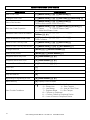
Quick Reference User Guide
Description
Programming
Add a User Code
[*] [Master Code] [*] [0] [*] [New Code] [*]
Change a User Code
[*] [Master Code] [*] [2] [*] [Old Code] [*] [New Code] [*]
View a Slot Number
[*] [Master Code] [*] [3] [*] [User Code] [*]
View the Slot number via the zone LED‟s
Edit User Code Properties
[*] [Master Code] [*] [4] [*] [User Code] [*] [2,3 or 4] [*]
2 = Duress
3 = Arm to Disarm Code
4 = Global Arm/Disarm Code
Allocate a User Code to a Partition
[*] [Master Code] [*] [5] [*] [User Code] [*] [Partition
Number] [*] [#]
Teach a Remote to a User Code
[*] [Master Code] [*] [8] [*] [User Code] [*]
Press Tx Button
Delete a User Code by Code
[*] [Master Code] [*] [9] [*] [User Code] [*]
Delete a User Code by Slot Number
[*] [Master Code] [*] [10] [*] [Slot Number] [*]
Change Partitions
[Mode] [1] [*] [Partition Number] [*]
Select a Stay Profile
[Mode] [2] [*] [Profile Number] [*]
Program/Cancel Stay Zone
[3] [Zone Number] [*] [#]
Program/Cancel Buzz Zone
[4] [Zone Number] [*] [#]
Program/Cancel Chime Zone
[2] [Zone Number] [*] [#]
Quick Arm
[1]
Quick Stay
[5]
Stay Arm and Go
[6]
Bypassing/Un-bypassing a Zone
[9] [Zone Number] [*] [#]
Alarm Memory
[0] Displays zones violated.
[7]
View Trouble Conditions
1 = AC Mains Fail
2 = No Communication
3 = Phone Line
4 = Siren Tamper
5 = Low Battery
6 = Loss of Clock Timer
7 = Engineer Reset
8 = Box Tamper
10 = Tamper on Peripheral
11 = Comms. Failure to Peripheral Device
12 = Loss of Power to Peripheral Device
31
IDS LCD Keypad User Manual 700-292-01C Issued March 2009
32
IDS LCD Keypad User Manual 700-292-01C Issued March 2009