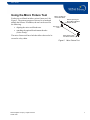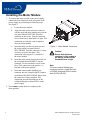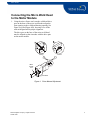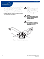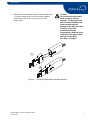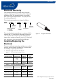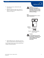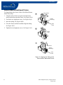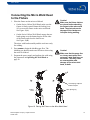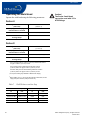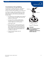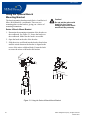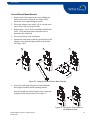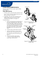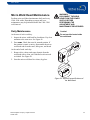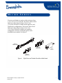
1
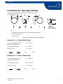
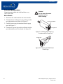
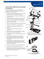
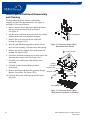
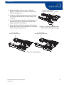
W IE L
S YE SRT EI M
M
C DRI N
OG S
E S
C
The micro weld heads are used to weld work pieces from
1/16 to 1/2 in. (3 to 12 mm) OD. The Series 4 Micro Weld
Head can weld work pieces from 1/16 to 1/4 in.
(3 to 6 mm) OD and is available in both rigid-drive and
flexible-drive configurations. The Series 8 Micro Weld
Head can weld work pieces from 1/8 to 1/2 in.
(5 to 12 mm) OD and is available in a rigid-drive
configuration. All micro weld heads operate with a
detachable motor module. See Figure 1.
Series 4
Flexible Drive
Series 8
Rigid Drive
Motor
Module
Series 4
Rigid Drive
Figure 1
Rigid-Drive and Flexible-Drive Micro Weld Heads
©2001 Swagelok Company, all rights reserved
October 2001
1
Micro Series
This manual presents information that is specific to the
micro weld heads. Additional handling is necessary
because the motor module and weld head are separate
units. The micro weld head fixtures do not use separate
collets, so fixture setup differs slightly from the Series
5/10/20 fixture block procedures.
The procedures, unless noted, are the same for all micro
weld heads. Most figures in this section show the Series 4
Rigid-Drive Micro Weld Head.
Refer to the Power Supply manual for information on
power supply setup and weld procedure guidelines.
This manual includes:
2
•
using the micro fixture tool
•
installing the motor module
•
connecting the micro weld head to the motor
module
•
installing/replacing the electrode
•
electrode geometry
•
calculating the arc gap gage settings
•
setting the arc gap
•
fixturing the work
•
connecting the micro weld head to the fixture
•
considerations during welding
•
using the optional bench mounting bracket
•
fixture block maintenance
•
micro weld head maintenance
•
parts drawings.
©2001 Swagelok Company, all rights reserved
October 2001
Micro Series
Using the Micro Fixture Tool
Each micro weld head includes a micro fixture tool. See
Figure 2. The primary purpose of the tool is to latch and
unlatch the fixtures. In addition, the tool can be used for
the following:
•
aligning the micro weld head rotor
•
attaching the optional bench mount bracket
(Series 8 only).
The micro fixture tool has a hole that allows the tool to be
secured to a key chain.
Tabs to engage the
Rotor Drive Gear
Wrench Opening for
Bench Mount Bracket
Adapter Screws
Key Chain
Hole
Slots Used to Open
and Close Fixtures
Figure 2
©2001 Swagelok Company, all rights reserved
October 2001
Micro Fixture Tool
3
Micro Series
Installing the Motor Module
1. To connect the motor module to the power supply,
connect the four connectors to the rear panel of the
power supply by performing the following steps.
See Figure 3.
a.
Locate the motor module.
b.
Align the notch on the multi-pin connector
with the small tab in the mating socket on the
rear panel labeled FIXTURE. Insert the
connector in the socket. Turn the connector
sleeve clockwise by hand until it is tight. This
connection provides the control signals to
drive the motor module.
c.
Insert and fully seat the red connector into
the socket on the rear panel labeled
ELECTRODE. Twist the connector 1/4-turn
clockwise to lock it into place. This
connection is the negative (-) terminal of
the motor module.
d.
e.
Insert the green connector into the socket on
the rear panel labeled WORK. Twist the
connector 1/4-turn clockwise to lock it into
place. This connection is the positive (+)
terminal of the motor module.
Insert the motor module shielding gas
connector into the Swagelok Quick-Connect
stem labeled TO WELD HEAD. Ensure that
the connector is firmly attached. This
connection provides shielding gas to the
weld head through a solenoid valve in the
power supply.
Figure 3
Motor Module Connectors
Caution!
Ensure that the fixture
connector is fully seated in
the mating socket and the
threaded sleeve is tight.
Note:
The motor module shielding gas
connector must be a single-end shutoff (SESO) Swagelok Quick-Connect
stem (SS-QC4-S-400).
2. Press HOME to return the drive coupling to the
home position.
4
©2001 Swagelok Company, all rights reserved
October 2001
Micro Series
Connecting the Micro Weld Head
to the Motor Module
1. Using the micro fixture tool, turn the weld head drive
gear on the base of the micro weld head to align the
rotor opening to the weld head housing opening. See
Figure 4(A) and Figure 4(B), showing views of the
rotor misaligned and in proper alignment.
The drive gear on the base of the micro weld head
must be aligned so that it meshes with the drive pins
on the motor module.
B
A
Wrong
Correct
Micro
Fixture
Tool
Drive Gear
Figure 4
©2001 Swagelok Company, all rights reserved
October 2001
Rotor Manual Adjustment
5
Micro Series
2. Locate the shielding gas port on the micro weld head
and verify that the O-ring is in place. See Figure 5.
The O-ring seals the gas port. A valve in the port
opens the gas flow through the motor module. The
valve opens when the micro weld head is properly
connected to the motor module.
3. Align the connecting surfaces of the micro weld head
and motor module. See Figure 5.
Caution!
The micro weld heads should
not be started in any rotor
position except fully homed.
See Figure 5. Arc start in any
other location may cause
weld head damage.
Caution!
Step Programs should not be
used with Series 4 or Series 8
Micro Weld Heads.
Caution!
Tack programs or programs
that include tacks should not
be used with the micro
weld heads.
Valve
O-ring
Mating Connections
Figure 5
6
O-ring and Mating Connections
©2001 Swagelok Company, all rights reserved
October 2001
Micro Series
4. Push the micro weld head onto the motor module until
it is firmly seated, then lock the assembly together
with the two side latches. See Figure 6(A) and
Figure 6(B).
Caution!
Do not force the micro weld
head and motor module
together. The drive gears of
the micro weld head and the
motor module must be
aligned for the pieces to mate
correctly. If you have
problems mating the
components, rotate the micro
weld head drive gear a small
amount and try again.
See Step 1 on page 5.
A
B
Figure 6
©2001 Swagelok Company, all rights reserved
October 2001
Connecting Weld Head and Motor Module
7
Micro Series
Electrode Geometry
This illustration shows the electrode shape Swagelok
suggests. Properly ground electrodes provide consistent,
repeatable welds. Pre-ground electrodes are available
from your Swagelok representative. See your parts list
for ordering information.
The electrode part numbers are assigned as follows:
SWS – X.###
-
#.###
- ###
-
Electrode
Diameter
Material Designator
C = Ceriated
T = Thoriated
P
Package
Designator
Electrode
Length
Tip Diameter
The ceriated electrode material type is a mixture of 98 %
tungsten and 2 % cerium and is commonly referred to as
“2 % ceriated.” This electrode type has demonstrated
improved arc starting performance over the 2 % thoriated
type, particularly when using purified shielding gas.
Figure 7
Tungsten Electrode
Installing/Replacing the
Electrode
The micro weld head tool package includes a screwdriver,
tweezers, and an electrode cleaning tool. Use these tools
for installing or replacing the electrode.
1. Select the proper electrode for the job.
Table 1
Series 4 Electrode Selection
Electrode Part No.
Component OD
CWS-C.040-.405-P
1/8 in.
1/16 in.
3 mm
1/4 in.
6 mm
CWS-C.040-.325-P
Table 2
Electrode
Diameter
(D)
0.405 in.
(10,29 mm)
0.040 in.
(1,02 mm)
0.325 in.
(8,26 mm)
0.040 in.
(1,02 mm)
Series 8 Electrode Selection
Electrode Part No.
Component OD
Electrode
Length (L)
CWS-C.040-.405-P
1/4 in.
6 to 8 mm
3/8 in.
10 mm
1/2 in.
12 mm
0.405 in.
(10,29 mm)
0.325 in.
(8,26 mm)
0.281 in.
(7,14 mm)
CWS-C.040-.325-P
CWS-C.040-.281-P
8
Electrode
Length (L)
Electrode
Diameter
(D)
0.040 in.
(1,02 mm)
0.040 in.
(1,02 mm)
0.040 in.
(1,02 mm)
©2001 Swagelok Company, all rights reserved
October 2001
Micro Series
2. Disconnect the micro weld head from the
motor module.
3. Manually turn the rotor drive gear, shown in
Figure 4, until the electrode clamping screw is
exposed. See Figure 8.
Caution!
Only ceriated tungsten
should be used in the micro
weld heads. The use of other
types of tungsten may cause
weld head damage.
Note:
Replace the electrode when it shows
signs of deterioration.
Electrode
Clamping
Screw
Figure 8
Electrode Clamping
Screw Location
Caution!
Do not rotate the rotor with
the electrode clamping screw
loose. Damage to the micro
weld head housing
may result.
4. While holding the micro weld head as shown in
Figure 9(A), loosen the electrode clamping screw.
This orientation helps to prevent the electrode from
falling out during installation.
©2001 Swagelok Company, all rights reserved
October 2001
9
Micro Series
5. Install a new electrode using tweezers. Insert the
electrode through the ceramic insulator and into the
rotor to its full insertion depth. Make sure the sharp tip
of the electrode is pointing out. See Figure 9(B).
6. Tighten the clamping screw sufficiently to prevent the
electrode from falling out of the rotor. Do not
over tighten the clamping screw.
Note:
Clean the electrode before every weld
for optimum performance.
A
B
Figure 9
10
Installing the Electrode
©2001 Swagelok Company, all rights reserved
October 2001
Micro Series
Calculating Arc Gap Gage Settings
To determine the arc gap gage setting for a specific arc gap,
use the formula below.
A
B
A
2
C
B
2
C
ARC GAP
GAGE
SETTINGS
Where
A = largest OD on the weld end of the tubing or fitting (welding diameter)
B = arc gap gage diameter
C = desired arc gap
Figure 10 Arc Gap Gage Setting Formula
Example No. 1: (Series 4 Weld Head)
1/8 to 1/8 in. tube butt weld –
largest outside diameter
A = 0.125 in.
Arc gap gage diameter
B = 0.620 in.
Desired arc gap
C = 0.03 in.
0.125 in.
2
+
0.620 in.
2
+
0.03 in.
=
0.4025 in.
Example No. 2: (Series 4 Weld Head)
6 to 6 mm tube butt weld –
largest outside diameter
A = 6,00 mm
Arc gap gage diameter
B = 15,75 mm
Desired arc gap
C = 0,64 mm
6,00 mm
2
+
15,75 mm
2
+
0,64 mm
©2001 Swagelok Company, all rights reserved
October 2001
=
11,515 mm
11
Micro Series
Setting the Arc Gap
The micro weld head also includes an arc gap gage,
which is required to set the arc gap. The gage fits the
rotor aperture and adjusts for the desired arc gap.
A
1. Measure the OD of the work to be welded with a
caliper or micrometer and record the value.
See Figure 11(A).
2. Locate the OD value in the following table that
matches the OD of the work. Find the arc gap gage
setting listed for that OD and record it.
B
Figure 11 Setting Arc Gap Gage
12
©2001 Swagelok Company, all rights reserved
October 2001
Micro Series
Table 3
Nominal
OD (in.)
1/16
1/8
1/4
SWS-4MRH-B, SWS-4MFH-B Arc Gap Gage Dia. 0.620 in.
Actual
OD
(in.)
0.062
0.125
0.250
Table 4
Setting
for
0.025 in.
Arc Gap
(in.)
0.366
0.398
0.461
Setting
for
0.030 in.
Arc Gap
(in.)
0.371
0.403
0.466
Setting
for
0,51mm
Arc Gap
(mm)
9,19
9,99
11,58
Setting
for
0,64mm
Arc Gap
(mm)
9,32
10,12
11,71
Setting
for
0,76mm
Arc Gap
(mm)
9,44
10,24
11,83
SWS-4MRH-B, SWS-4MFH-B Arc Gap Gage Dia. 15,75 mm
Nominal OD
(mm)
3
6
Table 5
Nominal
OD (in.)
1/8
1/4
3/8
1/2
Setting
for
0.020 in.
Arc Gap
(in.)
0.361
0.393
0.456
Setting for
0,51 mm Arc
Gap (mm)
9,91
11,41
Actual OD
(mm)
3,00
6,00
Setting for
0,64mm Arc
Gap (mm)
10,04
11,54
Setting for
0,76mm Arc
Gap (mm)
10,16
11,66
SWS-8MRH-B Arc Gap Gage Dia. 0.813 in.
Actual
OD
(in.)
0.125
0.250
0.375
0.500
Table 6
Nominal OD
(mm)
6
8
10
12
Setting
for
0.020 in.
Arc Gap
(in.)
0.490
0.552
0.614
0.677
Setting
for
0.025 in.
Arc Gap
(in.)
0.495
0.557
0.619
0.682
Setting
for
0.030 in.
Arc Gap
(in.)
0.500
0.562
0.624
0.687
Setting
for
0.035 in.
Arc Gap
(in.)
N/A
0.567
0.629
0.692
Setting
for
0,51mm
Arc Gap
(mm)
12,45
14,02
15,60
17,20
Setting
for
0,64mm
Arc Gap
(mm)
12,57
14,15
15,73
17,33
Setting
for
0,77mm
Arc Gap
(mm)
12,70
14,28
15,86
17,46
Setting
for
0,89 mm
Arc Gap
(mm)
N/A
14,40
15,98
17,58
SWS-8MRH-B Arc Gap Gage Dia. 20,65 mm
Actual OD
(mm)
6,00
8,00
10,00
12,00
Setting for
0,51 mm Arc
Gap (mm)
13,84
14,84
15,84
16,84
Setting for
0,64mm Arc
Gap (mm)
13,97
14,97
15,97
16,97
Setting for
0,76mm Arc
Gap (mm)
14,09
15,09
16,09
17,09
Setting for
0,89 mm Arc
Gap (mm)
14,22
15,22
16,22
17,22
3. Set the arc gap gage to the value from the table using
the provided 3/32 in. hex wrench. Measure from the
bottom of the arc gap gage to the top of the adjustment
screw. See Figure 11(B).
4. Insert the arc gap gage into the micro weld head
rotor opening.
©2001 Swagelok Company, all rights reserved
October 2001
13
Micro Series
5. Hold the micro weld head so that the electrode tip is
pointing down. Loosen the electrode clamping screw
to allow the electrode to fall against the arc gap gage.
See Figure 12.
6. Tighten the electrode clamping screw to hold the
electrode in place. Do not over tighten. Remove the
arc gap gage.
The rotor may move due to the torque of tightening
the clamping screw. Use your finger to hold the rotor
in place.
7. Attach it to the motor module. Complete the steps in
Connecting the Micro Weld Head to the Motor
Module beginning on page 5. When complete,
proceed with step 8.
Figure 12 Setting the Arc Gap
8. Press HOME to return the rotor to the home position.
14
©2001 Swagelok Company, all rights reserved
October 2001
Micro Series
Fixturing the Work
The work pieces must be properly prepared
before fixturing.
1. Locate the centering gage. Turn the gage so the
labeled side faces the part to be installed first. Insert
the gage into the fixture. See Figure 13.
2. Open the fixture side facing the labeled side of
the centering gage by rotating the latch 90°.
See Figure 14.
The fixture opens with a scissors type action.
Figure 14 shows how to use the micro fixture tool
on the Series 4 fixture.
Figure 13 Inserting Centering Gage
Centering Gage Label
Towards Part
Opening
the Fixture
Note: Use the micro fixture tool
for Series 4 and Series 8
Figure 14 Insert First Work Piece
©2001 Swagelok Company, all rights reserved
October 2001
15
Micro Series
Caution!
3. Insert the first work piece, butting the weld end
against the centering gage surface. Close and latch
that side of the fixture. Make sure that the latch is
fully closed against the body of the fixture.
See Figure 15.
When closing the fixture, be
sure the moving side of the
fixture engages into the small
groove on the stationary side
of the fixture.
4. Remove the centering gage.
5. Open the other side of the fixture and insert the
second work piece. Butt the weld ends together. Close
and latch that side.
6. Check the weld joint for proper fit and alignment. See
Figure 15. Verify that the latches are fully closed. See
Figure 15 (Series 4) or Figure 16 (Series 8).
7. Connect the purge gas line to the work pieces. Refer
to the Purge Gas Delivery System section in the
Power Supply manual.
8. Open the shut-off valve in the purge gas line.
9. Set the flow meters according to the weld procedure
guideline for both the shielding and internal purge gas.
The length of time for internal purge before welding
depends on the internal volume and length of the work
piece to be welded. Refer to the Gas Flow Rate
Tables in the Power Supply manual.
Correct
Wrong
Figure 15 Checking the Weld Joint and
Latch Position (Series 4 Fixture)
Correct
Wrong
Figure 16 Proper Latch Position
(Series 8 Fixture)
16
©2001 Swagelok Company, all rights reserved
October 2001
Micro Series
Aligning the Work Pieces
Series 4 Micro Weld Head Fixture
Open Fixture
A
To align tubing in the Series 4 Micro Weld Head Fixture,
follow these steps:
1. Using the micro fixture tool, place the latch in the
open position then open the fixture. See Figure 17(A).
2. Loosen the two alignment screws. See Figure 17(A).
Loosen
Screw
3. Insert the tubing. See Figure 17(B).
4. Close the fixture and latch and then align the tubing.
See Figure 17(C).
Open
Latch
Loosen
Screw
B
5. Tighten the two alignment screws. See Figure 17(C).
Insert
Tube
C
Close Fixture
Tighten
Screw
Close
Latch
Tighten
Screw
Figure 17 Aligning the Tubing in the
Series 4 Micro Weld Head Fixture
©2001 Swagelok Company, all rights reserved
October 2001
17
Micro Series
Series 8 Micro Weld Head Fixture
To align tubing in the Series 8 Micro Weld Head Fixture,
follow these steps:
A
Open Fixture
1. Using the micro fixture tool, place the latch in the
open position then open the fixture. See Figure 18(A).
Loosen
Screws (2)
2. Loosen the two alignment screws. See Figure 18(A).
3. Insert the tubing. See Figure 18(B).
Open
Latch
4. Close the fixture and latch and then align the tubing.
See Figure 18(C).
5. Tighten the two alignment screws. See Figure 18(C).
B
Insert
Tube
C
Close Fixture
Tighten
Screws (2)
Close
Latch
Figure 18 Aligning the Tubing in the
Series 8 Micro Weld Head Fixture
18
©2001 Swagelok Company, all rights reserved
October 2001
Micro Series
Connecting the Micro Weld Head
to the Fixture
Caution!
1. Place the fixture on the micro weld head.
•
On the Series 4 Micro Weld Head, make sure the
fixture is firmly seated. Rotate the locking lever
90° to secure the fixture to the micro weld head.
See Figure 19(A).
•
On the Series 8 Micro Weld Head, engage the two
latch springs over the button keepers on the sides
of the fixture and close the latch levers.
See Figure 19(B).
Make sure the fixture latches
are closed before attaching
the fixture to the micro weld
head. The electrode can be
damaged if the latches are
left open during welding.
The micro weld head assembly and the work are ready
for welding.
2. Press PURGE to begin the shielding gas flow. The
shielding gas should remain on at all times when using
the micro weld head.
Caution!
Make sure that the purge line
or a heavy work piece does
not exert a side load force on
the fixture. This may cause
an unacceptable weld,
damage to the micro weld
head, or both.
3. Program the power supply and perform the weld using
the parameters in Operating the Weld Head on
page 20.
A
B
Latch Spring Captures
Button Keepers
Locking
Lever
Latch Springs (2)
Figure 19 Placing the Fixture on the Micro Weld Head
©2001 Swagelok Company, all rights reserved
October 2001
19
Micro Series
Operating the Weld Head
Caution!
Operate the weld head using the following parameters:
The Series 8 weld head
can not be used with 1/2 in.
ATW fittings.
Series 4
Shield gas flow rate std ft3/hr
(std L/min)
8 to 10
(3,8 to 4,7)
Prepurge and Postpurge
minimum time in seconds
Continuous
Start Power
U-low, Low, Norm①
Maximum Recommended
Average Amps
30A
Series 8
Shield gas flow rate std ft3/hr
(std L/min)
15 to 20
(7,1 to 9,4)
Prepurge and Postpurge
minimum time in seconds
Continuous
Start Power
U-low, Low, Norm①②
Maximum Recommended
Average Amps
38A③
①
Use U-low start power for 0.010 in. (0,25 mm) wall thickness and an
arc gap of 0.020 in. (0,51 mm) or less.
Use Low start power for wall thickness less than 0.030 in.
(0,76 mm) and an arc gap of 0.025 in. (0,64 mm) or less.
Use Norm start power for wall thickness greater than 0.030 in.
(0,76 mm) and an arc gap of 0.035 in. (0,89 mm) or less.
② U-low
power setting only available on M100 Power Supply.
③When
welding 1/2 in. or 12 mm OD with a Series 8 weld head, use the
single pass (one revolution) weld procedure only.
Table 7
Wall Thickness and Arc Gap
Material Thickness (mm)
20
Arc Gap
In.
mm
In.
mm
0.010 to 0.020
0,25 to 0,51
0.020
0,51
0.021 to 0.030
0,52 to 0,76
0.025
0,64
0.031 to 0.045
0,77 to 1,14
0.030
0,76
0.046 to 0.055
1,15 to 1,40
0.035
0,89
©2001 Swagelok Company, all rights reserved
October 2001
Micro Series
Considerations During Welding
The approach to welding using the micro weld head is
similar to that used for other Swagelok weld heads.
Develop a weld procedure guideline as you would for any
job. The power supply controls and indicators work the
same. However, the unique qualities of the micro weld
head and its fixtures cause some noticeable differences
during welding:
•
The sound of the weld is slightly louder compared
to other Swagelok weld heads. This is due to the
reduced size of the fixture.
•
You may notice a clicking sound during the
downslope cycle. This is normal. The fixture
contracts slightly due to heat dissipation,
producing the sound.
•
Because the fixture is small, heat build-up may
make the device too hot to handle immediately
after welding. Hold the fixture in the base areas
shown in Figure 20. Use the optional aluminum
cooling plate to hold the fixture and allow it to
cool faster. See Figure 20.
•
Extended internal purging assists the
cooling process.
©2001 Swagelok Company, all rights reserved
October 2001
Hold Here
Hold Here
Figure 20 Cooling Plate
WARNING!
THE FIXTURE MAY BE HOT
AFTER WELDING IS
COMPLETE. USE CAUTION
WHEN HANDLING.
21
Micro Series
Using the Optional Bench
Mounting Bracket
The bench mounting brackets attach Series 4 and Series 8
Micro Weld Heads to a workbench. There are two
mounting plates on the bracket, giving you a choice of
mounting orientations.
Series 4 Bench Mount Bracket
Caution!
Do not put the micro weld
head in a vise. Severe
damage may result, which
would void any warranty.
1. Determine the mounting orientation of the bracket on
the workbench. See Figure 21. Secure the bracket to
the workbench. Make sure the latch is accessible.
2. Open the latch on the side of the bracket.
3. Slide the micro weld head into the bracket from below
until the raised detent on the bracket is aligned to the
recess of the micro weld head body. Fasten the latch
to secure the micro weld head to the bracket.
Figure 21 Using the Series 4 Bench Mount Bracket
22
©2001 Swagelok Company, all rights reserved
October 2001
Micro Series
Series 8 Bench Mount Bracket
1. Remove one of the button head screws holding the
latch bracket to the weld head. See Figure 22(A).
Insert one of the supplied adapter screws.
2. Secure the adapter screw with a 1/4 in. wrench or the
micro fixture tool. See Figure 22(B).
3. Repeat steps 1. and 2. for the remaining latch bracket
screw. Verify the latch bracket remains securely
attached to the weld head.
4. Secure the bracket to the workbench.
5. Position the weld head so that the exposed ends of the
adapter screws slide through the hole in the bracket.
See Figure 22(C).
A
B
C
Figure 22 Using the Series 8 Bench Mount Bracket
6. Secure the weld head using the two knurled thumb
nuts supplied with the bench mounting bracket.
Keep the thumb nuts on the adapter screws when not
using the bench mount bracket. See Figure 23.
Figure 23 Storing the Thumb Nuts on
the Adapter Screws
©2001 Swagelok Company, all rights reserved
October 2001
23
Micro Series
Fixture Block Maintenance
Series 8 Fixture
The micro weld head fixtures require regular cleaning
and maintenance.
Daily Maintenance
1. Clean the surfaces of the fixture that contact the work
pieces. Use the wire brush included in the micro weld
head tool package. See Figure 24.
2. If applicable, check the fixture insulating tape for
damage. Replace the tape if it is loose or torn,
exposing the metal under it. See Figure 25.
To replace the tape:
a.
Remove the damaged tape from both sides of
the fixture. Disassembly of the SWS-8MFA08 and SWS-8MFA-12MM may be necessary
to assist in replacing the tape. Disassemble by
removing the screws that hold the arc covers
on each side of the fixture. Refer to the Part
Drawings section of this manual for more
detail.
b.
Clean the surfaces with alcohol or acetone.
c.
Apply one end of the pre-cut tape strip to
the inside edge of the underside surface. The
tape should wrap in the direction shown in
Figure 25.
d.
Wrap the tape tightly (approximately
1 1/2 turns). The tape should end at the
outside edge of the top surface.
Series 4 Fixture
Clean these
surfaces
Figure 24 Cleaning the Micro Weld
Head Fixtures
Outside Edge
Inside Edge
Clean these
surfaces
Figure 25 Checking/Replacing the
Insulator Tape
24
©2001 Swagelok Company, all rights reserved
October 2001
Micro Series
Micro Weld Head Maintenance
Perform micro weld head maintenance daily and every
1200–1500 welds. Depending on usage and wear,
maintenance may be performed before the 1200–1500
weld interval.
Daily Maintenance
At the start of each work day:
1. Inspect the micro weld head for cleanliness. Pay close
attention to the rotor area. See Figure 26.
WARNING!
DISCONNECT THE WELD
HEAD FROM THE POWER
SUPPLY BEFORE
PERFORMING THE
ADJUSTMENT AND
MAINTENANCE PROCEDURES.
Caution!
Do not use lubricants inside
the weld head.
2. Press HOME. Check the rotor for smooth rotation. If
the rotation is erratic or noisy, disassemble the micro
weld head and clean the rotor, idler gears, and brush.
At the end of each work day:
1. Remove dirt, carbon, and vapor deposits from the
weld head with a clean, soft cloth and a solvent such
as alcohol. See Figure 26.
2. Store the micro weld head in a clean, dry place.
Figure 26 Inspect Exposed Surfaces of
the Weld Head
©2001 Swagelok Company, all rights reserved
October 2001
25
Micro Series
Periodic Maintenance
Clean the motor module and weld head after every
1200–1500 welds.
Motor Module
Caution!
Do not clamp the motor
module in a vise
while cleaning.
1. Disconnect the weld head from the motor module.
2. Clean the motor module power lug sockets with the
provided stainless steel brush. See Figure 27.
Power Lug Sockets
3. Carefully remove any obstructions from the purge
port. See Figure 27.
4. Clean the two power lugs on the weld head with the
provided stainless steel wire brush. See Figure 28.
Purge Port
Figure 27 Cleaning the Power Lug
Sockets and the Purge Port
Power Lugs
Figure 28 Cleaning the Weld Head
Power Lugs
26
©2001 Swagelok Company, all rights reserved
October 2001
Micro Series
Series 4 Micro Weld Head Disassembly
and Cleaning
A
Housing Screws
To disassemble the Series 4 micro weld head for
cleaning, use the following instructions. See Figure 29
and Figure 30 for part references.
1. Lay the micro weld head down on a clean, dry surface
with the model and serial numbers facing up.
Housing
Gear Side
2. Remove the five screws from the weld head housing.
See Figure 29(A).
3. Rock the gear side body gently to loosen it from the
rest of the assembly. Lift and remove the housing.
D
Idler
Gears
Electrode
4. Remove the rotor by lifting it clear of the brush side
housing. See Figure 29(B).
5. Loosen the electrode clamping screw, then remove the
electrode and ceramic insert. See Figure 29(C).
6. Clean the rotor with the provided stainless steel
wire brush.
Electrode
Screw
C
Ceramic Insert
Rotor
B
Brush
Spring
7. Clean the ceramic insert with the provided
nylon brush.
8. Remove and inspect the two idler gears for damage.
Replace if necessary. See Figure 29(D).
Housing Brush Side
9. Clean the two idler gears with isopropyl alcohol and
a soft cloth.
Figure 29 Removing Series 4 Micro
Weld Head Components for Cleaning
10. See Figure 30(A). Hold the micro weld head as
shown. Gently lift the brush from the brush side
housing noted in the figure and rotate it outward
a few degrees.
A
11. Note the position of the spring in the groove in the
weld head brush. The spring ends bend toward the
brush when the spring lays in the groove. Remove the
spring. See Figure 30(B).
12. Clean any oxide deposits from the weld head brush
with the provided stainless steel wire brush.
13. Inspect all other weld head components and clean any
that are dirty. Blow any loose dirt from the weld head
with clean, dry, low-pressure air.
B
Insert Spring so
Ends Bend
Toward Brush
Figure 30 Lifting the Weld Head
Brush for Cleaning
©2001 Swagelok Company, all rights reserved
October 2001
27
Micro Series
Series 8 Micro Weld Head Disassembly
and Cleaning
To disassemble the Series 8 micro weld head for
cleaning, use the following instructions. See Figure 31
and Figure 32 for part references.
1. Remove the two screws that secure the latch bracket
and remove the bracket from the weld head.
See Figure 31.
Latch Bracket
2. Lay the micro weld head down on a clean, dry surface
with the model and serial numbers facing up.
3. Remove the seven screws from the weld head
housing. See Figure 32(A).
Figure 31 Removing Series 8 Micro
Weld Head Latch Bracket
4. Rock the gear side housing gently to loosen it from
the rest of the assembly. Lift and remove the housing.
5. Remove the rotor by lifting it clear of the brush side
housing. See Figure 32(B).
A
Housing Screws
6. Loosen the electrode clamping screw, then remove the
electrode and ceramic insert. See Figure 32(C).
7. Clean the rotor with the provided stainless steel
wire brush.
8. Clean the ceramic insert with the provided
nylon brush.
Housing
Gear Side
Ceramic Insert
9. Remove and inspect the four idler gears for damage.
Replace if necessary. See Figure 32(D).
Electrode
10. Clean the idler gears with isopropyl alcohol and a
soft cloth.
Electrode
Screw
Rotor
C
Idler
Gears D
B
Housing Brush Side
Figure 32 Removing Series 8 Micro
Weld Head Components for Cleaning
28
©2001 Swagelok Company, all rights reserved
October 2001
Micro Series
11. Replace the idler gears in the micro weld head
housing. Verify the idler gear axles are pressed into
the body. See Figure 33.
Correct Idler Gear Placement
(Pressed Fully into Body)
Incorrect
12. Clean any oxide deposits from the exposed surface of
the weld head brush with the provided stainless steel
wire brush.
13. Verify that the spring under the weld head brush is not
exposed. See Figure 34. If necessary reposition the
spring under the weld head brush.
14. Inspect all other weld head components and clean any
that are dirty. Blow any loose dirt from the weld head
with clean, dry, low-pressure air.
Correct Position
(Spring Covered by Brush)
Figure 33 Correct Placement of Idler
Gears in Micro Weld Head Housing
Incorrect Position
(Spring Exposed Under Brush)
Figure 34 Spring Position
©2001 Swagelok Company, all rights reserved
October 2001
29
Micro Series
30
©2001 Swagelok Company, all rights reserved
October 2001
Micro Series
Parts Drawings
This section includes exploded assembly drawings and
associated parts lists. These drawings are provided as a
guide to identifying part names. For specific part ordering
information, contact your Swagelok representative.
The parts identified in this section include:
•
SWS-M-MTR-B Motor Module
•
SWS-4MRH-B Rigid Weld Head
•
SWS-4MFH-B Flexible Weld Head
•
SWS-4MFB-XX Fixture
•
SWS-8MRH-B Rigid Weld Head
•
SWS-8MFA-XX Fixture
©2001 Swagelok Company, all rights reserved
October 2001
31
Micro Series
Figure 35 SWS-M-MTR-B Motor Module
32
©2001 Swagelok Company, all rights reserved
October 2001
Micro Series
Table 8
SWS-M-MTR-B Motor Module Parts List
Reference
Description
No.
1
Motor Module Cover (Brush Side)
2
SS Button Head Cap Screw, 4-40 x 0.250 in.
3
Latch
4
Motor Module Cover (Gear Side)
5
SS Socket Head Cap Screw, 4-40 x 0.250 in.
For part ordering information, contact your Swagelok representative.
©2001 Swagelok Company, all rights reserved
October 2001
Part No.
10011
13167
11434
11427
13112
Minimum
Order Quantity
1
10
1
1
10
33
Micro Series
23
22
21
20
19
18
17
17
16
16
27
28
26
15
30
15
24
29
15
25
14
1
13
12
2
11 10
9
8
7
6
5
4
3
Figure 36 SWS-4MRH-B Rigid Weld Head
34
©2001 Swagelok Company, all rights reserved
October 2001
Micro Series
Table 9
SWS-4MRH-B Rigid Weld Head Parts List
Reference
No.
Description
1
Housing (Brush Side)①
2
3
4
5
6
7
8
Work Pin
Brush Spring
Brush
Rotor
See Electrode Chart
Ceramic Insert
SS Round Head Screw,
2-56 x 0.125 in., modified
Gear Assembly
Transmission
SS Dowel Pin, 0.093 x 0.375 in.
Locking Lever
Plastic Flat Head Screw,
4-40 x 0.313 in.
9
10
11
12
13
Part No.
21160
Minimum
Order Quantity
1
11412
11405
11404-A
11403-A
N/A
11446
13158
1
1
1
1
N/A
1
1
10009-1
11447
13211
11435
13157
1
1
10
1
1
14
Housing (Gear Side)②
21159
1
15
SS Socket Head Cap Screw,
4-40 x 0.250 in.
SS Button Head Cap Screw,
4-40 x 0.250 in.
Latch Keeper
Interface Cover (Gear Side)
Purge Gas Tubing
Plastic Drive Shaft Sleeve
13112
10
13167
10
13197
11422
10010-2
09999
21241
10
1
1
10
1
11411
11424
10007
13159
11414
11425
13202
13220
11448
1
1
1
10
1
1
1
10
1
16
17
18
19
20
21
Interface Assembly (Rigid)③
22
Pinion Gear Bearing
23
Drive Coupling Gear
24
Interface Cover (Brush Side)
25
SS Round Head Screw, 2-56 x 0.125 in.
26
Solid Drive Coupling
27
Drive Shaft
28
Drive Spring Clip
29
SS #2 Internal Star Washer
30
Coupling Collar
For part ordering information, contact your Swagelok representative.
① Use
Part Number 11401-A for the CWS-4MRH-A
② Use
Part Number 11402-A for the CWS-4MRH-A
③ Use
Part Number 10456 for the CWS-4MRH-A
©2001 Swagelok Company, all rights reserved
October 2001
35
Micro Series
24
23
22
21
20
19
19
20
16
15
29
15
25
18
17
28
15
16
15
27 26
14
1
13
12
2
11 10
9
8
7
6
5
4
3
Figure 37 SWS-4MFH-B Flexible Weld Head
36
©2001 Swagelok Company, all rights reserved
October 2001
Micro Series
Table 10 SWS-4MFH-B Flexible Weld Head Parts List
Reference
No.
1
Description
Housing (Brush Side)①
2
3
4
5
6
7
8
9
10
11
12
13
14
Work Pin
Brush Spring
Brush
Rotor
See Electrode Chart
Ceramic Insert
SS Round Head Screw, 2-56 x 0.125 in., modified
Gear Assembly
Transmission
SS Dowel Pin, 0.093 x 0.375 in.
Locking Lever
Plastic Flat Head Screw, 4-40 x 0.313 in.
15
16
17
18
19
20
21
22
SS Socket Head Cap Screw, 4-40 x 0.250 in.
Drive Spring Clip
Purge Gas Tubing
Flexible Tube Assembly
SS Button Head Cap Screw, 4-40 x 0.250 in.
Latch Keeper
Interface Cover (Gear Side)
Housing (Gear Side)②
Interface Assembly (Flex)③
23
Pinion Gear Bearing
24
Drive Coupling Gear
25
Interface Cover (Brush Side)
26
SS #2 Internal Star Washer
27
SS Round Head Screw, 2-56 x 0.125 in.
28
Coupling Collar
29
Flexible Drive Shaft
For part ordering information, contact your Swagelok representative.
① Use
Part Number 11401-A for the CWS-4MFH-A
② Use
Part Number 11402-A for the CWS-4MFH-A
③ Use
Part Number 10455 for the CWS-4MFH-A
©2001 Swagelok Company, all rights reserved
October 2001
Part No.
21160
Minimum
Order Quantity
1
11412
11405
11404-A
11403-A
N/A
11446
13158
10009-1
11447
13211
11435
13157
21159
1
1
1
1
N/A
1
1
1
1
10
1
1
1
13112
13202
10010-1
11415
13167
13197
11422
21240
10
1
1
1
10
10
1
1
11411
11424
10007
13220
13159
11448
11419
1
1
1
10
10
1
1
37
Micro Series
6
4
5
7
1
12
11
2
3
9
2
10
4
9
8
5
7
6
Figure 38 SWS-4MFB-XX Fixture
38
©2001 Swagelok Company, all rights reserved
October 2001
Micro Series
Table 11 SWS-4MFB-XX Fixture Parts List
Reference
Description
No.
1
Latch Cam (Right)
2
SS Socket Head Cap Screw, 4-40 x 0.313 in.
3
Latch Cam (Left)
4
SS Shoulder Screw, 4-40
5
SS #4 Washer, 0.312 in.
6
SS Binding Screw, 4-40 x 0.188 in.
7
SS Disk Spring, 0.230 x 0.322 in.
8
1/16 in. Moveable Side Plate (Left)
8
1/8 in. Moveable Side Plate (Left)
8
3/16 in. Moveable Side Plate (Left)
8
1/4 in. Moveable Side Plate (Left)
8
2 mm Moveable Side Plate (Left)
8
3 mm Moveable Side Plate (Left)
8
4 mm Moveable Side Plate (Left)
8
6 mm Moveable Side Plate (Left)
9
Non-Conductive Tape
10
1/16 in. Fixed Side Plate (Right)
10
1/8 in. Fixed Side Plate (Right)
10
3/16 in. Fixed Side Plate (Right)
10
1/4 in. Fixed Side Plate (Right)
10
2 mm Fixed Side Plate (Right)
10
3 mm Fixed Side Plate (Right)
10
4 mm Fixed Side Plate (Right)
10
6 mm Fixed Side Plate (Right)
11
1/16 in. Fixed Side Plate (Left)
11
1/8 in. Fixed Side Plate (Left)
11
3/16 in. Fixed Side Plate (Left)
11
1/4 in. Fixed Side Plate (Left)
11
2 mm Fixed Side Plate (Left)
11
3 mm Fixed Side Plate (Left)
11
4 mm Fixed Side Plate (Left)
11
6 mm Fixed Side Plate (Left)
12
1/16 in. Moveable Side Plate (Right)
12
1/8 in. Moveable Side Plate (Right)
12
3/16 in. Moveable Side Plate (Right)
12
1/4 in. Moveable Side Plate (Right)
12
2 mm Moveable Side Plate (Right)
12
3 mm Moveable Side Plate (Right)
12
4 mm Moveable Side Plate (Right)
12
6 mm Moveable Side Plate (Right)
For part ordering information contact your Swagelok representative.
©2001 Swagelok Company, all rights reserved
October 2001
Part No.
12045-B
13320
12044-B
13286
13285
13287
13319
20716
20717
20718
20719
20720
20721
20723
20724
14098
20707
20708
20709
20710
20711
20712
20714
20715
20698
20699
20700
20701
20702
20703
20705
20706
20725
20726
20727
20728
20729
20730
20732
20733
Minimum
Order Quantity
1
10
1
10
10
10
10
1
1
1
1
1
1
1
1
10
1
1
1
1
1
1
1
1
1
1
1
1
1
1
1
1
1
1
1
1
1
1
1
1
39
Micro Series
30
29
28
25
23
26 27
31
22
21
21
24
20
22
19
34
26
18
33
20
35
25
38
36
17
32
37
1
16
2
8
2
12 11 10
7
6
5
3
4
9
15
14
13
Figure 39 SWS-8MRH-B Rigid Weld Head
40
©2001 Swagelok Company, all rights reserved
October 2001
Micro Series
Table 12 SWS-8MRH-B Rigid Weld Head Parts List
Reference
No.
1
Description
Housing (Brush Side, Bottom)①
21158
Minimum
Order Quantity
1
2
3
4
5
6
7
8
9
10
11
12
13
14
15
16
17
18
SS Socket Head Cap Screw, 2-56 x 0.250in.
Housing (Brush Side, Top)
Brush Spring
Brush
Transmission
Gear Assembly
Dowel Pin (Included with 11515)
Rotor
See Electrode Chart
SS Round Head Screw, 2-56 x 0.125 in., modified
Ceramic Insert
Latch
Latch Bracket
Plastic Flat Head Screw, 4-40 x 0.313 in.
Housing (Gear Side, Top)
SS Socket Head Cap Screw, 4-40 x 0.812 in.
13176
11523
11510
11506
11503
11515
N/A
11502
N/A
13158
11505
11520
11519
13309
11524
13161
21157
10
1
1
1
1
1
N/A
1
N/A
1
1
1
1
1
1
10
1
19
20
21
22
23
24
25
26
27
28
SS Socket Head Cap Screw, 4-40 x 0.375 in.
SS Socket Head Cap Screw, 4-40 x 0.250 in.
SS Button Head Cap Screw, 4-40 x 0.250 in.
Latch Keeper
Interface Cover (Gear Side)
Purge Gas Tubing
SS Flat Head Screw, 00-96 x 0.320 in.
Retaining Drive Clip
Drive Shaft
13114
13112
13167
13197
11422
10010-3
13206
13205
11511
21242
10
10
10
10
1
1
10
1
1
1
11411
11424
10007
13155
11448
13296
13171
11414
11513
09999
1
1
1
10
1
10
10
1
10
10
Housing (Gear Side, Bottom)②
Interface Assembly (Rigid)③
29
Pinion Gear Bearing
30
Drive Coupling Gear
31
Interface Cover (Brush Side)
32
SS Button Head Cap Screw, 6-32 x 0.250 in.
33
Coupling Collar
34
Brass Pan Head Screw, 4-40 x 0.187 in.
35
SS #4 External Star Washer
36
Solid Drive Coupling
37
Brush Spacer
38
Plastic Drive Shaft Sleeve
For part ordering information, contact your Swagelok representative.
①
Use Part Number 11521 for the SWS-8MRH-A
②
Use Part Number 11522 for the SWS-8MRH-A
③
Use Part Number 11516 for the SWS-8MRH-A
©2001 Swagelok Company, all rights reserved
October 2001
Part No.
41
Micro Series
18
17
16
15
14
1
13
2
12
11
3
10
4
5
9
6
8
7
Figure 40 SWS-8MFA-XX Fixture
42
©2001 Swagelok Company, all rights reserved
October 2001
Micro Series
Table 13 SWS-8MFA-XX Fixture Parts List
Reference
Description
No.
1
1/8 in. Moveable Side Plate (Right)
1
1/4 in. Moveable Side Plate (Right)
1
3/8 in. Moveable Side Plate (Right)
1
1/2 in. Moveable Side Plate (Right)
1
6 mm Moveable Side Plate (Right)
1
8 mm Moveable Side Plate (Right)
1
10 mm Moveable Side Plate (Right)
1
12 mm Moveable Side Plate (Right)
2
Latch (Right)
3
Split Base (Adjustable)
4
Split Base (Fixed)
5
Button Keeper
6
SS Flat Head Screw, 4-40 x 0.375 in.
7
Latch (Left)
8
1/8 in. Moveable Side Plate (Left)
8
1/4 in. Moveable Side Plate (Left)
8
3/8 in. Moveable Side Plate (Left)
8
1/2 in. Moveable Side Plate (Left)
8
6 mm Moveable Side Plate (Left)
8
8 mm Moveable Side Plate (Left)
8
10 mm Moveable Side Plate (Left)
8
12 mm Moveable Side Plate (Left)
9
SS Flat Head Screw, 00-90 x 0.188 in.
10
1/8 in. Fixed Side Plate (Right)
10
1/4 in. Fixed Side Plate (Right)
10
3/8 in. Fixed Side Plate (Right)
10
1/2 in. Fixed Side Plate (Right)
10
6 mm Fixed Side Plate (Right)
10
8 mm Fixed Side Plate (Right)
10
10 mm Fixed Side Plate (Right)
10
12 mm Fixed Side Plate (Right)
11
Arc Cover (Moveable)
12
Arc Cover (Fixed)
13
SS Socket Head Cap Screw, 4-40 x 0.250 in.
14
1/8 in. Fixed Side Plate (Left)
14
1/4 in. Fixed Side Plate (Left)
14
3/8 in. Fixed Side Plate (Left)
14
1/2 in. Fixed Side Plate (Left)
14
6 mm Fixed Side Plate (Left)
14
8 mm Fixed Side Plate (Left)
14
10 mm Fixed Side Plate (Left)
14
12 mm Fixed Side Plate (Left)
15
SS Shoulder Screw, 4-40
16
Wave Washer
17
SS #6 Washer
18
SS Screw, 6-32 x 0.240 in.
For part ordering information, contact your Swagelok representative.
©2001 Swagelok Company, all rights reserved
October 2001
Part No.
12504-02
12504-04
12504-06
12504-08
12504-6MM
12504-8MM
12504-10MM
12504-12MM
12508
12516
12515
13300
13108
12507
12503-02
12503-04
12503-06
12503-08
12503-6MM
12503-8MM
12503-10MM
12503-12MM
13302
12502-02
12502-04
12502-06
12502-08
12502-6MM
12502-8MM
12502-10MM
12502-12MM
12506-B
12505-B
13112
12501-02
12501-04
12501-06
12501-08
12501-6MM
12501-8MM
12501-10MM
12501-12MM
13288
13291
13290
13289
Minimum
Order Quantity
1
1
1
1
1
1
1
1
1
1
1
10
10
1
1
1
1
1
1
1
1
1
10
1
1
1
1
1
1
1
1
1
1
10
1
1
1
1
1
1
1
1
10
10
10
10
43
Micro Series
44
©2001 Swagelok Company, all rights reserved
October 2001