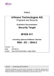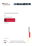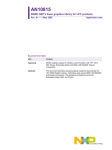
1
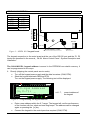
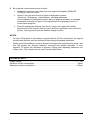
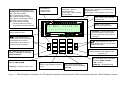
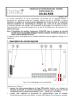
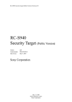
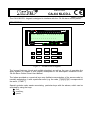
KEYPAD
CA-64 KLCD-L
®
ca64klcd_l_e 10/03
The CA-64 KLCD-L keypad is designed to interface with the CA-64 alarm control panels.
DESCRIPTION
alarm
1
2
ALARM CONTROL PANEL CA-64 LCD
3
4
5
6
7 8
9 10 11 12 13 14 15 16
14 Nov, 13:26:41
.............
17 18 19 20 21 22 23 24 25 26 27 28 29 30 3 1 32
service
1-32 33-64
trouble
armed
1
abc
2
def
3
ghi
4
jkl
5
mno
6
pqrs
7
tuv
8
wxyz
9
¾
0
#
Figure 1. CA-64 KLCD-L keypad.
The keypad features (visual and audible signaling) as well as the way of operating the
alarm system by means of this keypad correspond to the description contained in the
CA-64 Alarm Control Panel User Manual.
The letters provided on numerical keys may facilitate memorization of the access code by
mentally associating it with a particular word (e.g. the code „[7][8][2][7][8]” corresponds to
the word: „START”).
Special symbols make easier associating particular keys with the alarms, which can be
activated by using the keys:
- fire,
- auxiliary,
- panic.
KEYPAD CONNECTION
DESCRIPTION OF TERMINALS
KEYPAD
PANEL
KPD
DTM
CKM
COM
+KPD
DTM
CKM
COM
COM CKM DTM KPD
Z1 – for detector Additional
Z2 – for detector system inputs
RS-232
Z1
Z2
anti-tampering contact
buzzer
Figure 2. – LCD-L V1.2 keypad board.
The keypad connection to the main board and the use of the RS-232 port and the Z1, Z2
inputs are described in the manual „ CA-64 Alarm Control Panel - System Description and
Installation”.
The CA-64 KLCD-L keypad address is saved in the EEPROM non-volatile memory. It
can be programmed in two ways:
1. Directly (skipping the control panel service code):
• Turn off the keypad power supply and the data bus wires (CKM, DTM).
• Short the keypad terminals CKM and DTM.
Turn on the keypad power supply. The following text will be displayed:
alarm
1
2
ALARM CONTROL PANEL CA-64 LCD
3
4
5
6
7 8
9 10 11 12 13 14 15 16
LCD-kpd Address
(n,0-7): _
17 18 19 20 21 22 23 24 25 26 27 28 29 30 3 1 32
service
1-32 33-64
trouble
armed
n=0...7,
current address of
the keypad
Figure 3. – Programming the keypad address
•
•
SATEL
Enter a new address within the 0-7 range. The keypad will confirm performance
of the function with four short and one long beeps. The address can be changed
again on pressing the [¾] key.
Connect the keypad to the control panel as required (CKM, DTM).
-2-
CA-64 KLCD-L
2. By using the control panel service function:
• Activate the panel service mode (from any supported keypad): [SERVICE
CODE][¾], ÆService mode.
• Select in turn the items from the menu of displayed functions:
ÆStructure; ÆEquipment; ÆIdentification; ÆKeypad addresses.
On the displays of manipulators (which have no physical jumpers), a message
will appear as shown in Figure 3 (corresponding to the language version of
control panel program).
• Enter the appropriate address from the 0-7 range; the keypad will confirm
performance of the function with four short and one long beeps; then, press the
[¾] key - the keypad will quit the address change function.
NOTES:
-
For the LCD keypads to be properly supported by the CA-64 control panel, the keypad
identification function must be performed after setting the keypad addresses.
-
Setting the same address in several keypads will trigger the anti-tampering alarm, and
also will display the „Keypad replaced” message and disable operation of such
keypads. To restore the operation of keypads, change their repeating addresses into
unique ones. The changes can be made as described herein.
TECHNICAL DATA
Supply voltage ..........................................................................................................11...14V
Minimum current consumption......................................................................................60mA
Maximum current consumption...................................................................................125mA
SATEL
-3-
CA-64 KLCD-L
[1] do [6] - press and hold for 3 sec.
to get access to viewing functions
[1] - zone status viewing
[2] - keypad tampers viewing
[3] - expander tampers viewing
[4] - partition armed status viewing
[5] - alarm memory viewing
[6] - trouble memory viewing
(see: descriptions of TESTS
and EVENT HISTORY) viewing
SERVICE - blinking when
service mode is active
ALARM
steady light – alarm in
operated partition
blinking light – alarm memory
for the partition
LCD DISPLAY:
- date and time
- partition status
1-32 - zones 1-32 or the first
expander bus
alarm
1
2
ALARM CONTROL PANEL CA-64 LCD
3
4
5
6
7 8
9 10 11 12 13 14 15 16
14 Nov, 13:26:41
[7] - press and hold for 3 sec. to
display a message on currently
detected trouble [*] - press and hold for 3 seconds to
activate FIRE ALARM
CODE+[*] - call user function menu
33-64 - zones 33-64 or
the second expander bus
.............
17 18 19 20 21 22 23 24 25 26 27 28 29 30 3 1 32
service
1-32 33-64
trouble
armed
W X - press and hold for 3
sec. to scroll names of partitions
where alarm has occurred;
press briefly to view names of
partitions shown on display.
ARMED
steady light – all partitions operated by the
keypad are armed
blinking light – some partitions are armed
1
abc
2
def
3
ghi
4
jkl
5
mno
6
pqrs
7
tuv
8
wxyz
9
¾
0
#
TROUBLE – indicates detection of
a technical problem in the system –
to check, press and hold key [7] for
3 seconds
ST - press and hold for 3 sec. to
scroll through names of zones which
triggered an alarm
[9] - press and hold for 3 sec. to
change partition status display mode:
selected / all
[#] - press and hold for 3 seconds
to activate PANIC ALARM
[8] - press and hold for 3 sec. to
switch gong signaling in keypad
on/off
[0] - press and hold for 3
seconds to activate auxiliary
ALARM
0+[#] - arming
CODE+[#] - arming/disarming
Figure 4. - The description of functions of LCD keypad's indicators and buttons for CA-64 control panel with the 1.04.00 firmware version.