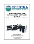
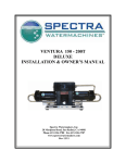
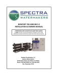
Download NEWPORT 400 Mk II INSTALLATION & OWNER`S MANUAL
Transcript
NEWPORT 400 Mk II INSTALLATION & OWNER’S MANUAL Part 1……....Installation, Operation, Maintenance Part 2………………….. Programming and Controls Spectra Watermakers, Inc. 20 Mariposa Road, San Rafael, CA 94901 Phone 415-526-2780 Fax 415-526-2787 www.spectrawatermakers.com Feb 2012 mpc5000 1 2 Thank you for your purchase of a Spectra Newport system. Properly installed it will provide years of trouble free service. Please pay attention to the installation instructions and the system layout. Like any piece of mechanical equipment the system will require inspection and service from time to time. Do not place the components in inaccessible areas that will prevent proper maintenance. If you are having a dealer install the system for you, review the location of the components to make sure that the installation will meet your approval upon completion. Newport Installation Quick Start Important Details for Installer 1. The system must have a dedicated sea water inlet to guarantee a solid flow of water to the system. The inlet should be as low in the boat as possible and with a forward facing scoop-type thru -hull fitting installed. 2. Both the Newport MkII Feed pump module and the Clark Pump/Membrane module must be installed in a well ventilated compartment where temperatures will not exceed 120F (48C). Many engine compartments exceed this temperature when underway. Warranty will be void if the installation does not meet this requirement. 3. Follow the wire gauge charts in the instructions! Using larger wire than specified is acceptable. 4. If you are separating the Clark Pump/membrane assembly, please review the high pressure tube assembly instructions. Improper assembly will cause failure! 5. Run, test, then “sea trial” the complete system before assuming the system is operational. If the boat is in fresh or dirty water, see “Dry testing the system.” After testing make sure that the flush cycle operates properly. The water going overboard at the end of the flush should not taste salty (<1000ppm) 6. The MPC control must have DC power continuously to achieve the full benefits of the fresh water flush system. The domestic fresh water pressure must be on and the fresh water tank level maintained. Calculate 5 gallons (12L) per flush.. 7. The MPC 5000 control must be de -powered (DC power off) after the system is put in storage. 8. Spectra dealers are responsible for educating the vessel owners on the operation and maintenance of the system. We request that you “walk through” the installation with our customer. 9. Please have the owner fill out the warranty card. The warranty is void if it is not registered. 3 Table of Contents Part 1 Page Number Installation Getting Started..................................................................................................................................................5 Installation Basics.............................................................................................................................................6 Component Placement......................................................................................................................................7 Plumbing ........................................................................................................................................................10 Parker Tube Fitting Assembly Procedure ......................................................................................................14 John Guest Super Speedfit .............................................................................................................................15 Wiring.............................................................................................................................................................16 MPC Tank Switch Wiring and operation .......................................................................................................21 Membrane Pressure Vessel Relocation ..........................................................................................................39 Z Brane Installation ........................................................................................................................................49 Operation New Systems Start Up and Testing................................................................................................................23 Dry Testing.....................................................................................................................................................26 Normal Start Up Using the Auto Run ............................................................................................................27 Automatic Fresh Water Flush Cycle ..............................................................................................................28 Manual Operation...........................................................................................................................................30 Service & Maintenance Long Term Storage Procedures......................................................................................................................31 Winterizing.....................................................................................................................................................33 Maintenance ...................................................................................................................................................34 Membrane Cleaning .......................................................................................................................................35 Salinity Probe Calibration ..............................................................................................................................37 Suggested Spares............................................................................................................................................38 Newport Troubleshooting Procedures............................................................................................................41 Bulletins..........................................................................................................................................................43 Wiring.............................................................................................................................................................53 Clark Pump.....................................................................................................................................................54 Parts List.........................................................................................................................................................59 Part 2 Controls Section 2: Programming & Controls Begins after pg 62 4 Getting Started Unpack the system and inspect it to make sure that it has not been damaged in shipment. Refer to the shipping list for your system to make sure you have received all of the components listed. Do not discard any packaging until you have found and identified all of the parts. The small installation parts are listed on the cellophane bags’ pick list. We will not be held responsible for shortages and or freight damage that are not reported within thirty days of the ship date. Next, study the system layout diagram, component photos and descriptions before beginning your installation. This will assist you in understanding the function of each component. Layout the system. Before starting the installation identify the location where each module and component will be placed. Ensure that there is proper clearance around the components for removal of filters and system service. Also, check to make sure you have adequate tubing and hose before starting, so additional parts may be ordered if necessary. Check to see that the MPC cable is long enough to reach from the display location to the feed pump module. Newport MkII shipping list: Newport Feed Pump Module High Pressure Clark Pump and Reverse Osmosis Membrane Module MkII Fresh Water Flush Module MkII Installation Kit Boost Pump Module Newport Service Kit 1/2” braided hose (10’) 1/2” Black Nylon tube (10’) 5/8” Hose (25’) 3/4” Suction Hose (25’) 3/4” Braided Hose (10’) 5 Installation Basics Thru-hull Not Supplied. Read the directions! Avoid tight hose bends and excessive runs. Use heavy gauge wire. Install feed pump as low as possible. Use a dedicated thru -hull with scoop type strainer. Flow Thru-hulls It is mandatory that a dedicated 3/4” to 1” forward facing scoop type intake thru -hull and seacock be installed. Install the intake for the system close to the middle and as far below the water line as possible. Thru-hulls in the bow area are susceptible to air intake in rough conditions. Sharing a thru -hull with another system is not acceptable and will void the warranty. Sharing a thru -hull can introduce unforeseen problems such as intermittent flow restriction, air bubbles, and contaminates. For racing boats and high speed power boats above 15 knots a retractable snorkel -type thru -hull fitting is preferred to be able to pick up water away from the hull. Do not install the intake close to or downstream of a head discharge. Install as far below the waterline and as close to center line as possible to avoid contamination and air induction. The brine discharge through -hull should be mounted above the waterline, in or just above the boot stripe to minimize water lift. Double clamp all hose connections below the waterline. Pipe Fitting Instruction Plastic to plastic fittings should have 3 to 4 wraps of Teflon tape and will thread almost all the way in. Avoid getting dirt or debris into the piping or hoses during assembly. A small bit of debris can stop the system! Avoid getting tape over the end of fittings that might get into the system. To ensure this does not happen, leave the very first thread uncoated. Avoid restrictions or long runs on the entire inlet side of the plumbing from the thru hull to the main feed pump module. Prevent tight bends and excessive elbows. Any restrictions will hamper system performance. Secure the piping away from moving objects such as engine belts and hatches. Prevent chafe on the tubing as required. Test and inspect all piping and hose clamps after several hours of operation. Wiring Pay attention to wire size or system performance will be impaired. Perform wiring to UL, ABYC, CE or applicable standards. 6 Component Placement Refer to the Plumbing Diagrams Strainer Mount the strainer in an accessible area, close to the intake through hull that can handle water spillage during service. Extra care during assembly must be taken to avoid air leaks from the strainer. Use the supplied “Quick Block” and wire tie for mounting. Fresh Water Flush Module The fresh water flush module may be located in any convenient location near the Feed pump module. It should be mounted with the filter housing vertical and accessible for changing filters. Allow 2” below the filter housing for removal. Do not install over electrical equipment. The unit contains a charcoal filter for the flush water, shut off valve, and flush water pressure regulator. Boost Pump module The boost pump module should be mounted vertically with the service hose connection at the top. The boost pump MUST be installed below the water line to ensure that it will prime. Feed Pump Module Mount the feed pump module on a horizontal or vertical surface that can be up to 3’ (1.0M) above the waterline. It is preferable to mount as low as possible. Locate in an area that allows easy access to the filters, the left hand side, and where water spills during filter changes will not be a problem. Keep future maintenance in mind when choosing a location. The feed pump has overheat protection and will not operate properly at ambient temperatures over 120F (48C). Remove front cover to access mounting holes in the enclosure. 7 Clark Pump/Membrane Module Pressure Relief Valve The membrane maximum temperature specification is 120F. This module must be installed in an area that maintains a temperature below 120F (50C). A cool location is preferable. It may be placed as high in the boat as you desire. Make sure that the area around and under the pump does not have any water sensitive equipment. Water will be spilled during any repairs or if a leak occurs. Be sure you will have access to the pressure relief valve on the Clark pump. The Clark pump/membrane module comes complete with a mounting system. Be sure to use the supplied washers on the rubber feet. Use it as a template for drilling the mount holes. You may mount the Clark Pump in any position, even upside down. Note: If your machine is equipped with the optional Z -brane, see the Z -brane Installation and Operation section of this manual for instructions on installing the Z -brane anodes into the membrane end plugs. This should be done before installing the Clark Pump/ Membrane Module. Membrane Pressure Vessel Mounting The Clark pump and membrane assembly has been pre -assembled at the factory. If it is necessary to disassemble this module and mount the pressure vessel remotely use guidelines in back of the manual. Use only approved tubing for assembly. 8 Remote Control Panel The remote control panel can be mounted anywhere that is dry and convenient. Cut a 4 -9/16” (116 mm) wide by 2-7/8” (68mm) high opening for the panel. Locate in an area that is easily visible and easy to manipulate the buttons. Use only Spectra approved remote cable. The cable is not standard LAN cable or phone cord. Plumbing From the inlet thru hull to the boost pump module and from the boost pump module to pump module inlet use supplied clear 3/4 (19mm) spiral suction rated hose. The outlet of the filter assembly on the main module to the Clark pump assembly is under pressure. Use the supplied braided clear vinyl hose rated to 150 PSI (11 bar). From Clark pump brine discharge connector use supplied 5/8 (15.9mm) clear braided vinyl hose. On the feed pressure side use the supplied Parker 1/2 tube and fittings. Use two grab rings on the 1/2 parker tubing. Refer to the parker assembly instructions. Route all hoses and tubes to prevent kinks and restrictions. Secure piping away from moving objects such as engine belts and hatches. Prevent chafe on tubing as required. Test and inspect all piping and hose clamps after several hours of operation. 9 System Piping schematic From the Clark pump brine discharge connector use the supplied 5/8 (15.9mm) clear braided vinyl hose to the brine overboard fitting. Mount the pressure gauge in the low pressure inlet gauge tee. Use the 1/2 inch nylon tubing between the feed pump module outlet and the Clark Pump inlet Use the 1/2inch braided hose between the Flush module and the Feed Pump Module Flush water from ship’s pressure water system 25 psi (2bar) minimum From the Boost Pump to the 20 micron filter inlet us the 3/4 inch ID braided hose. From the inlet thru hull to the boost pump module use the supplied clear 3/4 (19mm) spiral suction rated hose. 10 Note! When plumbing the Newport Pump Module route the feed water so that the front cover may be opened without removing the hose or tubing. Leave room on this side for attaching tubing and operating the manual button on the diversion valve. Feed water inlet from boost pump. Leave enough extra length in this hose to allow the front cover to be moved aside. Flush water Inlet From Flush Module Feed Water Inlet from Filters Product Water Outlet to Tank Feed Water Outlet to Clark Pump Product Inlet from Membrane 11 Product Water tubing Product water tubing is 1/4 “ (6.3mm) Parker tubing. See the Parker tube fitting assembly diagram on pg 14. Product water goes from the membrane into the pump module manifold where it passes through the flow meter, the salinity sensor and the diversion valve. If the salinity is good the diversion valve energizes and the product goes to the tank from the manifold product outlet. If the diversion valve is not energized the product goes back into the feed water. Connect the product outlet on the membrane housing to the black Product Inlet fitting on the pump module manifold using the supplied 1/4 black nylon tubing. Route the blue product water tube from the blue product water outlet fitting on the feed pump module manifold into the top of the tank. Install a tee in the water tank fill or tap a pipe thread into an inspection port in the top of the tank. Do not feed the water into a manifold or bottom of the tank. Make sure there is no restriction in this plumbing. If the length of product water tubing supplied with the watermaker is insufficient, use a larger size hose. Product water flow restriction will cause reduced and power consumption increased if product flow is restricted. Blue Product tube to Fresh Water Tank Product tube from membrane end cap to feed pump manifold 12 Quick Disconnect Fitting Brine Discharge Route the Brine discharge from the quick disconnect fitting to a location above the waterline using the supplied 5/8” hose. Fresh Water Flush Run a feed line from the domestic cold pressure water system to the 1/2 hose barb on the fresh water flush assembly. This needs to be pressurized when the boat is unattended for the fresh water flush system to function properly. The domestic fresh water pump must be able to deliver 1.5 gallons per minute (6lpm) at 25 PSI. To Flush water Inlet on pump module manifold Fresh water from boat’s pressure water system 13 Parker Tube Fitting Assembly Procedure Spacer Single grab ring for 1/4" & 3/8" tube Use 2 grab rings for 1/2" tube O-ring Body Nut Tubing Step 1: Dissemble fitting components 1/2" max Step 2: Install the Nut first then use the bevelled side of the Spacer to push the Grab Ring onto the tube no more than 1/2". Slip the O-ring over the tube to hold the Spacer in place. If the Grab Ring is pushed too far, trim back the tube so about 1/4" of tube extends past the O-ring. Step 3: Gently fit the tube into the body and loosely thread on the nut. Be careful not to cross-thread the nut 1/2" tube should not bottom out in the fitting to allow full compression of the O-ring Step 4: Hand tighten the nut. DO NOT OVER TIGHTEN! DO NOT USE A WRENCH! The tube should not come out if pulled by hand. If it does, tighten the grab ring tabs. 1/4", 3/8", 1/2" Parker Tube Fitting Assembly 14 John Guest Super Speedfit 15 DC Wiring Identify cables that are connected to the Newport Control System. Newport Mk II Systems have a Power Inlet harness with a terminal block, a 2 conductor boost pump cable, and a 50’ (15M) cable for the MPC -5000 display. A motor speed control sets the run speed and also slows the motor to the flush and service speeds. Do not install it in hot or poorly ventilated locations, and allow for access to the Motor Speed Control. Boost pump cable 50’ (15M) cable with connectors for the MPC5000 control display Power inlet harness with terminal block MPC-5000 controller (Inside Cover) Manual Control Switch Motor Speed Control (Behind the Prefilters, Inside the Chassis) 16 Wiring (continued) Mount the main power terminal block in a junction box or on a bulkhead adjacent to the feed pump module. Make sure that this is a dry location well above bilge level and not subject to water spray. Route the control cable through the boat to the MPC display location. Be careful not to damage the connector or get it wet. Plug this into the back of the control. Connect the red and black Boost Pump wires to the corresponding red and black conductors in the Boost Pump cable (red to red, black to black) using the supplied butt connectors, and heat the connectors to waterproof them. Check the wire size chart to select the proper size power feed to the main power harness. DC power feeds should be uninterruptible to insure proper operation of the auto store feature. Avoid house breaker panels that could be easily tripped. Component Sizing: 12V Use a 30Amp breaker and size the wiring for 25 Amperes. 24V use a 15 Amp breaker and size the wire for 13 Amperes. Provide circuit protection at the source! Inadequate wiring will cause a loss of system performance. DC power should be uninterruptible. Note: If the specified circuit breaker sizes are unavailable use the next higher rating but do not exceed the specification by more then 10%. All wiring to be done to applicable ABYC, Marine UL or CE standards. 17 WIRE SIZE CHART Newport Mk II DC System Wiring Wire Length FT. Meters AWG. SQ MM Mk II 12V 10 3 10 6 15 4.5 8 10 20 6.1 6 16 25 7.6 4 25 30 9.4 4 25 35 10.6 4 25 40 12 2 35 45 14 2 35 50 15 2 35 Meters AWG. SQ MM MkII 24V 10 3 12 4 15 4.5 10 6 20 6.1 8 10 25 7.6 8 10 30 9.4 8 10 35 10.6 6 16 40 12 6 16 45 14 6 16 50 15 4 25 Wire length is measured from source circuit breaker or fuse to control terminal block and back to the source again. 18 MPC Remote Control Display Panels There are currently two types of display options available: Liquid Crystal Diode (LCD) display, which is dark lettering on a backlit background, or Vacuum Florescent Display (VFD), which are bright characters on a dark background. The VFD display brightness can be adjusted using the Programming Function detailed in Part 2 of this manual. The displays must be mounted in a protected location, out of direct sunlight, and away from spray or dripping water. Commands to the system can be entered at any panel. The display panels connect with the supplied 50 foot modular -type cable to the MPC board sockets marked “DISPLAYS.” Do not substitute a different type of cable! Contact the factory if you need longer or additional cables. 19 Connection of Optional Accessories Use of any external devices not approved by the factory may cause permanent damage to the controller and is not covered by the Spectra warranty. Accessory outputs are limited to 2 amps maximum load! Do not connect motors, pumps, etc to accessory outputs. Optional Z-brane System: Detailed instructions are included in the Z -Brane section. Connect to an uninterruptible 12 of 24Volt DC power source. Ultraviolet Sterilizer: Detailed instructions are included with the sterilizer kit. The UV sterilizer lamp module and ballast unit should mount vertically, with the product water inlet at the bottom, outlet at the top. The ballast wires plug into the end of the bulb in the lamp module. The ballast RED wire connects to “STER” terminal on the MPC board, and the ballast BLACK wire connects to the “GND” terminal. If the wires must be extended, use minimum 16AWG wire. External Buzzer(s): In addition to the external buzzer(s) installed at each remote control display panel, a buzzer unit may be installed at the control box. The buzzer RED wire connects to the “BUZZ” terminal on the MPC board, and the buzzer BLACK wire connects to “GND.” Float Switches: Your MPC 5000 can be wired to operate with optional tank float switches for truly automated operation. See the instructions and wiring schematics on the next page for additional details. Order part number EL -SWT-SMLV and EL -SWT-LV for tank low and tank full switches. 20 Tank Switch Installation and Operation: There are two sets of terminals on the MPC -5000 PCB that can be used in four different configurations to automatically start and stop the watermaker or to automatically stop the watermaker when the tank(s) are full without the auto start feature. These terminals are on the green ten pin connector and are labeled “Float Switch 1” and “Float Switch 2.” Float Switch 1 is the tank full switch and Float Switch 2 is the tank empty switch. If the unit is wired for both Autostart and Autostop, it can be put into AutoFill Mode by pushing and holding the Auto Run switch on the MPC -5000 display. In this mode the watermaker will start whenever the water level drops below the tank empty switch, so that it is open (not conducting electricity). When the tank fills up and both the tank full switch and the tank empty switch have remained closed for two minutes, the watermaker will shut down and flush itself. The water maker will start back up when the water level drops below the tank empty switch and it remains open for 2 minutes. This configuration allows for completely automatic operation. If the watermaker does not need to start up within five days it will automatically do a fresh water flush. AutoFill mode can be ended by pushing the stop button or the Autoflush button. If the watermaker is in Autorun mode it can be put into Autofill mode without stopping it by holding down the Autorun button. If the owner prefers to install the automatic shutoff feature without the automatic start up option, only the tank full switch is used. A jumper must be placed between the tank empty terminals (Float switch 2) in place of the tank empty switch, because the watermaker will only shut down if both sets of terminals are closed. To use this mode the watermaker must be started up with the Stop/start button or the Autorun button. DO NOT press and hold the ‘Auto Run’ button, as this will enter the ‘Auto Fill Mode’ and the watermaker will not function properly. The watermaker will then fill the tank and automatically enter the Autoflush mode, fresh water flushing itself every 5 days until another command is given. It is possible to use the autofill feature with 2 tanks. A double throw electrical switch must be installed in a convenient location. If only the single tank full switch is installed in each tank connect the wire From the Float Switch 1 terminal “1” to the common on the switch and run separate wires from the switch to each tank switch. The second wires can both be run to the Float Switch 1 terminal 2. If you are using two switches in each tank you will need a double pole double throw switch. 21 22 New System Start-Up and Testing Use this procedure when starting a new watermaker for the first time and whenever the system contains preservative or cleaning compounds. Avoid running the system if the vessel is in contaminated water, such as in a dirty harbor or canal. The system should be fully run tested before leaving port. It is preferable to sacrifice a filter by running the system in turbid water rather than waiting to get offshore to discover a problem or deficiency in the installation. If the location or weather prevents proper testing refer to the section “Dry Testing.” Warning! Damage may occur if the purge sequence is bypassed and the membrane is pressurized with storage chemical in it. 1. First Check That: Thru-hull valve is open Run Manual/ Run Auto/ Flush Manual Switch in “Run Auto” Position Domestic fresh water pressure system must be on 2. Open pressure relief valve 1/2 turn ! 3. Power up the system to enter “Purge Mode”. Note: The watermaker will not run with the pressure relief valve open unless it is in “Purge Mode”. Instead it will restart twice and alarm “System Stalled”. Alarm will sound Display will read “Open Pressure Relief Now”, Ensure that it is open. Push the Alarm /Display button to silence alarm 23 4. Press Auto Run Button The system will go into a start mode and the feed pump will start shortly after. The system should prime within 60-90 seconds. Check the strainer and the brine discharge for water flow. There should be no bubbles anywhere in the intake hoses and the feed pump should sound smooth after priming. If the feed pump continues to sound rough, find the reason before continuing! Inspect the system for leaks. Note: If you must stop the purge sequence for any reason, the control will default back to the beginning of the purging mode to protect your system. If you wish you can bypass the purge sequence and initiate a normal start. Pressing both “ Auto Run” and “ Stop” simultaneously anytime during the purge sequence will bypass the purge sequence and enable a normal start. In any case do not pressurize the system for the first twenty minutes or more. 5. After the purge sequence. The control will alarm with the message “Close pressure relief valve” - Close the valve and proceed by pressing “ Auto Run.” 6. The system is now running under pressure and making water. The display will read “purging product water.” This mode sends the product water overboard for ten minutes in case there are any residual chemicals in the membrane. Carefully inspect for leaks over the entire system! Shut down the system and repair any leaks you find. 7. The system is now in the operational mode. You may start and run your system as you desire. You will not have to go through the purging mode unless you “de -power” the system. If you do, you can bypass the purging mode by pushing “Stop” and “Auto run” buttons at the same time. It is best to use the Auto-Run and Auto-Store button to start and stop the machine. If you shut down the system from the Stop button, then use the auto store button to do a fresh water flush cycle. 8. Check that the system is operating within its normal parameters. Compare with the chart on the next page 24 Product Flow Newport 400 MkII Will produce 14 -16 GPH (54-60LPH) Salinity Salinity reads in parts per million. System rejects water higher than 750 PPM. Anything below 500 is excellent. Feed Water Pressure Pressure range 90-115 PSI (7-8 BAR) Pressure will be higher in cold water and lower in warm water. Extreme salinity or temperature conditions may result in operating pressures outside of the nominal range Filter Condition PREFILTER warns that filters are getting dirty. Clean filters as soon as convenient. If the graph reaches full scale the machine will automatically slow down to Run Low speed. If it reaches full scale again it will alarm Service Prefilters and shut off the watermaker. Spectra watermakers MPC-5000 programming instructions can be found in section 2 of this manual. DO NOT ALTER THE FACTORY DEFAULT SETTINGS WITHOUT CONSULTING WITH A QUALIFIED TECHNICIAN FIRST! 25 Dry Testing With Artificial Ocean If it is not possible to test run the system with the boat in the water testing may be accomplished with an artificial ocean. Purchase enough salt to make 5 gallons (20 liters) of salt water. Salt water is 32,000ppm or 3% salt by weight. Make sure that the domestic water system is powered up and that there is water in the tank. Confirm that the Charcoal filter is installed in the Fresh water flush module and that the domestic water line had been installed and all valves are open. 1. 2. 3. 4. Open Pressure Relief Valve. Power up the control system. Close the sea cock Press both “ Auto Run” and “ Stop” to bypass the purge sequence. If the motor starts, press Stop immediately and press the Auto run and stop button again until you get a message PURGE MODE BYPASSED. 5. Press the Auto Store button and allow the fresh water flush system to cycle through its timed operation. Perform 5 consecutive flushes to purge all of the storage chemicals out of the system (20 minutes total purging). If you get a SERVICE PREFILTER alarm, the flush water flow is not enough or the feed pump is running to fast. See the instructions for “Flush Cycle Adjustment”. 6. Hook up your service hoses to the Clark Pump and the boost pump module. Route them into a 5 gallon (20 Liter) bucket. Connect a piece of 1/4” product tubing to the product outlet on the feed pump module. 7. Turn the valve on the boost pump module from “ Run” to “Service.” 8. Press auto flush one or two more times to get enough water into the bucket to properly mix your salt water. Close the pressure relief valve and start the system using the “ Auto Run” Button. Slowly begin adding salt. Slowly add 32mg of salt per liter of water in the bucket. Confirm the solution concentration using a hydrometer, if available. If you have no way to measure the salinity, slowly add salt while running the machine until the feed pressure reaches 100psi (7bar). 9. Run and test the system for as long as possible. During the run test carefully inspect for leaks. Check all of the system parameters to make sure the system is operating correctly. Do not allow the water in the bucket to get above 120F (50C). 10. Store the system per the “Storage” instructions. 26 Normal Start Up Using the Auto Run Button If the system contains preservative or cleaning chemicals follow the directions for New System Startup or Membrane damage will occur! Press the Auto Run button once and the system will prime and run for 1 hour. The display reads “AUTO RUN MODE” then “STARTING” with a 30 second priming countdown timer. After the prime, the display reads “AUTO RUN MODE” with a countdown timer. An hour of run time is added, up to 12 hours, with each successive momentary press of the Auto Run button. An hour can be added at any time. The display shows the default readout unless there is an alarm condition. Successive presses of the Alarm/Display button will scroll through the displays starting with “GPH PRODUCT.” Upon auto shut down by the timer or by the optional tank full float switches, the system will automatically fresh water flush and re -flush every 5 days. Pressing the Stop button stops the sequence at any time with no flushes. Normal Operation For optimum performance, Auto run the system as long as possible at one time. Never let the system sit with salt water in it. Never allow continuous air leaks in the intake. Normal Shut Down If the system was started using the Auto Run button, the system will shut off on its own when the selected run time is over and will auto flush every 5 days. Pressing the Stop button at any time will shut off the system with no auto flush function. The optional tank float switches will shut off the system from any mode. If the system was started by the Auto Run button the system will flush and then re -flush every 5 days. If the system was started by the Start/Stop button it will do a 1 time flush. The display will read “TANK/S FULL.” Once one of the tank float switches opens, the alarm and “TANK/S FULL” display will cease on its own. Note that if “TANK/S FULL” is displayed, the system cannot be restarted. 27 Flush Cycle Adjustment Before shipping from the factory the Newport watermaker flush cycle is set to factory default settings. After initial start up, and annually thereafter, the flush cycle should be checked. The water going overboard at the end of the flush cycle should not taste salty (<1000ppm). If the water at the end of the flush is still salty, or to minimize the use of fresh water during the flush cycle, follow these instructions to optimize the cycle. First adjust the flush water pressure regulator. Remove the 1/2 inch vinyl flush water hose where it attaches to the flush water inlet fitting at the feed pump module. Push the Auto store button. Water will begin to flow out of the flush water tube. Using a graduated container, allow the water to flow into the container for exactly thirty seconds, then push the stop button. If more than 3 quarts (3 liters) of water went into the bucket the pressure regulator is set too high, if less the 2.5 quarts went into the bucket the pressure is too low. Adjust the regulator by loosening the lock nut and turning the adjusting screw. Test again until the correct flow is achieved. Reconnect the Flush water tube. Pressure regulator Decrease Speed switch Increase speed switch Next adjust the feed pump flush speed . Mounted under the top of the Feed Pump Module, under the MPC box, is a pump speed controller. On the board are two magnetic switches for adjusting the pump motor rpm. The switches are narrow silver colored bars about 1/2” (1.5cm) long. The Increase Speed switch is labeled S2 and is located in the corner opposite the battery cables. The Decrease Speed switch is labeled S3 and is located just above the battery cables and next to the 6 capacitors. Each time a small magnet is placed near the switch while the pump is running, a signal will be sent to the controller, changing the speed setting, and the pump will speed up or slow down slightly. Adjust the flush speed as follows. Push the Auto Store button. Push the Alarm display button until the display reads PREFILTER GOOD REPLACE. The flush valve will open and water will flow backwards through the filters and strainers. After about 30 seconds the backflush will end and the feed pump will come on, starting the forward flush of the Clark Pump and membrane. After the feed pump starts, close the service valve (handle crossways) or the thru -hull. If the bar graph on the display begins to move toward REPLACE on the gauge the feed pump is trying to pump more water than the Flush module can supply, and should be slowed down. Turn the service valve to Service. Water should flow very slowly out of the garden hose fitting. If flow is more than a trickle, speed up the pump. Optimum flush speed will be the speed at which slightly more water is coming from the flush module than the feed pump is pumping. This setting will ensure that no sea water is drawn in during the flush, but fresh water is not being wasted overboard. Adjust the Pump Off time and Pump On time. The flush begins and ends with the Pump Off Time setting. Pump off time should be set so that the feed pump comes on just as fresh water reaches the sea cock. Pump on time should be adjusted so that the pump runs just long enough for Fresh water to reach the brine overboard fitting, then stops. Pump On and Pump Off times can be adjusted from the laptop computer or the display. See the instructions in Section 2. Flush duration must be set the same as or higher than the total flush time (two pump off times plus one pump on time). 28 Automatic Store Cycle Warning! Proper understanding of the Spectra flush system and the vessel’s fresh water system configuration is mandatory for extended Auto Store cycles. The flush cycles must not be allowed to drain all the fresh water from the vessel or damage to the vessel’s systems may occur. Make sure there is enough water in the fresh water supply system to supply the watermaker for more than the expected time of operation in the “re -flush every 5 days” mode. The Newport 400 MkII units require about 6 gallons (24 liters) every 5 days. Make sure that the pressure water supply is on and will stay on during the flush mode (If this is not possible contact your certified dealer.). Make sure that the pressure relief valve is closed. It should be closed if the system was just used to make water. The auto flush may not operate if the valve is open. The power for the system must remain on during the auto flush mode. Turning off the power will disable the auto store function and damage may occur. Pressing the Auto Store button momentarily will start a flush and then activate the 5 day flush cycle. The flush water solenoid will open and the display will read “FRESH WATER FLUSH” with a countdown timer. After 30 seconds the feed pump will start, after 5 -7 minutes the pump will stop while the flush valve remains open for another 30 seconds. Them the display will read “FLUSH TIMER INTERVAL,” and the countdown timer will reflect the number of hours until the next flush. Pressing and holding the Auto Store button for 3 seconds will engage a 1 time flush. The system flushes as described above but will not re-flush every 5 days. Display will read “FRESH WATER FLUSH” with a countdown timer, then the default display when finished. Pressing the Stop button will cancel the auto store mode and put the watermaker in standby mode. 29 Manual Operation In the event of a component failure resulting in a shut down due to a false alarm, the failed component can be overridden using the Programming Function on the display. High Pressure, Service Prefilter, System Stalled (airlock), and Salinity Probe Failed can be defeated. The other safety shutdowns will still be activated. The pressure sensors and salinity probe can also be calibrated from the display. Complete instructions are found in Part 2 of this manual under “Programming from the Display”. Be absolutely certain that the alarm is in error before defeating the automatic controls. In the event of complete MPC control failure, the system may be operated manually by using the manual run switch on the MPC control box and manually opening the diversion valve. For manual start up, switch on the feed pump by setting the feed pump switch to “RUN MAN”. Shut the unit down if the Clark pump does not cycle, if air is continuously present in the intake line or if the feed pump is excessively noisy. The automatic safety controls are disabled in manual mode. Always discard the product water for the first few minutes of operation. The initial product water from the system may not be potable. Taste the product water before sending to a tank. To get a water sample loosen the 1/4 inch product tube fitting at either the feed pump module or the membrane outlet and collect a sample Check it with a handheld salinity meter or taste it. The diversion valve, an electrically operated three way valve which is normally energized by the MPC controls to send water to the tank, will not open automatically in manual mode. Instead, it must be opened using the mechanical override button on the valve. The valve is located behind an access opening on the left side of the feed pump module. Push the manual override button in and rotate 1/4 turn clockwise to open the valve. MANIFOLD Diversion Valve Manual Override button Diversion valve manual override button 30 Long Term Storage Procedures Watermakers are best run continuously. When not in use, biological growth in the membrane is the leading cause of membrane fouling. A warm environment will cause more growth than a cold environment. The auto fresh water flush system will greatly reduce biological growth but may not stop it completely in certain conditions. The 5 day re -flush feature allows the system to be shut down without any service procedures for extended periods of time but it doesn't replace performing a storage procedure for long periods of non -use. If an optional “Z Brane” water treatment system is installed in the system, the 5 day re -flush will maintain the system as long as unchlorinated pressurized fresh water is provided. System Storage or “Pickling” If the system is to be left unused for more than 2 weeks, perform the following storage procedure. The procedure introduces a chemical compound into the system that prevents biological growth. This procedure requires de-chlorinated water which can be made with the Spectra’s charcoal filter. Charcoal filters last a maximum of 6 months once wetted. Spectra SC-1 a special storage compound used by the US Navy. It is formulated to be compatible with the modern engineering plastics and composites in the Spectra pumps. Do not use any substitute except propylene Glycol, SC-1 Storage Compound has to be mixed at a ratio of 1 Spectra container to 3 gallons (12L) of fresh water to have the proper solution. An average of 2 gallons (8L) of water is in a Newport system. This water has to be figured in to the mixture. A Newport system uses one SC-1 container. Caution! Avoid contact with skin, eyes, or lungs with the storage chemical. 31 Storage Procedure: Step 1: Flush the system twice. Push the “Auto Flush” button on the MPC -5000 display, when the first flush has been completed, press “Stop” to cancel the 5 day interval timer, then press “Auto Flush” again. Step 2: Remove the quick disconnect fitting from the brine discharge outlet of the Clark pump, and replace with the quick disconnect hose from your service kit, and lead the hose to a 5 gallon bucket. Step 3: Push the “Auto Store button: to fill the bucket with 1 gallons of fresh unchlorinated water. When the bucket has reached the desired level Push the “Stop” button Step 4: Connect the hose, using the garden hose barb fitting from your service kit, to the service port of the boost pump module. Lead the hose into the bucket. Turn the service valve on the boost pump module 180°, so the intake is now coming from the bucket. Step 5: Mix the storage chemical compound into the water in the bucket. Step 6: Make sure the pressure relief valve on the Clark pump is Open (unpressurized). Step 7: Set the switch on the pump module to “Service System” to turn on the feed pump. Circulate the storage chemical in the system for approximately 10 minutes. Set the switch to “Run Auto” when finished. Clean Up: Remove the quick disconnect from the Clark pump brine discharge, and replace the original hose that leads to the thru -hull. You may at this point, if you choose to, pump the bucket dry by using the feed pump switch. Stop when the bucket is empty. Turn the service valve 180° back to its original position, and remove the service hose. Turn off the power to the system and the MPC control. LEAVE THE PRESSURE RELIEF VALVE OPEN 32 Storage & Winterizing Warning! Use only potable water antifreeze (Propylene Glycol). Do not use automotive antifreeze (Ethylene Glycol). Propylene Glycol is an effective biocide and antifreeze only at concentrations above 25%. Commercially available products range from 25 to 60 percent. They are usually labeled with a temperature rating. “Minus 50” antifreeze is already diluted to 25%. “Minus 100” is a 60% solution. Purchase the strongest antifreeze available. Use enough to ensure that the system contains at least a 25% solution even after dilution with the residual water inside the watermaker. Step 1: Flush the system twice. Push the “Auto Flush” button on the MPC -5000 display, when the first flush has been completed, press “Stop” to cancel the 5 day interval timer, then press “Auto Flush” again. Step 2: Open pressure relief valve on the Clark pump. Step 3: Pour the propylene glycol into a bucket. Follow the instructions on the container. Step 4: Connect the service intake hose, using the garden hose barb fitting from your service kit, to the service port of the boost pump module. Lead the hose into the bucket. Turn the service valve on the fresh water flush module 180°, so the intake is now coming from the bucket. Step 5: Set the switch on the pump module to “Service System” to turn on the feed pump. Pump as much of the water remaining inside the water maker overboard as possible. Run the feed pump until you see antifreeze begin to appear in the brine overboard hose. Set the switch to “Run Auto” to stop the feed pump. Step 6: Remove the quick disconnect fitting from the brine discharge outlet of the Clark pump, and replace with the quick disconnect hose from your service kit, and lead the hose to the bucket. Step 7: Set the switches to “Service System” and “Flush Auto” to circulate the antifreeze for about ten minutes. Clean Up: Remove the quick disconnect from the Clark pump brine discharge, and replace the original hose that leads to the thru -hull. You may at this point, if you choose to, pump the bucket dry by using the feed pump switch. Stop when the bucket is empty. Turn the service valve 180° back to its original position, and remove the service hose. Turn off the power to the system and the MPC control. LEAVE THE PRESSURE RELIEF VALVE ON THE CLARK PUMP OPEN. 33 Maintenance General Periodically inspect the entire system for leakage and chafe on the tubing and hoses. Repair any leaks you find as soon as practical. Some crystal formation around the Clark pump blocks is normal. Wipe down any salt encrusted areas with a damp cloth. The Seawater Strainer The sea water strainer’s stainless steel element should be inspected, removed, and cleaned as needed. A clogged strainer will cause the MPC control to alarm “Service Prefilters” Be careful to ensure that the thru -hull is closed before disassembly and the seal and element are in place before reassembly. Put the screen up to a light for inspection. When the system is put into storage, remove, rinse, and reassemble dry to impede corrosion. Check frequently during operation. The Prefilters Service the prefilters as soon as possible after the prefilter condition graph begins to rise. If the filter condition graph gets all the way to “Replace” the machine will slow down. When display reaches “Replace” a second time the alarm sounds and the system will shut down to prevent damage. If cleaning and re -using filter elements, clean when the first segment appears on the filter condition bar graph on the LCD display. To service the filters shut off the thru -hull, open the housings, discard the old filters, Clean out the housing bowls, reassemble the housings with new 20 and 5 micron filter elements. The 5 micron filter goes downstream from the 20 micron. Leave dry until next startup. Use only Spectra approved filters or you may void your warranty. The filters may be cleaned up to 3 times with a soft brush and water in a bucket. Occasionally, lightly lube the O-rings with silicone grease. The Charcoal Fresh Water Flush Filter Replace the charcoal filter element at least every 6 months. 34 The Membranes The membranes need to be cleaned only when operating pressures have risen more than 10% or the product quality degrades. The leading cause of fouling in marine use is from biological growth that occurs when the system is left unused without flushing or pickling. Fouling from mineral scaling can happen during operation under certain sea water conditions, and from rust. Monitor the product salinity and feed pressure bar graphs for higher than normal readings for the conditions. Other conditions can cause high pressure such as cold feed water or clogged filters. Low product flow is usually due to low voltage, damaged feed pump or Clark Pump issues. Look for all other causes before cleaning the membrane. Membrane life can be shortened by excessive cleaning. There are two types of cleaners: acid and alkaline. The acid cleaner (SC-3) will remove mineral scaling. The alkaline cleaner (SC-2) is used to remove biological by-products, oil, and dirt particles that get past the prefilters. If membrane performance is reduced and they have not been pickled recently, cleaning with both chemicals is recommended. The acid cleaner should be used first. If the membrane fails to respond to both cleanings, this is an indication of another problem with the system, or that it is time to replace the membrane. Contact Spectra Watermakers before removing a membrane. Membrane Cleaning For normal cleaning, the SC -3 Acid Cleaning Compound is used first, then the SC -2 Alkaline Cleaning Compound. If known bio -fouling is present, the SC-2 may be used first. Use hot water if possible, up to 120° F (45C) is recommended as it greatly enhances the ability of the cleaners to do their jobs. If the history of the system is unknown or has been left “unpickled” for an extended length of time and biological growth is present, it is recommended that the system is cleaned with SC -2, using an alternate source of unchlorinated fresh water before the system is run under pressure. A simple test can be performed to see if biological growth has occurred. Before running the system, remove the prefilters and examine their condition If the housings are full of smelly discolored water, the system was not properly stored. Install clean prefilters if they were bad. Next check the membrane. Attach the brine discharge service hose and lead to a bucket. Open the pressure relief valve one turn, and manually run the system for 30 seconds. Examine the brine water: if it’s discolored and smells bad, perform an SC-2 cleaning with an alternate source of unchlorinated water before running the system pressurized. If the brine is fairly clean, the system can be purged, run normally, and checked for performance. Clean the membranes only if performance is reduced. Heating the water is preferable. One way to do this is to find a camp stove and use a large stainless steel pot to heat the solution in. The cleaning solution throughout the system will heat as it circulates in and out of the pot. An alternative is to heat the one or two gallons of initial water to 120° on the main stove before mixing in the cleaner and circulating it into the system. Periodically stop and reheat the solution. Perform the cleaning procedures while the ship is in acceptable sea water for purging and testing. 35 Note: Procedures are the same for the SC-2 and SC-3 cleaners Warning! The pressure relief valve on the Clark pump must be open for this procedure or membrane damage may result. Maximum pressure 50 psi. A Spectra Cleaning Compound (SC-2 or SC-3) must be mixed with fresh water at a ratio of 1 container of compound to 3 gallons (12L) of unchlorinated water to have the proper solution. An average of two gallons (8L) of water is already present inside a 400 system . This water has to be figured into the mixture. A 400 system will use 1 container of compound. SC -2 and SC-3 are never mixed together. Do not use them for storage pickling solution. Cleaning Procedure: Step 1: Close the seacock. Flush the system twice. Use the “Auto Flush” button on the MPC-5000 display, once the first flush has been completed, press “Stop” to cancel the 5 day interval timer, then press “Auto Flush” again. Step 2: Remove the quick disconnect fitting from the brine discharge outlet of the Clark pump, and replace with a quick disconnect from your service kit, fitted to a hose, and lead the hose to a bucket. Step 3: Press “Auto Flush” again to fill the bucket with 1 gallon (4L) of fresh unchlorinated water. Press “Stop” when the bucket has reached the desired level. Step 4: Connect a hose, using the garden hose barb fitting from your service kit, to the service port of the boost pump module. Lead the hose into the bucket. Turn the service valve on the boost pump module 180°, so the intake is now coming from the bucket. Step 5: Mix the cleaning chemical compound into the water in the bucket. Step 6: Make sure the pressure relief valve on the Clark pump is Open (unpressurized). Step 7: Use the “Run Manual” switch on the MPC control box to turn on the feed pump. Circulate the cleaning chemical in the system for approximately 25 minutes. Allow to soak for several hours or overnight if the solution is cold. Run the pump occasionally to agitate the solution. Set the toggle switch to Auto when finished. Step 8: Turn off the MPC control system (DC) power. Replace the brine overboard hose. Remove the Inlet Service hose and turn the Service valve to the Run position. Step 9: To avoid damaging the membranes, Follow the “New System Startup” Instructions to Purge the chemicals out of the System. 36 Salinity Probe Calibration Salinity is a measurement of dissolved solids in liquid: these solids will conduct electricity to varying degrees. A special probe is used, with two electrical contacts in it, to determine the resistance to the flow of electricity in the liquid. The higher the resistance, the lower the PPM of dissolved solids. In the MkII systems, the salinity probe is located in a port on the bottom of the feed pump module plumbing manifold. This way we can look at the salinity level of the product water before deciding to either reject the water or accept it and divert it into the holding tank. The salinity level in parts-per-million can be seen either through the salinity meter in the software, or on the display. The next step is to decide what medium to use as calibration solution. If a hand -held salinity meter is available, you can simply take a reading of your product water while the unit is running, then calibrate our MPC board to match that reading. As long as you trust the accuracy of your hand -held meter, this is all that is necessary. The microprocessor calculates salinity from the signals sent back to it from the probe. The salinity circuit can be adjusted from the Spectra software by adjusting the “Salinity Calibration” parameter, or from the display in the Salinity Cal window. Increase the calibration parameter to increase the salinity reading. Conductivity calibration solutions are available from Spectra Watermakers if another method of calibration is necessary. These solutions are pre-made potassium chloride solutions with known salinity levels. Calibration consists of inserting our probe into the solution and setting the calibration parameter to the required value. To remove the salinity probe, unplug the telephone style cable from the probe. Use a wrench to unscrew the probe from the manifold. Re -connect the salinity probe cable, and you are ready to calibrate. Place the flat surface of the probe containing the two metal conductivity contacts into the calibration solution being careful not to get the cable or jacks wet. Upon re installation, it is recommended to use Teflon tape on the salinity probe threads before re installing to prevent leaks. We also recommend putting some silicone grease inside the jack, to prevent moisture from causing corrosion inside the jack. *NOTE: If the system was manufactured after April, 2008 the system will use A -34 software or later. This software revision requires a salinity probe that is hardwired at the probe end, and cannot be disconnected. Use caution when removing the probe so the cable is not damaged. 37 Suggested Spares Short term cruising, weekends etc. We suggest a basic cruise kit. Kit consists of 3 ea, 20micron, and 5 micron filters and two SC -1 storage chemicals. Cruising 2 to 6 months at a time. Two basic cruise kits, One each replacement charcoal filter. One replacement feed pump head. Longer than 6 months, Additional filters, offshore cruising kit consisting of Clark pump seals, O-rings, tools and membrane cleaning chemicals. One replacement strainer screen, O -ring for strainer screen, O-rings for filter housing Part Number Spectra Watermakers parts list: SC-1 STORAGE CHEMICAL SC-2 CLEANER SC-3 CLEANER BASIC CRUISE KIT B 5 MIC FILTER 20 MIC FILTER CHARCOAL FILTER 6” STRAINER SCREEN FEED PUMP HEAD 6” STRAINER O-RING FILTER HOUSING O -RING OFF SHORE KIT 40” MEMBRANE KIT-CHEM-SC1 KIT-CHEM-SC2 KIT-CHEM-SC3 KIT-BCK-B FT-FTC-5 FT-FTC-20 FT-FTC-CC FT-STN-6S PL -PMP-140MAG SO-STN-6SS SO-FHS-3PCS10 KIT-OFFSH FT-MB-40 38 Membrane Pressure Vessel Relocation Use ONLY Dayco Imperial Nylo-Seal 88-NSR-1/2 tubing for high pressure connections. Pay attention to the direction and flow path of the tubing before disassembly. Make sure that you reinstall the tubing in the same manner. Rotate the 90 degree high pressure tube fittings on the Clark pump for ideal tube runs. The high pressure fittings are typically pre installed at the factory. These fitting seal with an O -ring and require no Teflon tape or pipe sealing compound. Loosen the backing nut rotate the fitting and reseat the backing nut. Follow the high pressure tube connection instructions on the next page. Connect the tubes to one of the components, secure the tube runs, and then trim and connect to the other component. A 90 degree bend in a tube is better than a 90 degree fitting. A tube, when mounted, should have at least one gentle bend to allow for expansion. Do not connect a tube straight between hard mounted fittings. When connecting the tubes to their components, be sure to hold the fitting body with a wrench during the final tightening. Of special note are the high pressure tube fittings on the membrane housing seal on an O -ring and should be seated all the way in. Hold the fitting with a wrench while installing the tube. The fittings on the Clark pump have an O -ring seal and can be re-oriented by backing out the O -ring Stop nut. Rotate the fitting to align with the tube and tighten the nut just past hand tight. Do Not over tighten! 39 Spectra High Pressure Tube Fitting Assembly Use ONLY Dayco Imperial Nylo -Seal 88-NSR-1/2 tubing for high pressure connections. Carefully fit and measure the tubing before cutting with a sharp razor knife or hose cutter and remove any burrs. Minimum tubing bend radius is 6”. Route tubing away from excessive heat sources and secure from vibration and chafe. Have at least one shallow bend in a tube assembly after it is installed. Refer to figure 1. If a fitting has been dissembled, reassemble as illustrated. The notch on the ferrule must engage the inside of the nut properly for the nut to seat down fully. Once the tube is inserted the ferrule and nut will naturally align. Refer to figure 2. Insert tube fully into the fitting, it should go in 0.9”. Tighten the nut finger tight while moving the tube around to prevent binding. One thread should be showing under the nut. Secure the tube so it won’t back out when tightening. Refer to figure 3. Use 13/16” wrench to hold a straight body fitting or a 3/4” wrench for a 90º body, and a 7/8” wrench for the nut. Hold the body, recheck the tube insertion, then tighten the nut 1 -1/4 turns. Use the index mark on the nut as a guide. The threads should be completely covered by the nut. Make Sure these fittings are tight on initial assembly or they will fail! The correct Torque is specification is 85 foot pounds Index mark Straight thread Straight or 90 deg. 3/8" pipe thread Figure 1. Nut Body Ferrule Nut finger tight with 1 thread showing Cut tube square Black high pressure tubing Figure 2. Tighten 1-2/3 turns (10 flats of the nut) with a7/8" wrench after finger tight. Use index mark as guide No threads showing Figure 3. Insert tube 0.9" until it stops IMPORTANT! Hold fitting body with 13/16" wrench when tightening 40 Spectra Watermakers Newport Troubleshooting Procedures SYMPTOMS PROBABLE CAUSE REMEDY Feed pump runs constantly, will not turn off Manual override switches in “on” position Turn off manual switch on control box Feed pump runs with loud noise - Intake blocked - Air in system - Check thru-hull valve - Check sea strainer for leaks - Check FWF module for leaks - Re-prime system (restart) No lights or display, system does not operate - Remote display not connected - No power to control box - Check display cable connections at back of display and at control box - Check and reset main DC supply breaker - Check for voltage (12 or 24vDC) at control box power input studs - Try manual bypass switches; if pumps run, then control or display is defective Display activates, but pump will not run - loose or broken pump wire connection - speed control overheat - tanks are full - Check wiring at terminal block inside MPC - Improve cooling - Check tanks– system cannot be started if tanks are full. System runs, no product water delivered to water tanks, GPH display shows OK, “Good” LED activated - diversion valve inoperative wiring fault. - disconnected or broken product tubing - diversion valve faulty - Check wiring at diversion valve and inside control box - Check product tubing - Replace valve (contact factory) System runs, no product water delivered to water tanks, GPH shows OK, “reject” LED activated - high salinity of product water, causing system to reject water - salinity probe out of calibration or defective, bad cable - chlorine damage to membranes - pressure relief valve open - Check for low feed pressure, close pressure relief valve - Check for leaks at high pressure hoses - Test product water with handheld tester– if over 750ppm for 1 hour, contact factory Close Valve 41 Spectra Watermakers Newport Troubleshooting Procedures Error Messages SYMPTOMS “System stalled” (“system stalled” may alarm when using the control panel to run system for servicing with the pressure relief valve open– use manual override switch instead) PROBABLE CAUSE - pressure relief valve open intake thru-hull closed air locked system no signal from flow meter REMEDY - Close pressure relief valve - Check thru-hull - Check flow meter wiring at control box - Replace flow meter “High Pressure” - blocked brine discharge - fouled membrane - Check brine discharge - Clean membrane “Voltage Too Low” - battery voltage too low - loose wires or poor connections - Charge batteries - Check charging voltage - Check power connections “Re-starting” - no signal from flow meter at startup. System Air-locked - See remedy above for “system stalled” “Check Fuse” (followed by fuse number) - blown fuse at circuit board - Replace fuse (mini automotive type ATM) - Look for cause “Service Prefilter” - clogged filters - loose or defective pressure sensor wires - Install new filters - Check sensor wiring “Salinity High” - high product water salinity - chlorine damage to membranes - defective salinity probe or cable, cable disconnected - Check for low feed pressure - Check for leaks at high pressure hoses - Remove and clean probe contacts check calibration. - Check cable connections - Clean membrane 42 Operation and Repair Bulletins The following documents are sections of our complete service bulletin set. These are available on our website www.spectrawatermakers.com MEMBRANE CARE Membrane life is affected by a large number of factors and is somewhat unpredictable. A big commercial plant running 24/7 will get 10 to 12 years out of a set of membranes. But they do all kinds of fancy chemical injections and never shut the thing off. Most cruisers are lucky to get five or six years out of one. You hear of the eight or ten year old membrane now and then. The biggest killers of membranes are lack of use, chlorine damage, and improper storage. Don’t let membranes sit around with sea water or stale fresh water in them. Biological growth will occur in the membrane. Here at the factory we frequently get back membranes for inspection that reek of hydrogen sulfide (rotten eggs). This odor is produce by anaerobic bacteria that live in an unused membrane, feeding on whatever animal or vegetable matter is trapped in it from the plankton that gets through the system. Membranes badly fouled in this way can seldom be saved. These bacteria are always present but are inhibited by the oxygen in sea water while the unit is in frequent use, by scheduled fresh water flushes, or by pickling. Keeping the prefilters clean is also important in preventing bio-fouling. If your prefilters are allowed to become a breeding ground for bacteria (get smelly), the contamination will spread throughout the system. When we cut open a failed membrane we also find mildew, another form of bio fouling, probably due to long term storage with no biocide or stale biocide. After many hours of water making mineral deposits will form and must be dissolved away with an acid cleaner. Alkaline cleaners are used for bio-fouling. Cleaning chemicals, especially the alkaline, are not good for the membrane. Every time you clean the membrane it shortens its life. Clean only when necessary, and avoid cleaning as a “diagnostic tool”. Chlorine will destroy a membrane in minutes. It attacks the material that the membrane is made from. Always use product water or water filtered slowly through a charcoal filter for flushing and chemical treatments. Oil simply plugs up the matrix of the membrane and clogs it up. We have brought back oil fouled membranes with Joy soap (See MB -5 Cleaning with Detergent.) For storage we recommend using propylene glycol potable water system antifreeze if available. It can safely be left in the system for one year and will keep things from freezing in cold conditions. It is hard to find in warm climates, and takes up a lot of room on a small boat, so our SC-1 is best for tropical cruising. Given good care a membrane will eventually just start to slowly fade away. The feed pressure may rise and/or the ppm go up. Hardly ever will they just fail overnight. 43 8/13/04 MEMBRANE CLEANING WITH DETERGENT If the membrane has been fouled with oil it may be possible to save it by cleaning it with dish soap such as Joy. Don’t use anything that may contain bleach. You will need quite a lot of chlorine free fresh water. If using shore water run it through a charcoal filter at a rate of not more than 1.5 gallons (6 liters) per minute. Fill a bucket with fresh water and mix in a couple squirts of the detergent. Run the system depressurized with the watermaker drawing water from the bucket and discharging overboard. When about half the water is gone from the bucket stop the unit and let the membrane soak for a few minutes. Restart and pump the remaining solution overboard. Repeat until the discharge appears clean. After most of the oil is cleaned out you can put the brine discharge into the bucket and run the system with the soapy water circulating as you would for the other cleaning chemicals. Rinse the system with a bucket of fresh water or the fresh water flush cycle, then flush for twenty minutes using sea water. Pressurize and test. 5/12/04 44 PURGE MODE BYPASS Whenever the control power (12 or 24 volt DC) has been shut off the system will prompt you through the purge mode when it is turned back on. This is because the only time the MPC-5000 should be turned off is after the system has been pickled. Purge Mode prompts the operator to open the pressure relief and then runs seawater through the system for 20 minutes to clear away the chemicals. Normally, during periods of disuse the MPC -5000 will remain powered up so that it can do the five day flush cycles, and no storage solution will be present. If the control power has been interrupted but the system is not filled with storage solution, Purge Mode can be bypassed by tapping the two left hand buttons at the same time until the display reads PURGE MODE BYPASSED. The buttons must be pushed at exactly the same time. You can’t hold one down and then push the other. From Purge Mode Bypassed you can run the system in any mode. 4/20/04 45 BAD SMELLING PRODUCT WATER The reverse osmosis membrane is permeable by many gases including hydrogen sulfide, the gas that causes rotten eggs to smell the way they do. If there are bad odors in the feed water they will go through the membrane and the product water will be affected. Usually the source of the odor is from the decay of planktonic creatures trapped in the sea strainer and prefilters. These tiny oxygen loving creatures soon suffocate and die inside the prefilter housings when the unit is shut down. Once all the available oxygen is consumed, anaerobic bacteria begin to grow, causing the odor. If a unit being used frequently begins to make smelly water, it will be the prefilters that are the source of the problem. This occurs in a week or two in cold climates, but in less than one night in very warm waters like the Sea of Cortes or Red Sea. These bacteria can spread throughout the watermaker, and begin to grow on the membrane, causing poor water quality and high feed pressures. Filling the system with fresh water after every use greatly slows this process, allowing the automated spectra units to operate with less frequent prefilter changes, but units operated for only an hour or so a day will probably need to have the filters changed due to odor before they are dirty enough to restrict water flow. Prefilters can be cleaned gently a limited number of times. After shutting down the unit remove the used prefilters and install a clean set. Leave the housings full of air until the next use. Given gentle handling, prefilters can be reused up to 3 times. Bad smelling product water is usually caused by bad smelling feed water, but can also be caused by a fouled membrane if the membrane has been left unpickled. If the unit makes smelly but not salty water after a long idle period and the prefilters are new, the smell can be eliminated by running the unit unpressurized for an hour or so to flush the membrane. Odors in the product water can also be eliminated by adding a charcoal filter in the product water line. Spectra offers a product water filter kit p/n KIT -FLT-CC. More on this subject is available on our website at www.spectrawatermakers.com. 8/17/04 46 FRESH WATER FLUSH The purpose of the fresh water flush is to replace the sea water in the watermaker with fresh water whenever the system is not operating. The Auto Flush Mode changes the fresh water every five days if the system has been idle that long. The watermaker will last longer and operate better if it is always kept filled with fresh water between uses. All Newport 400 Mk II Spectra Watermakers are equipped with a fresh water flush module. This module includes a charcoal filter to remove any chlorine in the fresh water that might damage the membrane. The electrically operated solenoid valve opens during the fresh water flush allowing the boats pressurized water system to supply water to the system. The charcoal filter has a maximum flow rate of 1.5 gallons per minute (6lpm) so the feed pump is operated at a reduced speed to avoid exceeding this flow rate. If the ship’s water system is unable to provide flush water at the required flow rate, sea water will be drawn in to make up the difference. This will cause the flush water to be brackish, and ineffective in preserving the watermaker. At initial startup the fresh water flush system should be tested by taking a sample of the brine discharge water just as the flush cycle is ending. This water should not taste salty, and should read less than 1000 ppm on a digital tds meter. The flush cycle can also be tested by closing the sea cock during the flush cycle. If the MPC -5000 display gives a SERVICE PREFILTER alarm this means that the fresh water supply is insufficient. In this case it is very important to either increase the water supply or adjust the feed pump flush speed as shown in the System Startup instructions. Because the pre -filters trap the plankton in the feed water they can be subject to “going anaerobic” or starting to smell like rotten eggs, as the trapped plankton decay. For this reason it is advisable to always put in clean elements if the unit is going to be left on Auto Flush Mode. In daily or regular use the fresh water flush after each shutdown will help prevent this problem, but in excessively warm or fertile waters the pre -filters will need regular attention. 47 CHARCOAL FILTERS The function of the charcoal filter element, p/n FT -FTC-CC, is to remove any chlorine in the fresh water flush water supply. It also removes any particulate matter. The charcoal filter we use removes 99.7% of the chlorine. Beware when buying other charcoal filters. If they don’t specify the percentage of chlorine removed, don’t use them. The cheap ones in most cases will only remove 60 or 70%. Also, there are aftermarket filters which are very close to, but not exactly, the same dimensions that will not seal properly in the housing. The membrane can only handle small amounts of chlorine for short periods without damage. The chlorine will damage the bonding agent in the membrane in a very short time. So if you skimp on the charcoal filter you will toast a $450.00 membrane on the first flush. The other factor is the flow rate that the filter can handle. Because the chlorine is deactivated by a chemical reaction with the charcoal, it must remain in contact with the charcoal for sufficient period of time for the reaction to be complete. The filter we use can handle 1.5 gallons (6 litres) per minute flow, and are good for 5000 gallons (12,000 litres) at 1.5 GPM, or six months, whichever comes first. Regardless of the flow the charcoal loses its effectiveness after six months. 48 Z-BRANE OPERATION MANUAL 49 The Z-brane is a revolutionary product which incorporates the Z -Guard High Voltage Capacitive technology into the membrane pressure vessel. Always active, the Z -Brane creates an environment that is unfriendly to bio -film and bacteria. The Z technology also assists in the prevention of scale formation on the membrane surfaces. The Z -Brane allows the system to be shut down or decommissioned for extended periods of time without chemicals or preservatives. The Z-Brane will not prevent freezing so that in cold climates Propylene Glycol is still required. ANODE INSTALLATION Spectra Watermakers ship the High Pressure Module with the White Z -brane electrodes(s) removed from their socket(s) to prevent shipping damage. Before the High Pressure Module is mounted the anodes should be installed. The socket(s) have been plugged with plastic plugs to keep the membranes clean and moist during shipping and storage. Remove the “C -clips” that secure the plugs, and remove the plugs. Insert an anode into each socket. It doesn’t matter which anode goes in which socket. Insert the anode until the groove is flush with the membrane end plug, so the C -clip will slip into the groove. Install the C -clip screw to secure the clip. C-Clip and retaining screw Shipping Plug C-Clip groove in Anode 50 WIRING The Z-Brane system is integral with the watermaker unit and only requires continuous 12Vor 24V DC power to be operative. Note: There is no reason to open the transformer enclosure. Do not service this unit without disconnecting the power source! There may be high voltage present. It is recommended that the Z -Brane be connected to a discreet continuous power source. The power must be on during the time that the system is operation and during the time the Z -Brane is used for membrane storage. If the power is obtained from the MPC then the MPC must be powered up at all times during storage. This may not be desirable. Fuse the power at the source with a 5 amp fuse or circuit breaker. Red is Positive (+) , Black is Ground (-) Z-Brane Power Harness 51 Operation During normal operation the Red LED should be on . Power needs to be supplied to the Z Brane unit at all times that you wish to have the bio -fouling protection. We recommend that your watermaker be flushed after each use not only to protect the membrane but to prevent corrosion in the feed water system. To achieve full effectiveness thoroughly fresh water flush the watermaker several times before leaving the vessel. The Z-Brane may be de -powered if the system is stored with chemicals or winterized with Glycol. Power on LED High Voltage connector DO NOT DISCONNECT OR SPLICE ANY OF THE HIGH VOLTAGE WIRING! Contact the factory if modifications are required. 52 53 End block B HP-TB-VEB-B1 Valve block HP-TB-VB End block A Composite cylinder and base HP-TB-VEB-A1 Brine out HP-CYL-CCA Pressure relief valve HP-TB-BV Center block HP-CB-CB10 Feed in Stainless steel tube HP-CYL-SST Cylinder ring HP-CYL-R Clark Pump Front View End Cap HP-CYL-EC End block A Valve block End block B Reset button Composite cylinder and base Not on all units HP-TB-RSBT Alternate brine out High pressure in Test port Center block High pressure out Stainless steel tube Cylinder ring Clark Pump Back View End cap 54 5/16"-3 1/4" SS AH Bolts HD-CPS-5/16X3 Relief Valve O-Ring SO-HPP-RV Annular Rings HP-TB-AR Spool Assembly KIT-HP-10VSA Relief Valve HP-TB-BV Annular Ring O-Rings Mount inside Valve Block SO-HPP-AR Valve Block 5/16"- 2 3/4" SS A.H. bolts Reset button and O-ring End block B Piston O-ring SO-HPP-SP, PS20 HD-CPS-5/162.75 Spool piston HP-TB-VSP,VSP20 HP-TB-SR Spacer ring Valve block SO-HPP-VB Valve bore O-ring Valve bore O-ring Spacer ring Spool piston Brine port O-ring End block A SO-HPP-VP Valve spool Pilot port O-rings SO-HPP-PLP Piston O-ring Reversing Valve End Blocks 55 Valve port seals SO-HPP-VP Pilot valve port seals SO-HPP-PLP Piston rod HP-CYL-7/8R Center block cylinder O-rings SO-HPP-ECCB Pilot spool O-rings (4) Mount inside block SO-HPP-PV HP-CB-PVS Pilot spool HP-CB-PPS Pilot valve pin SO-HPP-PS Pin seal O-rings Pilot orifice HP-CB-PO HP-CB-PVPS Pin seals HP-CB-PVCR Clip rings Center block Rod lip seals Mount inside block SO-HPP-PR7, PR10,PR15 Feed in Check valve port O-rings SO-HPP-CVP Check valve assembly Piston to rod O-rings (2) Inside pistons Glass rod models only Center Block Check valve SO-HPP-CVS O-ring Check valve seat HP-CB-CVS Check valve poppet HP-CB-CV Check valve spring HP-CB-SPR Check valve washer HP-CB-CVSW Check valve retainer HP-CB-CVR 56 1/2" SS tube S.S compression fittings Piston with seal HP-CYL-SST HP-CYL-PT PL-MTS-3/8X1/2S Composite cylinder and base HP-CYL-CCA End cap O-ring Cylinder end cap SO-HPP-ECCB HP-CYL-EC Cylinder Ring HP-CYL-R Cylinder Assembly 57 10% CLARK PUMP PARTS LIST PART DESCRIPTION USAGE HP-CB-CB10 CENTER BLOCK 1 HP-CB-INS CENTER BLOCK INSERT 4 HP-TB-VB VALVE BODY 1 HP-TB-BV BLEED VALVE 1 HP-TB-VEB -A1 VALVE END BLOCK A 1 -1/4" 1 HP-TB-VEB -A2 VALVE END BLOCK B 1 -1/4" 1 HP-CB-PVPS PILOT VALVE PIN SEAL 2 HP-CB-PPS PILOT VALVE PIN 2 HP-CB-PVCR PILOT VALVE CLIP RING 2 HP-CB-SPRP CHECK VALVE SPRING PLASTIC (DELRIN) 4 HP-CB-CVSW CHECK VALVE SPRING WASHER 4 HP-CB-PVS PILOT VALVE SPOOL 1 HP-CB-CVS CHECK VALVE SEAT 4 HP-CB-CVR CHECK VALVE RETAINER 4 HP-CB-CV CHECK VALVE 4 HP-TB-AR ANNULAR RING 2 HP-TB-10VSA 10% REV. VALVE SPOOLASSEMBLY 1 HP-TB-VSS REV. VALVE SPOOL SEAL 2 HP-TB-VSP REV. VALVE SPOOL PISTON 2 HP-CYL-EC CYLINDER END CAP 2 HP-TB-EBP END BLOCK PLUG 2 HP-CYL-7/8R PISTON ROD 1 HP-CYL-PT PISTON 2 HP-TB-SR SPACER RING 2 HD-CPS -3/824175 3/8-24X1 3/4 CAP SCREW 8 HD-CPS -5/16X3 5/16-18X3 1/4 CAP SCREW 4 HD-CPS -5/162.75 5/16 X 2 3/4 CAP SCREW 8 HD-WSH-3/8X5/8S 3/8 X 5/8 O.D. SS FLAT WASHER 8 HP-CYL-SST STAINLESS TUBE 2 PL-MTS-3/8X1/2S 3/8"NPT X 1/2"TUBE FITT ST SS. 4 HP-CYL-CC COMPOSIT CYLINDER 2 HP-CYL-CCB COMPOSIT CYLINDER BASE 2 HP-CYL-R CYLINDER END RING 2 PILOT ORIFICE PILOT ORIFICE 1 PL-HP-3/8N GLASS FILLED BLACK NYLON PLUG 3/8'NPT 1 PL-HP-1/4BR 1/4 COUNTER SUNK HEX PLG. 1 PL-MTE-3/4SX1/2 3/4"MPT(ST) X 1/2" TUBE SS FITT. ELL. 2 SO-HPP -PLP PILOT PORTS 8 SO-HPP -PS PIN SEALS 2 SO-HPP -VP VALVE PORTS 6 SO-HPP -CVS CHK. VALVE SEATS 4 SO-HPP -CVP CHK. VALVE PORTS 4 SO-HPP -VB VALVE BORE 2 SO-HPP -ECCB END CAP & CENTER BLOCK 4 SO-HPP -AR ANNULAR RING 4 SO-HPP -PV PILOT VALVE 4 SO-HPP -RV RELIEVE VALVE 1 SO-HPP -CT CONNECTOR O-RING 2 SO-HPP -SP1 SPOOL PISTON O-RING 1" 2 SO-HPP -Q QUAD SEAL 2 SO-HPP -PR10 10%, 20% PISTON ROD 2 58 2/11/2005 NEWPORT-400 MK II FT-STN-6 6" STRAINER (LARGE) PL-BSH-3/4X1/4N 3/4" X 1/4" HEX BUSHING REDUCER NYL PL-VLV-3/4PVC 3/4"NPT X 3/4"FPT 1 -WAY PVC VALVE FT-FHW-3PCS BLUE COLLAR FILTER HOUSING WRENCH PL-MFF-1/4X1/4 1/4"NPT X 1/4"FPT ELBOW FITTING NYL PL-NP-1/4N 1/4" NPT CLOSE NIPPLE PL-PRG-1/4P 1/4" WATER PRESSURE REGULATOR PL-HBS-1/4X1/2 1/4" NPT X 1/2" HOSE BARB ST. NYLON PL-HBE-3/4X1/2 3/4 NPT X 1/2"HOSE BARB ELL. NYLON FT-FTH-10L3PCS 10" LOW PRESS. FILTER HOUSING 3 PCS FM-NPC-SVBM NEWPORT II SERVICE & BOOST MODULE FT-FTC-CC CHARCOAL FILTER PL-VLV-3W3/4 3/4" 3-WAY VALVE FM-MPC-MPCB MPC BOX PL-FHB-3/4X3/4 3/4"FPT X 3/4 HOSE BARB ST. NYLON PL-GHF-GC GARDEN HOSE CAP & PL-GHF-WS GARDEN HOSE WASHER VINLY & PL-GHF-3/4NP 3/4"NPT X 3/4"GHT NIPPLE FM-NPC-MKIIFBK NEWPORT MARK IIA FILTER BRACKET PL-NP-1/2X3/8N 1/2"NPT X 3/8"NPT CLOSE NIPPLE NYL PL-HBE-SFPA SHURFLO PORT ADAPTOR PL-SLN-1/4D12M 1/4" DIVERSION VALVE 12 V (MNF) EL-MPC-RMCD MPC REMOTE CONTROL (LCD) PL-MTE-3/4X5/8P 3/4"NPT X 5/8" TUBE FITT. ELL. PL-MTE-1/2X5/8P 1/2"NPT X 5/8" TUBE ELL FITTING PL-MTE-3/8X1/4JG 3/8"NPT X 1/4"TUBE FITTING ELL PL-MTE-3/4S1/2B 3/4” X 1/2" TUBE FITTING ELL BRONZE FT-FTH-10L3PCS 10" LOW PRESS. FILTER HOUSING 3 PCS PL-MTE-1/4X1/4P 1/4"NPT X 1/4"TUBE FITTING ELL NYL 59 NEWPORT-400 MK II PL-ACC-TK ACCUMULATOR TANK PL-HP-1/2N 1/2" HEX PLUG NYLON PL-TEE-1/2X1/2T 1/2"NPT X 1/2" TUBE BRANCH TEE FM-PVB-PBE PLATE BRACKET END PL-HP-3/8 3/8" HEX PLUG NYLON KIT-HP10 HIGH PRESSURE PUMP 10% FOR N.P.ASSM PL-NLT-1/2HP 1/2" HIGH PRESSURE TUBE (DAYCO) PL-MTE-1/2X1/2P 1/2"NPT X 1/2"TUBE FITTING ELL. NYL PL-MTS-1/2X1/2P 1/2"NPT X 1/2"TUBE FITTING ST. NYL PL-TEE-1/2F1/4G 1/2" FPT X 1/4" FPT GUAGE TEE PL-MTS-1/2X1/2P 1/2"NPT X 1/2"TUBE FITTING ST. NYL FM-PVB-PB PLATE BRACKET KIT-HP-MNTK SPECTRA MOUNT KIT ASSEMBLY PL-HBE-3/4X3/4 3/4" NPT X 3/4" HOSE BARB ELL NYLON FT-FTC-5 5 MICRON FILTER ELEMENT EL-MPC-RMCD MPC REMOTE CONTROL (LCD) FT-FTC-20 20 MICRON FILTER ELEMENT PL-MTS-3/8X1/2B 3/8"NPT X 1/2"TUBE FITTING ST. BRZ. PL-NP-3/4N 3/4" NPT CLOSE NIPPLE NYLON SO-HPP-CT CONNECTOR O -RING PL-FTE-1/8X1/4P 1/8"FPT X 1/4"TUBE FITTING ELL PL-NP-1/8N 1/8"NPT CLOSE NIPPLE NYLON 60 NEWPORT-400 MK II PL-MFF-3/4X3/4 3/4"MPT X 3/4"FPT ELBOW FITT. PL-VLV-3W3/4 3/4" 3-WAY VALVE PL-HBE-3/4X3/4 3/4" NPT X 3/4" HOSE BARB ELL NYLON PL-HS-3/4VN 3/4" VINYL HOSE PL-CLP-10SS #10 HOSE CLAMP EL-FP-BPLDC824 300-1000 BOOSTER PUMP DC 8 -24V FM-NPC-SVBM NEWPORT II SERVICE & BOOST MODULE PL-FHB-3/4X3/4 3/4"FPT X 3/4 HOSE BARB ST. NYLON PL-NP-3/4X5 3/4"NPT X 4.5" NIPPLE POLY PL-SLN-1/4O12VB 1/4"1-WAY SOLENOID VALVE 12V W/O VB EL-MTR-PWMA PULSE SWITCHING MODULE ASSEMBLY EL-SSR-ABS ABSOLUTE PRESSURE SENSOR PL-FTE-3/8X3/8P 3/8"FPT X 3/8"TUBE FITT. ELL. PL-MTS-1/2X5/8P 1/2"NPT X 5/8"TUBE FITTING ST EL-MTR-1/2HP12 1/2HP MOTOR 12V 2000 RPM 48YC TEFC OR EL-MTR-1/2HP24 1/2HP MOTOR 24V,2000 RPM, 48YC TEFC EL-SSR-IFM INLINE FLOW SENSOR PL-MTS-1/2X1/2P 1/2"NPT X 1/2"TUBE FITTING ST. NYL PL-PMP-140MAG MAG. DRIVE VANE PUMP 140 GPH C120 PL-MTE-3/8X1/2P 3/8"NPT X 1/2"TUBE FITTING ELL NYL SUB-NP-MK2-INT NEWPORT MK-II INTAKE MANIFOLD PL-FTE-1/2X5/8P 1/2"FPT X 5/8" TUBE ELL FITTING EL-MPC-SP4 SALINITY PROBE PL-MTE-3/8X3/8P 3/8"NPT X 3/8"TUBE FITTING ELL.NYL PL-NP-1/2X3/8N 1/2"NPT X 3/8"NPT CLOSE NIPPLE NYL 61 NEWPORT-400 MK II EL-SWT-TSBHC TOGGLE SWITCH BOOT SEAL EL-SWT-TG-DPDT TOGGLE SWITCH DP/DT FM-MPC-MPCB MPC BOX EL-MPC-PCBDP MPC-5000 CIRCUIT BOARD PL-HS-3/4VN 3/4" VINYL HOSE PL-HS-3/4SH 3/4" REINFORCE SUCTION HOSE PL-HS-5/8VN 5/8" VINYL HOSE PL-NLT-1/2HP 1/2" HIGH PRESSURE TUBE (DAYCO) PL-HS-1/2VN 1/2" VINYL HOSE 62


