1
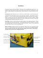
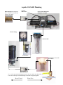
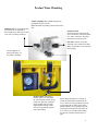
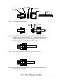
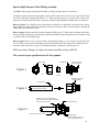
AQUIFER 150/360M OWNER’S MANUAL Spectra Watermakers, Inc. 20 Mariposa Road, San Rafael, CA 94901 Phone 415-526-2780 Fax 415-526-2787 E-mail: [email protected] www.spectrawatermakers.com Rev 06/26/06 f: masterdoc/Aquifer 1 2 Table of Contents Page Number Installation Getting Started................................................................................................................ 5 Installation...................................................................................................................... 6 Salt Side Piping Schematic............................................................................................. 7 Product Piping Schematic............................................................................................... 8 1/4 Inch tube Fitting Instructions..................................................................................... 9 High Pressure Fittings................................................................................................... 10 Wiring Diagram............................................................................................................ 11 Operation New Systems Start Up and Testing ............................................................................... 12 Normal Operation ........................................................................................................ 13 Maintenance................................................................................................................. 17 Service & Maintenance Long Term Storage Procedures ..................................................................................... 14 Winterizing................................................................................................................... 16 Membrane Cleaning...................................................................................................... 18 Suggested Spares .......................................................................................................... 20 Troubleshooting Procedures, Service Bulletins ............................................................. 21 Parts breakdown for AQ-150/360M systems ................................................................. 29 To Order Parts and Supplies: e-mail [email protected]; Contact one of our dealers worldwide; Order online at www.spectrawatermakers.com; or Call customer service at 415-526-2780. Technical Support is available on our website; by e-mail: [email protected]; or by telephone. 3 4 Getting Started Unpack the system and inspect it to make sure that it has not been damaged in shipment. Refer to the shipping list for your system to make sure you have received all of the components listed. Do not discard any packaging until you have found and identified all of the parts. The small installation parts are listed on the kit list. Warning! We will not be held responsible for shortages and or freight damage that are not reported within thirty days of the ship date. Aquifer Shipping List Aquifer Portable Watermaker Seawater strainer Installation Fittings Kit Service Hose kit Hand held Salinity monitor 5/8” Hose (50’) 1/4 product tubing (25’) 5 Installation The Spectra Aquifer 150M and Aquifer 360M come fully assembled and ready for use. It is equipped with quick disconnect fittings for the feed water inlet and brine discharge hoses, and a screw on Parker fitting for the Product outlet. Power terminals are located on the side of the box. Mounting the Case Mount the case in a cool, dry, accessible location. Avoid long feed water suction hose runs and mount the unit as low in the boat as possible. The lid must be able to open fully. The case is splash resistant, but not water tight, and has two louvers for cooling air. Choose a location where any water spilled during filter changes will not be a problem. Install cleats on the mounting surface to prevent the case from sliding around, and strap it down with webbing through the handles on the sides of the case. Feed Water Install a scoop type thru hull fitting as shown in the plumbing diagram. Do not share the thru hull with other equipment. The thru hull fitting should be located low in the boat near midships where air will not be drawn in with the feed water. Install the sea strainer and the male quick disconnect fitting in the supply hose. Brine Overboard Install the female quick disconnect fitting in the brine overboard hose and route it to a thru hull fitting above the water line or to a convenient drain. Always keep the brine hose plug in the brine hose quick disconnect fitting when the hose is disconnected from the case, to prevent water coming into the boat. On-Off Switch Product Flow Meter Feed Pressure Gauge Use these handles for tie down straps Feed Water Inlet Power Inlet Terminals Brine Outlet Cooling air Louvers Product Water Outlet 6 Aquifer 150/360M Plumbing Brine Discharge thru hull place above waterline or tee brine into another visible drain. Pressure Relief Valve Spectra Clark Pump and Membrane assembly. Pressure Gauge 5 micron filter. Accumulator Sea Strainer, Mount with Quick Block Feed Pump Quick Disconnect 1/2” or 3/4 scoop strainer thru hull and seacock for water maker only. Mount low, in a clear flow and away from head discharge. Thru hull is shipyard supplied. 7 Bow of Vessel Water Flow Product Water Plumbing Product sampling valve. Mount using the supplied plastic straps as shown. Note: the handle is pointing in the direction of the flow. Sampling Tap for testing the product water or for service procedures. Put enough tube on this port to reach your service (pickling) container. Product to tank. Route the product water from the valve into the top of the tank. Install a tee in the water fill or tap a pipe thread into an inspection port. DO NOT! feed into a vent line, manifold, or the bottom of the tank. Make sure that there is no restriction in this piping. Use the supplied 1/4” black nylon tubing for the product plumbing Product Outlet Unscrew the product outlet cover and attach the 1/4 inch nylon product tubing using a nut, grab ring, and black plastic washer from one of the supplied Parker fittings. Make sure the O-ring remains in place in the outlet fitting Plastic fittings should have 3-4 wraps of Teflon tape and will thread almost all the way in. Leave the first pipe thread uncoated. Avoid getting dirt or debris in the system during assembly. Secure piping away from moving objects and protect from chafe. Exercise care not to cross thread the fittings. See the tube assembly instructions next page. 8 Spacer O-ring Grab Ring Body Nut Tubing Step 1: Dissemble fitting components 1/2" max Step 2: Install the Nut first then use the bevelled side of the Spacer to push the Grab Ring onto the tube no more than 1/2". Slip the O-ring over the tube to hold the Spacer in place. If the Grab Ring is pushed too far, trim back the tube so about 1/4" of tube extends past the O-ring. Step 3: Gently fit the tube into the body and loosely thread on the nut. Step 4: Push the tube into the body until it bottoms out then hand tighten the nut. DO NOT OVER TIGHTEN! 1/4" Tube Fitting Assembly 9 Spectra High Pressure Tube Fitting Assembly Use ONLY Dayco Imperial Nylo-Seal 88-NSR-1/2 tubing for high pressure connections. Carefully fit and measure the tubing before cutting with a sharp razor knife or hose cutter and remove any burrs. Minimum tubing bend radius is 6”. Route tubing away from excessive heat sources and secure from vibration and chafe. Have at least one shallow bend in thetube assembly after it is installed. Refer to figure 1. If a fitting has been dissembled, reassemble as illustrated. The notch on the ferrule must engage the inside of the nut properly for the nut to seat down fully. Once the tube is inserted the ferrule and nut will naturally align. Refer to figure 2. Insert tube fully into the fitting; it should go in 0.9”.Tighten the nut finger tight while moving the tube around to prevent binding. One thread should be showing under the nut. Secure the tube so it won’t back out when tightening. Refer to figure 3. Use 13/16” wrench to hold a straight body fitting or a 3/4” wrench for a 90º body, and a 7/8” wrench for the nut. Hold the body, recheck the tube insertion, then tighten the nut-1/4 1 turns. Use the index mark on the nut as a guide. The threads should be completely covered by the nut. Make sure these fittings are tight on initial assembly or they will fail! The correct torque specification is 85 foot pounds Index mark Straight thread Straight or 90 deg. 3/8" pipe thread Figure 1. Nut Body Ferrule Nut finger tight with 1 thread showing Cut tube square Black high pressure tubing Figure 2. Tighten 1-2/3 turns (10 flats of the nut) with a7/8" wrench after finger tight. Use index mark as guide No threads showing Figure 3. Insert tube 0.9" until it stops IMPORTANT! Hold fitting body with 13/16" wrench when tightening 10 Aquifer 150 Wiring Route a heavy pair of wires from the main DC electrical panel to the Power Inlet terminals on the outside of the case. Voltage drop will impair performance of the system. Wire length is the sum of the Positive and Negative wires. Wire Size Guide for Aquifer 150 12V Protect with 15 Amp Fuse or Circuit Breaker # 10 Gauge (6mm) to 15 feet (5M) # 8 Gauge (10 mm) to 25 feet (8M) #6 Gauge (16mm) to 35 feet (10.6M) Wire Size Guide for Aquifer 150 24V Protect with 7 Amp Fuse or Circuit Breaker #12 Gauge(4mm) to 10 feet (3M) #10 Gauge (6mm) to 25 feet (8M) #8 Gauge (10mm) to 35 feet (11M) Wire Size Guide for Aquifer 360 12V Protect with 25 Amp Fuse or Breaker #8 Gauge (10mm) up to 15 feet (5M) #6 Gauge (16mm) up to 25 feet (8M) Wire Size Guide for Aquifer 360 24V Protect with 15 Amp Fuse or Breaker #10 Gauge (6mm) up to 15 feet (5M) #8 Gauge (10mm) up to 25 feet (8M) 11 Aquifer M New System Start-Up and Testing Avoid running the Aquifer system if the vessel is in contaminated water, such as in a polluted harbor or canal. The system should be fully run testedbefore going offshore. If the location or weather prevents proper testing contact the factory for information on setting up an artificial ocean Warning! Damage may occur if the purge sequence is bypassed and the membrane is pressurized with storage chemical in it. 1. First check that: Thru-hull inlet valve is open and the brine discharge valve is open. All of your hose connections are tight. The “WARNING” tag and spacer from under the pressure relief valve has been removed. The pressure relief valve is open 1/2 turn. The sampling valve, if installed, is set to the sample position. Remove Tag and Washer! Open 1/2 Turn to Purge Chemicals! 2. Turn on the feed water pump(s). Check that it is primed by inspecting the brine discharge. About 1.5 gpm (6 lpm) of water should be going overboard with a pulsation every few seconds. 3. Run the system without pressure for 20 minutes to purge the storage chemicals. The system should have an open flow pressure on the gauge of about 20 PSI (1.2 bar). 4. Close the pressure relief valve. The pressure should rise to 60-80 PSI (4.2-5.7 bar) for the AQ150 and 95-105 (7 bar) for the AQ360. After several minutes, water should begin to flow out of the sampling tube. If the vessel is located in brackish or fresh water the pressure will be lower. 5. Allow the system to run for 5-10 minutes to purge the product water of storage chemical, and then test the product with your hand held salinity tester. When the product is below 750 PPM it is considered potable and may be diverted to the water container. 12 Aquifer 150/360M Operation Normal operation If the system has been pickled or stored or contains cleaning compounds, use the “New System Startup” procedure. 1. Check to see that the inlet seacock is open. 2. Set up the product tubing so that the product is being discarded and it can be sampled. 3. Start the feed pump and check for flow by inspecting the brine discharge or checking for pressure on your pressure gauge. If there is no flow open the pressure relief valve on the Clark Pump and bleed the air out of the feed pump. 4. Check the product water with your hand held salinity tester. When it is below 750 ppm, you may divert it into your container. 5. Run the system until you have filled your tank or have made enough to meet your requirements for several days. 6. Make about 3 gallons of water into a bucket.This water will be used to flush the salt water out of the watermaker. Use only unchlorinated water for flushing 7. Install the intake service hose and place it in the bucket. Start the feed pump(s) 8. Flush for 2 1/2 minutes or until the pressure drops on the gauge indicating that the membrane is flooded with fresh water. Stop the feed pump. 9. Disconnect and stow service hose. You may now leave the system unattended for up to five days without further attention We recommend operating the system for longer periods and effecting a fresh water flush rather than running the machine every day and not flushing the system. Remember that you need to run the system almost a half an hour to make the flushing water. You may notice that the system output is higher while charging your batteries as the machine is voltage sensitive. 13 Long Term Storage Procedures Watermakers are best run continuously. When not in use, biological growth in the membrane is the leading cause of membrane fouling. A warm environment will cause more growth than a cold environment. System Storage or “Pickling” If the system is to be left unused for more than five days, perform the following storage procedure. The procedure introduces a chemical compound into the system that prevents biological growth. This procedure requires de-chlorinated water. Spectra SC-1 a special storage compound used by the US Navy. It is formulated to be compatible with the modern engineering plastics and composites in the Spectra pumps. Do not use any substitute except propylene glycol. If you wish to use glycol for storage, follow the winterizing instructions. SC-1 Storage Compound has to be mixed at a ratio of 1 container to 3 gallons (12L) of fresh water to have the proper solution for short term storage (under two months use 1/2 of a container) Caution! Avoid contact with skin, eyes, or lungs with the storage chemical. 14 Aquifer 150/360M Storage Procedure 1. Make 4 gallons of product into a bucket. Chlorine free bottled water may also be used. 2. Perform a fresh water flush as described in the Normal Operation section. Leave one gallon of water in the bucket. 3. Connect the brine service hose to the brine outlet on the Aquifer case and place it in the bucket. 4. Add one can of SC-1 storage chemical to the water remaining in the bucket and stir until mostly dissolved. 5. Make sure the pressure relief valve on the Clark Pump is OPEN (unpressurized) by turning it 1/2 turn counterclockwise. 5. Start and run the feed pump(s) to circulate the solution for about ten minutes. 6. Stop the feed pumps. Leave the pressure relief open. Clean Up Remove the service hoses and stow them away in the case. Remove the prefilter from its housing and replace with a clean dry filter element. Close the seacock and drain and clean the strainer and any filters in the system. Reassemble dry. If the unit is to be removed from the boat, disconnect the electrical connections and remove and stow the product tubing. 15 Pickling and Winterizing with Antifreeze The watermaker can be stored for periods up to one year in any climate using this procedure. 1. Make 3 gallons of product into a bucket. Chlorine free bottled water may also be used. 2. Perform a fresh water flush as described in the normal operation section. Run the feed pump(s) until the bucket is empty. 3. Pour 2 gallons of Low Temperature Propylene Glycol Potable Water System Antifreeze into the bucket the bucket. 4. Make sure the pressure relief valve on the Clark Pump is OPEN (unpressurized) by turning it 1/2 turn counterclockwise. 5. Start and run the feed pump(s) until antifreeze begins to come out of the brine overboard hose. 6. Stop the feed pumps. Connect the brine service hose to the brine outlet on the Aquifer case and place it in the bucket. 7. Start the Feed pump(s) and circulate the remaining antifreeze for a few minutes until well mixed. 8. Stop the feed pump and discard any antifreeze remaining in the bucket. 9. Blow out or drain the product tubing, as it will not contain antifreeze. 10. Leave the pressure relief open. Clean Up Remove the service hoses and stow them away in the case. Remove the prefilter from its housing and replace with a clean dry filter element. Close the seacock and drain and clean the strainer and any filters in the system. Reassemble dry. If the unit is to be removed from the boat, disconnect the electrical connections and remove and stow the product tubing. 16 Maintenance General Periodically inspect the entire system for leakage and chafe on the tubing and hoses. Repair any leaks you find as soon as practical. Some crystal formation around the Clark Pump blocks is normal. Wipe down any salt encrusted areas with a damp cloth. If any rust appears at the Stainless Steel fittings, clean them up promptly. Keep the inside of the case dry and salt free to protect the electrical components inside. The Seawater Strainer The sea water strainer’s stainless steel element should be inspected, removed, and cleaned as needed. Be careful to ensure that the thru-hull is closed before disassembly and the gasket is in place before reassembly. When the system is put into storage, remove, rinse, and reassemble dry to impede corrosion. Check frequently during operation. The Prefilter Service the prefilter on a regular basis. The pressure will drop on the remote gauge when the filter becomes dirty. Extremely dirty filters will harm system performance and may cause the feed pump to cycle on the high pressure switch. Do not leave dirty filters in the machine during long idle periods, as biological contamination could result. To service the filter, swing it out of the case,, open the housing, and discard the old filter. Clean out the housing bowl, reassemble the housing with a new 5 micron filter element. Leave dry until next startup. Use only Spectra approved filters or you may void your warranty. The filter may be cleaned several times by soaking it in water in a bucket. Occasionally, lightly lube the filter housing O-ring with silicone grease. The Feed Pump and Clark Pump The feed water pump and the Clark Pump require no routine maintenance except inspection for leaks. Tighten any hose clamps or fittings the show signs of leakage. The high pressure fittings threaded into the Clark Pump have O-ring seals with a straight thread. These should never leak and should never be over tightened. If one of the tube nuts starts to leak, it can be un-threaded, sealed with a bit of silicone grease or silicone seal, and tightened with two wrenches very tightly. 17 The Membranes The membranes need to be cleaned only when feed pressure begins to rise due to fouling or the product quality degrades. The leading cause of fouling is from biological growth that occurs when the system is left unused without flushing or pickling. Fouling from mineral scaling can happen during operation under certain sea water conditions, and from rust. Monitor the product salinity and feed pressure for higher than normal readings for the existing conditions. Other conditions can cause high pressure such as cold feed water or clogged filters. Low product flow is usually due to low voltage, damaged feed pump or Clark Pump. Look for all other causes before cleaning the membrane. Membrane life can be shortened by excessive cleaning. There are two types of cleaners: acid and alkaline. The acid cleaner (SC-3) will remove mineral scaling. The alkaline cleaner (SC -2) is used to remove biological by-products, oil, and dirt particles that get past the prefilters. If membrane performance is reduced and they have not been “pickled” recently, cleaning with both chemicals is recommended. The acid cleaner should be used first. If the membrane fails to respond to both cleanings, this is an indication of another problem with the system, or that it is time to replace the membrane. Contact Spectra Watermakers before removing a membrane. Membrane Cleaning For normal cleaning, the SC-3 Acid Cleaning Compound is used first, then the SC-2 Alkaline Cleaning Compound. If known bio-fouling is present, the SC-2 may be used first. Using hot water if possible, up to 120° (45C) is recommended as it greatly enhances the ability of the cleaners to do their jobs. If the history of the system is unknown or it has been left “unpickled” for an extended length of time and biological growth is present, it is recommended that the system is cleaned with SC -2, using an alternate source of unchlorinated fresh water before the system is run under pressure. A simple test can be performed to see if biological growth has occurred. Before running the system, remove the prefilters and examine their condition. If the housings are full of smelly discolored water, the system was not properly stored. Install clean prefilters if they were bad. Next check the membrane. Attach the brine service hose and lead it to a bucket. Open the pressure relief valve one turn, and manually run the system for 30 seconds. Examine the brine water: if it’s discolored and smells bad, perform an SC-2 cleaning with an alternate source of unchlorinated water before running the system pressurized. If the brine is fairly clean, the system can be purged, run normally, and checked for performance. Clean the membranes only if performance is reduced. Heating the water is preferable. One way to do this is to find a camp stove and use a large stainless steel pot to heat the solution in. The cleaning solution throughout the system will heat as it circulates in and out of the pot. An alternative is to heat the one or two gallons of initial water to 120° on the main stove before mixing in the cleaner and circulating it into the system. Periodically stop and reheat the solution. Perform the cleaning procedures while the ship is in acceptable sea water for purging and testing . 18 Note: Procedures are the same for the SC-2 and SC-3 cleaners Spectra cleaning compound (SC-2 or SC-3) must be mixed with fresh water at a ratio of 1 container of compound to 3 gallons (12L) of unchlorinated water to have the proper solution. About two gallons (8L) of water is already present inside an Aquifer system. This water has to be figured into the mixture. An Aquifer system will use one container of compound. Cleaning Procedure: 1. Make 4 gallons of water into a bucket or obtain 4 gallons of Chlorine free fresh water. 2. Flush the system as shown in the Normal Operation Section. Leave one Gallon of water in the bucket. 3. Connect your inlet service hose and the brine discharge service hose and place them in the bucket. 4. Make sure that the pressure relief valve is OPEN (un-pressurized). 5. Mix the cleaning chemical in the bucket. 6. Start the system and circulate the chemical through the system for 20 minutes. 7. Allow the system to soak for an hour or more, or overnight if the chemicals are cold. 8. Run the Pump(s) for another 20 minutes. 9. Stop the pump, replace the brine overboard hose and start the pump until the bucket is empty. Stop the pump and attach the feed water inlet hose. Restart the pump and run for 20 minutes to flush the chemicals out of the system. (DO NOT CLOSE the pressure relief valve!) 10. The system should now be restarted to make water, fresh water flushed, or stored. . 19 Suggested Spares Short term cruising, weekends etc. We suggest a basic cruise kit A. This kit consists of six 5 micron filters, and 2 SC -1 storage chemicals. Cruising 2 to 6 months at a time. Two basic cruise kits, one replacement feed pump head. Longer than 6 months Additional filters, Offshore Cruising Kit consisting of Clark Pump seals, -Orings, tools and membrane cleaning chemicals. One replacement strainer screen, -Oring for strainer screen, O-rings for filter housing Spectra Watermakers parts list: Part Number SC-1 STORAGE CHEMICAL SC-2 CLEANER SC-3 CLEANER BASIC CRUISE A 5 MIC FILTER CHARCOAL FILTER 5” STRAINER SCREEN FEED PUMP HEAD 5” STRAINER O-RING FILTER HOUSING O -RING OFF SHORE KIT 20” MEMBRANE KIT-CHEM-SC1 KIT-CHEM-SC2 KIT-CHEM-SC3 KIT-BCK-A FT-FTC-5 FT-FTC-CC FT-STN-5S PL-PMP-SFPH SO-STN-5SS SO-FHS-10H KIT-OFFSH FT-MB-20 To Order Parts and Supplies: e-mail [email protected]; Contact one of our dealers worldwide; Order online at www.spectrawatermakers.com; or Call customer service at 415-526-2780. Technical Support is available on our website; by e-mail: [email protected]; or by telephone. 20 Troubleshooting 150/360M Systems Symptom Feed pump runs but no pressure Cause Feed pump air locked Pressure relief valve open Remedy Open pressure relief valve to bleed the air then close to start Close valve Feed pump starts but shuts down on Prefilter excessively clogged high pressure Closed valve or blockage in flow Change filter Low water production High amperage High feed pressure Strainer or prefilter clogged Service prefilter and strainer Low water production, Low pressure Pressure relief valve partially open Worn pump head Close valve Check flow should be 1.4 GPM Replace pump head. Water production normal High feed pressure high amperage Cold seawater temperature Fouled membrane Normal condition Clean membrane Water production normal Lower pressure Lower amperage Warm sea water or brackish water. Normal condition Asymmetrical pressure and flow readings between pump shifts Check valve leaking Failed annular ring Shaft seal leaking Contact dealer or see the Clark Pump repair manual. Check flow path for closed valve or kink in hose To Order Parts and Supplies: e-mail [email protected]; Contact one of our dealers worldwide; Order online at www.spectrawatermakers.com; or Call customer service at 415-526-2780. Technical Support is available on our website; by e-mail: [email protected]; or by telephone. 21 MISC-1 DWYER FLOW METER SERVICE The mechanical flow meter (part no. PL-FMT-XX) used on our manual watermakers can be opened for cleaning if it gets hard to read, or if the little ball in the flow meter is stuck at the bottom. If the ball is stuck, first try giving it a tap to break it loose. The flow meter will come completely apart for cleaning. First, remove the meter from the panel. Next, remove the four small screws that hold the stainless steel bracket in place. Carefully pry off the bracket. On the very top of the meter is a clear plastic slide-off cover that covers a clear plastic allen screw. Use a flat-bladed screwdriver to push the cover off. Holding the meter upright, remove the allen screw with a ¼” allen wrench. Invert the flow meter and catch the ball as it falls out. Now you can get inside and clean things up. You can use tooth paste or plastic window polish to polish the inside using a small bottle brush. Clean the ball and give it a few coats of wax. If the O-rings are damaged or the unit has been leaking, install new O-rings using a little Vaseline or water maker grease to ease assembly. These are standardO-rings and should be available at most larger auto parts or bearing stores. Reassemble in reverse. 5/06/04 To Order Parts and Supplies: e-mail [email protected]; Contact one of our dealers worldwide; Order online at www.spectrawatermakers.com; or Call customer service at 415-526-2780. Technical Support is available on our website; by e-mail: [email protected]; or by telephone. 22 OP-2 BAD SMELLING PRODUCT WATER The reverse osmosis membrane is permeable by many gases including hydrogen sulfide, the gas that causes rotten eggs to smell the way they do. If there are bad odors in the feed water they will go through the membrane and the product water will be affected. Usually the source of the odor is from the decay of planktonic creatures trapped in the sea strainer and prefilters. These tiny oxygen loving creatures soon suffocate and die inside the prefilter housings when the unit is shut down. Once all the available oxygen is consumed, anaerobic bacteria begin to grow, causing the odor. If a unit being used frequently begins to make smelly water, usually the prefilters are the source of the problem. This occurs in a week or two in cold climates, but in less than one night in very warm waters like the Sea of Cortes or the Red Sea. These bacteria can spread throughout the watermaker, and begin to grow on the membrane, causing poor water quality and high feed pressures. Filling the system with fresh water after every use greatly slows this process, allowing the automated Spectra units to operate with less frequent prefilter changes, but units operated for only an hour or so each day will probably need to have the filters changed due to odor before they are dirty enough to restrict water flow. Prefilters can be cleaned. We recommend that you have three sets in service: one in the unit, one set soaking overnight in a bucket of clean fresh or salt water, and one set drying for the next use. After shutting down the unit, remove the used prefilters and install the dry set. Leave the housings full of air until the next use. On nonautomated systems, open the pressure relief when starting if there is a lot of air in the system until the air is cleared out through the brine overboard. The filters will get just as clean when soaked in sea water, but dry much faster if soaked in fresh. Given gentle handling, prefilters can be reused many times. Bad smelling product water is usually caused by bad smelling feed water, but can also be caused by a fouled membrane if the membrane has been left unpickled. If the unit makes smelly but not salty water after a long idle period and the prefilters are new, the smell can be eliminated by running the unit unpressurized for an hour or so to flush the membrane. Odors in the product water can also be eliminated by adding a charcoal filter in the product water line. Spectra offers a product water filter kit (part no. KIT-FLT-CC). More on this subject is available on our website at www.spectrawatermakers.com. 8/17/04 To Order Parts and Supplies: e-mail [email protected]; Contact one of our dealers worldwide; Order online at www.spectrawatermakers.com; or Call customer service at 415-526-2780. Technical Support is available on our website; by e-mail: [email protected]; or by telephone. 23 OP-3 CHEMICALS 101 Spectra Systems use four types of chemicals: SC-1, SC-2, SC-3, and propylene glycol antifreeze. NOTE: Never use any chemicals with the system pressurized! Always open the pressure relief valve 1/2 turn. Always purge a system containing chemicals for at least 20 minutes unpressurized before pressurizing and making water. The SC-1 is for storage only. It is no longer used as a cleaning chemical. To prepare the system for storage, first do a fresh water flush until the brine dischargeis below 1000 ppm or does not taste salty. Mix one jar of SC-1 with 1 to 2 gallons of product or dechlorinated fresh water in a bucket and circulate UNPRESSURIZED with the fresh water in the system for 10 minutes, then discard. The system should be repickled every six months in warm conditions, and every eight months in cooler conditions. The Spectra systems should be stored with propylene glycol if freezing could occur. This is the food grade antifreeze used to winterize RVs, boats and cabins. This works very well for storing in warm climates and is good for one year. See “OP-1 Winterizing or Pickling With Antifreeze” for instructions on this procedure. NOTE: Do not use metasodium-bisulfate, the standard chemical used to store most watermakers. This chemical will damage the Clark Pump and void the warranty. CLEANERS: Cleaning can be detrimental to the membrane and shorten its life. Avoid unnecessary cleaning. Avoid cleaning as a diagnostic tool. SC-2 is an alkaline cleaner used to remove light oil, grime and biological growth. It is most effective if heated to 120 oF. On a boat, this is not easy to do. If not heated, circulate for 2 hours and let set for several hours and recirculate for one hour and discard. In most cases the water quality will increase in PPM after an SC-2 cleaning. After a few hours it should recover to near the PPM it produced before the cleaning. SC-3 is an acid cleaner used to remove mineral and scale deposits. This is used in the same way as the SC-2. In most cases this is used first, and if no results are achieved, proceed with the SC2. SC-3 will in most cases lower the product PPM and over all pressures. Scaling is a slow process that may take several months or years. SC-3 is less harmful to the membrane and will almost always improve the performance of an older membrane. 7/19/04 To Order Parts and Supplies: e-mail [email protected]; Contact one of our dealers worldwide; Order online at www.spectrawatermakers.com; or Call customer service at 415-526-2780. Technical Support is available on our website; by e-mail: [email protected]; or by telephone. 24 PF-3 PREFILTERS– ShurFlo Up to four different filters are used on all Spectra Systems using ShurFlo feed pumps to ensure that no damaging foreign materials enter the system. There are 2 or 3 filters in the system to clean the feed water of abrasive materials while the system is in operation, and an additional filter to prevent the entrance of chlorine during fresh water flushing. During normal operation, the feed water is filtered in two stages. First it enters a fine mesh metal sea strainer, which protects the feed pump from damage due to foreign materials and larger sea creatures. After passing through the pump, the feed water enters the filter housings containing 20 and 5 micron elements. These filters remove very fine particles which could damage the Clark Pump and shorten membrane life. Some units have only the 5 micron filter. Cleaning schedules will vary widely depending on how and where the system is used. If large amounts of feed water are run through the system over a relatively short period of time in biologically fertile near-shore waters, the prefilters will plug up, the pressure drop across the filters will increase, production and quality will drop, and the system will sense plugged filters and give a “Service Prefilters” or “Check Strainer” alarm, if so equipped. Plugged filters can be cleaned several times by soaking in a bucket, towing behind the boat at moderate speeds, or hosing them off. When operated for only an hour or two a day in inland or near-shore waters, the trapped plankton will begin to decay in the filters long before the elements plug up, and the bacteria involved in the decay will cause a “rotten egg” smell in the product water. This decay will set in overnight in tropical waters, or after a week or two in high latitudes. If handled gently and changed regularly before they get too smelly, filters in this service can last through dozens of cleanings. In crystal clear blue water conditions, the filters may need to be cleaned much less frequently. The charcoal filter used in the fresh water flush system will not plug up unless you have some incredibly dirty domestic water in your boat. About six months after installation, the charcoal filter element will lose its effectiveness at removing any membrane -damaging chlorine which may be present in domestic water. Charcoal filter elements must be replaced every six months if there is ANY chance that chorine could be introduced into the flush water. To ensure that filter elements fit properly and remove chlorine effectively, they should be purchased at factory authorized dealers. Our element part number is FT-FTC-XX. The last two digits indicate the micron rating, e.g. FT-FTC-05 is for a 5 micron element. Charcoal elements are FT-FTC-CC. 06/03/04 To Order Parts and Supplies: e-mail [email protected]; Contact one of our dealers worldwide; Order online at www.spectrawatermakers.com; or Call customer service at 415-526-2780. Technical Support is available on our website; by e-mail: [email protected]; or by telephone. 25 MISC-3 ACCUMULATOR PRESSURE All Spectra Watermakers except the Newport 700 and 1000 series are supplied with a pressure accumulator tank, (part no. PL-ACC-TK) to be installed in the feed water line between the prefilters and the Clark Pump. In addition, the Catalina 300 and Newport 400 series also have an accumulator mounted inside the fresh water flush module. The purpose of the feed line accumulator is to reduce the spikes in the feed pressure caused by the cycling of the Clark Pump. If the accumulator is not properly charged it can lead to problems with the ShurFlo pump pressure cutout switches. The accumulators have an air valve on top similar to those found on car tires. This allows the internal air bladder of the accumulator to be pre-charged. The accumulator should be pumped up to about 65 psi (4.5 bar) for best results. Add air using a tire pump or air compressor. You can experiment with the exact pressure that will give the best pulsation dampening on your installation. The purpose of the fresh water flush accumulator is to allow a steady flow of 1.5 gallons per minute of flush water through the charcoal filter. Because the feed pump on the 300 and 400 hundred series exceeds this maximum allowed flow rate, the controller turns it on and off, to reduce the overall flow rate. The accumulator gives the water flowing through the charcoal filter somewhere to go while the feed pump is cycled off. The flush water accumulator should be preloaded to 5 psi (.35 bar). 9/27/04 To Order Parts and Supplies: e-mail [email protected]; Contact one of our dealers worldwide; Order online at www.spectrawatermakers.com; or Call customer service at 415-526-2780. Technical Support is available on our website; by e-mail: [email protected]; or by telephone. 26 SF-1 SHURFLO PUMP WON’T RUN If the pump has power to it (the fan runs), but the pump itself won’t run, the first thing to check is the pressure switch. The pressure switch (part no. EL-FP-PS) is located on the wet end of the pump and has two red wires plugged into it. Jump the two red wires together and see if the pump runs. You can safely run the system with the pressure switch jumped, just keep an eye on the pressure gauge and don’t let system pressure exceed 110 psi. Replace the switch when a spare is available. If the pump will not run with the pressure switch jumped, then it is most likely a problem with the brushes or the overheat protection switch inside the motor. The motor will come completely apart by removing the two screws on the end of the motor. Remove the rear cover and paper insulator. Pull out the plastic brush holder. The thermal switch is located on one of the brush leads. With an ohmmeter, check for continuity through the switch. If it is open, you can make temporary repairs by wiring around it, being careful that your new wiring doesn’t chafe on the moving parts, nor resist the springs that push the brushes on to the commutator. If any corrosion is apparent, the brushes may be sticking. Once apart, clean all the carbon dust from all the parts. Clean the commutator with light sand paper. Make sure to clean the small grooves on the commutator with a small sharp tool to remove the carbon in between the segments. Adjust the springs on the brush holders so the brushes slide smoothly in and out.If the bearings are rough and binding, remove the rubber dust cover and clean the best you can,grease them, and work it free by hand. Don't service the bearing unless absolutely necessary. Reassemble in reverse order. You can hold the carbon brushes back with papers clips inserted through the slots in the brush holder so they don't hang up on the bearing during assembly. Make sure the corrugated bearing shim doesn't push out, if it does, push it back into place. This will at least keep you going until the motor can be replaced if necessary. 6/03/04 To Order Parts and Supplies: e-mail [email protected]; Contact one of our dealers worldwide; Order online at www.spectrawatermakers.com; or Call customer service at 415-526-2780. Technical Support is available on our website; by e-mail: [email protected]; or by telephone. 27 SF-2 ADJUST SHURFLO PRESSURE SWITCH The ShurFlo feed pumps are equipped with a high pressure cut out switch (part no. EL-FP-PS). This is the small black unit on the end of the wetted end of the pump head (part no. PL -PMPSFPH) where the two red wires connect. If the pressure switch is not properly adjusted, the pump may cut out each time the Clark Pump cycles and the feed pressure spikes. When this happens, the production will drop and an unusual noise will be heard when operating on two pumps, but the system will function normally during single pump operation on either pump. The points in the switch will fail fairly quickly if set too low because of the constant arcing from cutting out each time the Clark Pump shifts. For all systems except the Gulfstream, the feed pumppressure switches should be set to shut off at 125 psi (8.5 bar) as follows: On the very center of the switch is a small 5/64” allen screw. Run the system on pump one and close the brine discharge valve 1(/2 way 90 deg) to block the flow. Watch the pressure gauge and adjust the pressure switch to shut off at 125 psi. Repeat for pump two. Turn the allen screw clockwise to increase the cut off set point. Gulfstream models could experience seal failures in the manifold if pressurized too high. For this reason the pump should be removed from the system and the switch adjusted using a separate pressure gauge. If replacing a feed pump or pump head for a Gulfstream model, arrange to preset the switch before installation. 8/05/04 To Order Parts and Supplies: e-mail [email protected]; Contact one of our dealers worldwide; Order online at www.spectrawatermakers.com; or Call customer service at 415-526-2780. Technical Support is available on our website; by e-mail: [email protected]; or by telephone. 28 Part Numbers Front View 1/2” High Pressure Tube PL-NLT-1/2HP CLARK PUMP KIT-HP-10R STAINLESS STEEL HIGH PRESSURE ELBOW PL-MTE-3/4SX1/2 PRODUCT OUTLET FITTING PL-FTE-1/8X1/4P Plate Bracket End Cap FM-PVB-PBE NIPPLE PL-NP-1/8N STAINLESS STEEL HIGH PRESSURE STRAIGHT FITTING PL-MTS-3/8X1/2S Rear View 3/4”-16 Straight Thread O-RING SO-FT-STF Plate Bracket FM-PVB-PB Pressure Vessel End Cap FT-PV-EP Rubber Mount HD-RBP-RM Plastic Spacer HD-SPN-MKINS 1/2” Stainless Ferrule PL-HWR-1/2FR Pressure Vessel End Ring FT-PV-ER Connector O-RING SO-HPP-CT Stainless Fitting Hex Nut PL-HWR-1/2HN To Order Parts and Supplies: e-mail [email protected]; Contact one of our dealers worldwide; Order online at www.spectrawatermakers.com; or Call customer service at 415-526-2780. Technical Support is available on our website; by e-mail: [email protected]; or by telephone. 29 Feed Pump 12Volt, EL-FP-12V Pump Head Assembly W/Press. Switch PL-PMP-SFPH Feed Pump 24Volt EL-FP-24V 3/8”NPT X 5/8” Hose Barb El. PL-HBE-3/8X5/8 Feed Pump Pressure Switch EL-FP-PS Fig 2 Fig 3 To Order Parts and Supplies: e-mail [email protected]; Contact one of our dealers worldwide; Order online at www.spectrawatermakers.com; or Call customer service at 415-526-2780. Technical Support is available on our website; by e-mail: [email protected]; or by telephone. 30 PART NUMBERS PRODUCT WATER SAMPLING VALVE PL-VLV-3W1/4 1/4 TUBE X 1/4 MPT STRAIGHT FITTING PL-MTS-1/4X1/4P 1/4 TUBE X 1/4 MPT EL PL- MTE-1/4X1/4P ACCUMULATOR PL-ACC-TK 1/8MPT X 1/4 TUBE EL PL-MTE-1/8X1/4P 1/2MPT X 5/8 HOSE BARB PL-HBS-1/2X5/8 1/2” TEE PL-TEE-1/2FN 1/2” NIPPLE PL-NP-1/2N PRODUCT FLOW METER PL-FMT-10 1/4MPT X 1/4 TUBE STRAIGHT FITTING PL-MTE-1/4X1/4 1/2 X 1/4 BUSHING PL-BSH-1/2X1/4N PRESSURE GUAGE PL-PSG-2.5L 1/4FPT X 1/4 TUBE EL PL-FTE-1/4X1/4P PREFILTER HOUSING FT-FTH-10L 5 MICRON FILTER CARTRIDGE FT-FTC-5 SEA STRAINER FT-STN-5 STRAINER SCREEN FT-STM-5S To Order Parts and Supplies: e-mail [email protected]; Contact one of our dealers worldwide; Order online at www.spectrawatermakers.com; or Call customer service at 415-526-2780. Technical Support is available on our website; by e-mail: [email protected]; or by telephone. 31 End block B HP-TB-VEB-B1 Valve block HP-TB-VB End block A Composite cylinder and base HP-TB-VEB-A1 Brine out HP-CYL-CCA Pressure relief valve HP-TB-BV Center block HP-CB-CB10 Feed in Stainless steel tube HP-CYL-SST Cylinder ring HP-CYL-R Front View Clark Pump End Cap HP-CYL-EC End block A Valve block End block B Reset button Composite cylinder and base Not on all unitsHP-TB-RSBT Alternate brine out High pressure in Test port Center block High pressure out Stainless steel tube Cylinder ring Clark Pump Back View End cap To Order Parts and Supplies: e-mail [email protected]; Contact one of our dealers worldwide; Order online at www.spectrawatermakers.com; or Call customer service at 415-526-2780. Technical Support is available on our website; by e-mail: [email protected]; or by telephone. 32 5/16"-3 1/4" SS AH Bolts HD-CPS-5/16X3 Relief Valve O-Ring SO-HPP-RV Annular Rings HP-TB-AR Spool Assembly KIT-HP-10VSA Relief Valve HP-TB-BV Annular Ring O-Rings Mount inside Valve Block SO-HPP-AR Valve Block 5/16"- 2 3/4" SS A.H. bolts Reset button and O-ring End block B Piston O-ring SO-HPP-SP, PS20 HD-CPS-5/162.75 Spool piston HP-TB-VSP,VSP20 HP-TB-SR Spacer ring Valve block Valve bore O-ring SO-HPP-VB Valve bore O-ring Spacer ring Spool piston Brine port O-ring End block A SO-HPP-VP Valve spool Pilot port O-rings SO-HPP-PLP Piston O-ring Reversing Valve EndoneBlocks To Order Parts and Supplies: e-mail [email protected]; Contact of our dealers worldwide; Order online at www.spectrawatermakers.com; or Call customer service at 415-526-2780. Technical Support is available on our website; by e-mail: [email protected]; or by telephone. 33 Valve port seals SO-HPP-VP Pilot valve port seals SO-HPP-PLP Piston rod HP-CYL-7/8R Center block cylinder O-rings SO-HPP-ECCB Pilot spool O-rings (4) Mount inside block SO-HPP-PV HP-CB-PVS Pilot spool HP-CB-PPS Pilot valve pin SO-HPP-PS Pin seal O-rings Pilot orifice HP-CB-PO HP-CB-PVPS Pin seals HP-CB-PVCR Clip rings Center block Rod lip seals Mount inside block SO-HPP-PR7, PR10,PR15 Feed in Check valve port O-rings SO-HPP-CVP Check valve assembly Piston to rod O-rings (2) Inside pistons Glass rod models only Center Block Check valve SO-HPP-CVS O-ring Check valve seat HP-CB-CVS Check valve poppet HP-CB-CV Check valve spring HP-CB-SPR Check valve washer HP-CB-CVSW Check valve retainer HP-CB-CVR To Order Parts and Supplies: e-mail [email protected]; Contact one of our dealers worldwide; Order online at www.spectrawatermakers.com; or Call customer service at 415-526-2780. Technical Support is available on our website; by e-mail: [email protected]; or by telephone. 34 1/2" SS tube S.S compression fittings Piston with seal HP-CYL-SST HP-CYL-PT PL-MTS-3/8X1/2S Composite cylinder and base HP-CYL-CCA End cap O-ring Cylinder end cap SO-HPP-ECCB HP-CYL-EC Cylinder Ring HP-CYL-R Cylinder Assembly To Order Parts and Supplies: e-mail [email protected]; Contact one of our dealers worldwide; Order online at www.spectrawatermakers.com; or Call customer service at 415-526-2780. Technical Support is available on our website; by e-mail: [email protected]; or by telephone. 35