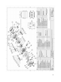
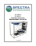
1
LB 10,000 F With SP -20 Pearson Pump Technology Operating Instructions Spectra Watermakers, Inc. 20 Mariposa Road, San Rafael, CA 94901 Phone 415-526-2780 Fax 415-526-2787 E-mail: [email protected] www.spectrawatermakers.com Dec 2011 2 Table of Contents Installation Instructions Getting Started Introduction Installation and Setup Plumbing and Controls Plumbing Schematic Electrical Connections Page 5 6 8 9 11 12 Operation Initial Start-up Normal Operation Fresh Water Flushing 13 15 17 Care and Maintenance Maintenance Oil Changes Long Term Storage Winterizing Membranes Clean-in-Place Procedures Troubleshooting 18 19 20 21 22 23 24 Reference Wiring Diagram Specifications Pump Breakdown 26 27 28 3 4 Getting Started Thank you for trusting Spectra Watermakers for your water purification needs. The Spectra LB-10,000 comes equipped with the revolutionary Spectra Pearson Pump. This is a unique high pressure pump with integrated energy recovery that allows users to purify up to 420 gallons of seawater per hour on as little as 3 KiloWatts. If properly installed and cared for, your system will provide you with years of high quality, potable, fresh water. Please take a moment to review this manual before operating the machine. Parts List: 1 1 1 1 2 1 1 Spectra Pearson Pump High Pressure Assembly Electrical Control Box Pressure Gauge Panel Flow Gauge Panel 5 Micron Prefilter Housings Service Kit Installation/Users Manual 1 Product Water Manifold The product water manifold is removed from the membrane array during shipment to protect against damage. In must be installed prior to use. See installation and setup instructions for more detail. **Please inspect the contents of your shipment to ensure that all parts have been included. Any missing or damaged parts not reported to the factory with 1 business day of taking delivery will be considered lost and replacements will be supplied at list price. 5 Introduction to your System The Spectra LB -10,000 watermaker is designed to be installed on level ground in a building or pump house. Feed water must be supplied from a well or cistern capable of supplying: Up to 20 gpm (76lpm) at 20psi (1.5 Bar) maximum pressure. Feed water should be pre -filtered to a minimum 50 microns before going through the Spectra supplied 5 micron filters. The machine separates the feed stream into two streams, a product stream and a brine stream. The brine contains the dissolved solids removed from the product water. Brine flow may be as high as 13 gpm (50L/min), depending on the running speed of the Spectra -Pearson Pump. The brine may be returned to the ground via an injection well, discarded into a storm drain, or disposed of in another manner as required by local authorities. Consult your dealer, the factory, or local government agency for more information about the best brine system for your application. LB 10,000 Frame Constructed of stainless steel, the overall frame contains all the equipment necessary to operate the desalinator. The frame must be mounted upright on level ground. Positively fix the frame to a sub -floor or concrete base to keep the unit from tipping during service, maintenance, or any inclement weather or seismic activity. 20” Prefilter Housing Contains the 5 micron feed water prefilter and housing. They are preinstalled inside the frame. The filter housing lids have a black, spring loaded “purge” button to allow air to be bled off during startup. Do not leave any electrical device below the filters during operation or service, as some water will be spilled when changing the 5 micron filter. Spectra Pearson Pump High Pressure Assembly This includes the Spectra Pearson Pump, Membranes, Motor and Belt drive system. It is coupled to 3ea 8” x 40” seawater membranes. All high pressure fittings between the membranes and the pump come pre assembled and connected. The fittings are 1” JIC 37 deg. flare fittings. This equipment is factory installed and should not be removed except by a qualified agent. Consult your nearest distributor if you need to order longer lengths of high pressure hose for special installations. 6 Control Panel The LB -10,000 control panel has a series of analog gauges and valves mounted for easy reference to system operating parameters. There are two flow meters, one to measure the inlet flow from the well pump, the other to measure the product water volume. There are also 2 pressure gauges mounted next to the control box. One pressure gauge measures membrane pressure, the other measures the inlet pressure from the supply pump. There are factory set pressure switches installed to ensure that the membranes do not over-pressurize and that there is a minimum supply pressure from the boost pump. Pressure Gauges Plumbing Manifold and Flow Meter connections Control Box The FRP watertight box contains the “brains” of the LB -10,000. This box controls the run and flush speeds, activates the fresh water flush mode, and houses all of the necessary electronics to run the system. This module should be kept away from any water source or where it could get sprayed or wet. Do not operate the machine with the control box open. Should the need arise to open the electrical box after installation, use caution as there is potentially live AC wires inside (AC systems only). 7 Installation and Setup Mounting: Your Spectra LB 10,000 F system is designed to be mounted on level ground and properly fixed in place. If the system is on a slope, then it may not function properly and damage could occur. Use caution that the system will not be knocked over accidentally, and that precautions are taken against any motion due to inclement weather or seismic activity. Product Manifold Install the supplied Product manifold on the left side of the membrane endcaps, as per the photo at right. Align the unions so that the product sampling tap is between the bottom and middle membranes. Tighten the unions just past hand tight. Sampling Tap Cables and Hoses: Route all hoses and cables in the most direct route possible. Do not allow hoses to kink or make excessive bends. Do not install the hoses in a location where they can be inadvertently damaged by foot or automotive traffic. Protect all cables and hoses against chafe. Size all cables according to local regulations. CAUTION: Undersized or improperly terminated cabling can result in serious injury or death. Always follow best industry practices when sizing, terminating, and routing cables and hoses. Well/Supply Pump: Make sure that the well or supply pump is installed in accordance with local regulations and the manufacturers specifications. If using the Spectra supplied Lorentz Submersible Well Pump, then some boost pressure adjustment will be necessary at first startup. See the ’Initial Startup’ instructions for details on the proper installation and calibration of the well pump. 8 Plumbing and Controls Product Water Outlet Inlet Flow Meter Product Flow Meter Membrane Pres- Brine Discharge Feed Water Inlet Prefilter Condition Gauge Fresh Water Flush Valve (In ‘Flush’ position) 9 Plumbing and Controls Start: Press and Hold the ‘Start’ momentary switch until boost pressure is greater than 5psi on the Boost Pressure Gauge Stop: Push button switch, stops pump operation during a normal ‘Run’ Flush: Push the momentary ‘Flush’ switch to activate the ‘Flush’ speed at the pump. * Control Enable: AFTER POWER IS SUPPLIED to the control box, turn the toggle switch to the ‘Control Enable’ position. After running always return the toggle switch to the ‘Emergency Disconnect’ position. Control Enable switch must be in the ‘Emergency Disconnect’ position prior to applying power to the Control Box Status LED: Amber indicates power to the unit is on, but the motor control is disengaged. Green indicates the motor control is engaged. Emergency Disconnect: Turning the toggle switch to the ‘Emergency Disconnect’ position will stop all pumps from operating, regardless of operation mode. After operation, return the toggle switch to the ‘Emergency Disconnect’ position, prior to removing power from the system. Prime: Press and Hold the ‘Prime’ momentary switch to engage the supply/well pump. The pump will operate as long as the button is held in. Use this button to purge air from the supply line to the system prior to operating. * If the well pump is wired to the factory supplied ‘Boost Pump Run Signal’ cables, the supply pump should not run during this operation. If the well/supply pump operates during the Fresh Water Flush sequence, consult the installation wiring or local dealer to resolve the issue. 10 Plumbing Schematic 11 Electrical Connections DC Systems Connect the main DC Power leads from the DC Bus to the studs located on the outside of the control box, shown at left. All other wiring connections are made at the factory, at the time of assembly. Periodically check cable connections for tightness and excess heat. Tighten any loose connections. Excess heat is a sign of high current and/or corrosion. Address any hot electrical connections immediately. 48 VDC— 48 VDC + Size DC Wires according to relevant standards. If a local regulatory source is not available, then the chart below may be used to estimate cable diameter. If in doubt, always use the next size larger cable. Distance Ft (m) AWG Size Sq mm Size 30 (9m) 6 AWG 13.3 mm 2 50 (15m) 4 AWG 21.1 mm 2 75 (22.5m) 2 AWG 33.6 mm 2 120 (36m) 1/0 AWG 53.5 mm 2 Wire sizes are estimated based on the total, round -trip length of the wire: From the power source to the load and back again. 12 Initial Startup (Purging) Note: The crankcase in this unit shipped from the factory with oil in the crankcase and a sticker blocking the vent hole. Remove the sticker before operating the watermaker. Confirm that the crankcase is roughly half -full oil before starting the watermaker. Never operate the system with the belt guard removed. Serious injury could occur. When starting the machine for the first time route the product water to a drain so that the product can be discarded until it becomes potable. Turn the flush valve handle to the “Down” position, so the system is drawing from the raw water intake, NOT the flush tank. Set up the feed water supply system and ensure that there is 20 psi and at least 20 gpm available at the Feed Water Inlet. Ensure that there are 5 micron filters in the housings. Flush Valve Handle Open the pressure relief knob on the Spectra Pearson Pump 1 full turn!!! Pressure Relief Knob Well Pump Controller Toggle Switch If a Lorentz submersible well pump and controller are supplied, turn the toggle switch on the well pump controller to the ‘On’ position. Make sure that the ‘Emergency Disconnect’ toggle switch is in the ‘Emergency Disconnect’ position. Apply power to the control box. Emergency Disconnect Switch Turn the Toggle Switch on the control box to the ‘Control Enable’ position, the LED will turn green. Press and hold the ’Prime’ button on the control panel and bleed the air out of the 5 micron filter housings by pressing the spring loaded air purge buttons on the housing lids. When the Boost Pressure gauge reads at least 15 PSI, AND all of the air is bled out of the filter housings, release the ‘Boost Pump Primer’ button. Boost Pump Priming Button 13 Once all the air is bled out of the intake line, the well/supply pump needs to be adjusted to allow adequate flow and pressure to the system. If using a Spectra supplied Lorentz submersible well pump, follow the instructions below for proper setup and calibration: 1. Remove the bottom bracket of the Lorentz pump controller—shown at right. 2. Locate the pump RPM adjustment trim pot on the pump controller. 3. Press and hold the ‘Start’ button on the control box. 4. If the ‘Boost Pressure’ gauge does not rise to at least 15 PSI, then slowly increase the well pump RPM by turning the trim pot clockwise. 5. Allow the system to stabilize for several minutes and adjust the well pump RPM to allow a minimum of 15 psi (1 Bar) and a maximum of 20psi (1.4 Bar). 6. Reinstall the bottom bracket on the pump controller. Well Pump RPM Trim Pot Bottom Bracket Start Press and hold the ‘Start’ button until the boost pressure stabilizes at 15—20 PSI. If the ‘Start’ switch is released before the boost pressure reaches 10 PSI on the boost pressure gauge, the system will shut down as soon as the button is released. Inspect for leaks, and confirm that a steady stream of water is coming out the brine discharge hose. Run the watermaker for at least 20 minutes with the pressure relief valve open to Purge the preservatives from the membranes. After 20 minutes close the pressure relief knob. Water will begin to flow out of the Product hose. Discard this water for at least 20 minutes. After 20 minutes test the water for salinity and taste. When the salinity is good and the water tastes acceptable, press the ’Stop’ button and restart the watermaker according to the Normal Operation Instructions, or fresh water flush the system if the machine will not be used until later. If the system is to remain flushed and no further operation is required, return the Toggle Switch on the Control Box to the ‘Emergency Disconnect’ position, the LED should turn Red. Disconnect power from the Control Box. 14 Normal Operation Note: If the system contains preservative or antifreeze, or if the condition of the membranes is unknown, follow the “Initial Startup” (purging) instructions on the previous page. Never operate the system with the belt guard removed. Serious injury could occur. Starting: Put the Flush Valve in the “DOWN” position, so that the system is drawing from the raw water intake NOT the flush tank. Divert the product water to the drain during initial startup. Flush Valve in ‘Run’ Position All valves in the product line must be open and unobstructed. flow freely at all times. Product must be allowed to Make sure there is power to the external supply pump. Turn the ’Control Enable’ switch up to enable the system, and hold the ‘Prime’ button and bleed the air out of the filter housings. Once the air is bled out of the intake line and filter housings, press and hold the ‘Start’ button until the boost pressure gauge reads 15 psi (1Bar). Release the ‘Start’ button. Control Enable and Emergency Disconnect Switch Membrane Pressure Boost Pressure Start Button DO NOT EXCEED 850 PSI MEMBRANE PRESSURE!! 15 Normal Operation After about one minute water will begin to flow out of the product hose and begin to fill the flush tank. After about 10 minutes the flush tank will be full and water will be diverted to the ‘Product Water Outlet’ fitting on the face of the desalination plant. Test the product with the supplied hand held salinity tester. If it is within acceptable range it may be distributed as potable water. Operation: Nominal operating parameters are as follows: Feed: 20gpm (76lpm) Product: 7gpm (26.5lpm) Membrane Pressure: 800psi (55 Bar) Boost Pressure: 15—20psi (1—1.4 Bar) Monitor the Boost Pressure gauge during operation. Pressure drop across the filter can be determined by comparing the gauge reading when the filters are new, with the current boost pressure reading. When the pressure differential begins to climb the filter is getting dirty. When the differential has increased by 10psi (0.7 bar) the prefilters should be changed, or if the Boost Pressure Gauge drops below 8 PSI (0.7 Bar). If the boost pressure drops below 6 PSI (0.4 Bar) at any time, the system will automatically shut down. Change the filters and restart. If the membrane pressure exceeds 950 PSI (65.5 Bar) at any time the system will automatically shut down. Clean the membranes to decrease membrane pressure. Monitor the sound of the Spectra Pearson Pump. If the feed pump makes a heavy knocking, very loud rattling noise, or vibrates excessively, it is cavitating or there is air in the feed water. Excessive cavitation or air in the feed water inlet will permanently damage the pump. Stopping: Stop the machine at any time by pressing the red ’Stop’ button. Fresh water flush the system according to the instructions on the next page. If the system is to remain flushed and no further operation is required, return the Toggle Switch on the Control Box to the ‘Emergency Disconnect’ position, the LED should turn Red. Disconnect power from the Control Box. Stop Button Turn ‘Control Enable’ switch off when system is shut down. If the ‘Control Enable’ switch is left enabled, the system will not operate when power is cycled while the system is off. 16 Fresh Water Flushing If the machine is to be turned off for more than 4 hours it should be flushed with unchlorinated fresh water. This process should be repeated once every 5 —7 days, depending on climate, that the machine is not in use. Warmer climates should flush more frequently. Turn off the feed water supply pump by pressing the ‘Stop’ button on the control panel. Turn the Flush Valve to the “UP” position so that the system will draw water from the flush tank NOT the raw water supply. Press the ‘Flush’ button on the Control Box. The machine will start and water will flow from the brine hose. The system will automatically shut down when the Flush Tank is empty and the float switch opens. If the system is to remain flushed and no further operation is required, return the Toggle Switch on the Control Box to the ‘Emergency Disconnect’ position, the LED should turn Red. Disconnect power from the Control Box. Float Switch Flush Valve in ‘Fresh Water Flush’ position Emergency Shutdown: In the event that the Flush cycle must be stopped before the flush tank has emptied fully, turn the toggle switch to the ‘Emergency Disconnect’ position. Fresh Water Flush Button 17 Maintenance General Periodically inspect the entire system for leaks and chafe on the tubing and hoses. Repair any leaks as soon as possible. Check for corrosion around the fittings. If any rust appears, remove, clean, and reassemble the fitting. Rust is a sign of crevice corrosion inside the fitting and must be dealt with promptly. Some salt crystal formation around the Spectra Pearson Pump mating surfaces is normal. Wash down any salt encrusted areas with a damp cloth. Keep the watermaker clean, dry, and salt free. The Spectra Pearson Pump should have the plunger seals replaced annually, every 2,500 hours of operation, or when leaks are present, whichever comes first. The 5 Micron Filter A clogged 5 Micron filter will cause the controls to shut down the watermaker. the 5 micron filter get so dirty the unit shuts down automatically. Avoid letting After a filter change it may be necessary to expel the air from the feed line using the purge buttons, located on top of the 5 micron filter lids. When the system is put into storage, remove, rinse, and re -install the 5 micron filters dry to impede corrosion and fouling. Check frequently during operation. The 5 micron filter must be properly maintained to protect the Spectra Pearson Pump. Use only Spectra approved filters. Use silicone grease on the o-ring to ensure a proper seal between the filter bowl and lid. Do not use a petroleum based product, such as petroleum jelly or mineral oil, as it will permanently damage the filter housing bowl. The Crankcase Change the crankcase oil every 4000 hours or if it begins to darken in color or become milky. Use high quality synthetic motor oil. SAE 5W -30 or equivalent is recommended in most climates. Belt Tension The belt alignment and tension have been pre -set at the factory prior to shipping. Check both tension and alignment weekly for signs of wear or slipping. There should be no more than a 1/2” of free play in the belt. Replace immediately if the belt looks worn or damaged, or if it has stretched beyond the adjusting slot limitations. 18 MAINTENANCE GEARCASE LUBE OIL Use only 5W-30 synthetic oil in Spectra-Pearson Pump crankcase. Do not overfill the crankcase with oil. Check oil condition and level frequently. The Oil, Filter, and Pump assembly should be replaced every 4000 hours, when cloudy, or annually, whichever comes first. The Spectra– Pearson Pump comes mounted on an oil lubricated rotating crankcase. This system is designed for easy maintenance with long intervals between required oil changes. Inspect the oil level and condition often. The oil in the crankcase should be changed every 4,000 hours, when the oil appears milky or annually. Check the oil level and condition daily before running the system. Oil Fill Cap Dipstick Drain Plug CHANGING THE OIL 1. Place a container under the oil drain plug on crankcase of the Spectra -Pearson Pump Module that can hold up to 3 quarts of oil. 2. Remove the oil plug with a 3/4” wrench or socket. 3. Allow the oil to completely drain into the container. 4. Using a small funnel fill the crankcase with oil until the level reaches the marked line on the dipstick. 19 Long Term Storage If the machine will not be used for more than seven days it should be treated with preservative. Spectra Watermakers Preservative SC -1 powdered preservative may be used if there is no danger of freezing. Do not use other brands of preservative, they will damage the equipment! If there is danger of freezing Propylene Glycol potable water antifreeze should be used instead of Spectra Watermakers SC -1. The Pressure Relief Knob on the Spectra Pearson Pump must be open while circulating preservatives or cleaning compounds! If SC-1 chemical is to be used: You will need 1ea bag of SC-1, 10 gal. (38L) of chlorine free water, and the system must have already been thoroughly flushed. The feed water supply must be shut off. Mix the bag of Spectra Watermakers SC -1 chemical into a bucket of the unchlorinated water, stir until well dissolved. Attach the brine discharge service hose to the Brine Discharge Cam Lock fitting below the Product Flow Meter. Place the other end of the brine discharge service hose into the top of the Flush Tank, and pour in the storage chemical mixture. Open the pressure relief valve on the Spectra Pearson Pump and turn the Flush Valve to the ‘UP’ position so the system draws from the Flush Tank NOT the raw water supply. Push the ‘Flush’ button on the control panel. The pump will start and the preservative will begin to circulate. Circulate the solution for about 20 minutes. Turn the toggle switch to the ‘Emergency Disconnect’ position. Remove the brine hose from the bucket and put it in a drain. Turn on the ‘Flush’ switch again. The machine will pump the remaining solution to the drain. When the Flush Tank is sufficiently drained the float switch will open, and the system will shut down. To drain the remaining chemical in the tank, place a bucket under the Inlet Hose on the High Pressure Pump, remove the fitting clip, slide the fitting and hose assembly out of the pump. Drain the remaining solution from the tank into the bucket. Leave the pressure relief knob open. The watermaker can now be stored for up to six months. If the machine has not been used for six months the preservative procedure should be repeated. Note: Color of dot may vary. Consult product label to ensure proper chemical is being used. 20 Storing with Antifreeze (Winterizing) You will need approximately 16 US gal (60L) of Propylene Glycol potable water antifreeze*. The system must have been fresh water flushed thoroughly. Open the Pressure Relief Knob on the Pearson Pump. Attach the brine discharge service hose to the Brine Discharge Cam Lock fitting below the Product Flow Meter. Place the other end of the brine discharge service hose into the top of the Flush Tank, and pour in the propylene glycol. Turn the ‘Flush Valve’ so that it is in the Fresh Water Flush position and drawing water from the Flush Tank NOT from the raw water supply. Press the ‘Flush’ button on the control panel. Water will begin to flow out of the brine hose. Circulate the antifreeze for 20 minutes. Remove the brine discharge service hose and lead it to a drain. Press the ‘Flush’ button again. The system will pump the antifreeze in the tank into the drain. When the Flush Tank is sufficiently drained, the float switch will open and the system will shut down. To drain the remaining chemical in the tank, place a bucket under the Inlet Hose on the High Pressure Pump, remove the fitting clip, slide the fitting and hose assembly out of the pump. Drain the remaining solution from the tank into the bucket. Leave the pressure relief knob open. The 5 micron prefilter can be removed and the filter housing left empty at this point**. *USE THE MOST CONCENTRATED FORMULA PROPYLENE GLYCOL AVAILABLE, –100 FORMULA OR HIGHER CONCENTRATION. ** Be sure to replace the 5 micron filter before running the system again. 21 The Membranes Membranes need to be cleaned only when feed pressures have risen 10% or production has dropped 10% due to fouling, or the product quality degrades. Causes of fouling are: Biological growth that occurs when the system is left unused without flushing or pickling, and mineral scaling if the feed water contains carbonates, sulfates, silicates or other sparingly soluble salts. Colloidal particles can also clog the membrane. Monitor the product salinity and feed pressure for higher than normal readings for the conditions. Look for all other causes before cleaning the membrane, i.e. feed water temperature and salinity, pump speed, hose restrictions, membrane life can be shortened by unnecessary cleaning. There are two types of cleaners: acid and alkaline. The acid cleaner (SC-3) will remove mineral scaling. The alkaline cleaner (SC-2) is used to remove biological by-products, oil, and dirt particles that get past the prefilters. The acid cleaner should be used first. If the membrane fails to respond to both cleanings, this is an indication of another problem with the system, or that it is time to replace the membrane. Contact Spectra Watermakers before removing a membrane. Membrane Cleaning For normal cleaning, the SC -3 Acid Cleaning Compound is used first, then the SC -2 Alkaline Cleaning Compound, if necessary. If known bio -fouling is present, the SC-2 may be used first. Using warm water if possible, up to 120°F (50ºC) is recommended as it greatly enhances the ability of the cleaners to do their jobs. . Note: Procedures are the same for the SC-2 and SC-3 cleaners Warning! The pressure relief valve on the Spectra Pearson Pump must be open for this procedure or membrane damage may result. Spectra Cleaning Compounds (SC-2 or SC-3) must be mixed with unchlorinated fresh water at a ratio of 1 bag of compound to 10 gallons (45L) of water to have the proper solution. An LB 10,000 system will use 1 full bag of compound. SC-2 and SC-3 are never mixed together. Do not use them for storage pickling solution . 22 Cleaning Procedure: You will need 10 gal (38 L) of chlorine free water and the system must have already been thoroughly flushed. Mix the bag of Spectra Watermakers cleaning chemical into the water and stir until well dissolved. Some chemical may remain out of solution in the bucket, this is normal. Open the Pressure Relief Valve on the Pearson Pump. You will need 1 bag of the cleaning chemical to be used, 10 gal. (38L) of chlorine free water, and the system must have already been thoroughly flushed. The feed water supply must be shut off. Mix the bag of Spectra Watermakers cleaning chemical into a bucket of the unchlorinated water, stir until well dissolved. Attach the brine discharge service hose to the Brine Discharge Cam Lock fitting below the Product Flow Meter. Place the other end of the brine discharge service hose into the top of the Flush Tank, and pour in the storage chemical mixture. Turn the Flush Valve to the ‘UP’ position so the system draws from the Flush Tank NOT the raw water supply. Push the ‘Flush’ button on the control panel. The pump will start and the preservative will begin to circulate. Circulate the solution for about 30 minutes. Turn the toggle switch to the ‘Emergency Disconnect’ position. Remove the brine hose from the Flush Tank and put it in a drain. Turn on the ‘Flush’ switch again. The machine will pump the remaining solution to the drain. When the Flush Tank is sufficiently drained the float switch will open, and the system will shut down automatically. To drain the remaining chemical in the tank, place a bucket under the Inlet Hose on the High Pressure Pump, remove the fitting clip, slide the fitting and hose assembly out of the pump. Drain the remaining solution from the tank into the bucket. Leave the pressure relief knob open. The watermaker can now be stored for up to six months. If the machine has not been used for six months the preservative procedure should be repeated. 23 TROUBLESHOOTING Symptom Cause Resolution Pump Knocks Loudly Incorrect Boost Pressure Increase or Decrease boost pressure as appropriate Check Pre -filtration for blockages Inadequate Feed Water Supply Check Supply Pump for proper operation and adequate flow through pre -filtration system Belt Skipping Teeth on Gear End Permeate Flow Decreasing Recovery Ratio Increasing Belt Too Loose Tighten Belt Motor Turning Wrong Direction Run motor in reverse direction by swapping T1 and T2 on VFD Output terminals (AC Systems Only) Permeate Flow Meter Not Calibrated Calibrate permeate flow meter Worn High Pressure Seals Replace seals Worn Damper Piston Seal Replace Damper Piston and Seal Worn Piston Seals Replace Pistons and Seals High Membrane Pressure Check membrane pressure against nominal system parameters. Worn Pistons Replace Pistons and seals Permeate Flow Meter Not Calibrated Calibrate permeate flow meter 24 TROUBLESHOOTING Symptom Cause High Power Consumption High Membrane Pressure (Decreased Energy Efficiency) Resolution Check membrane pressure against nominal system parameters Low Boost Pressure Check Supply Pump for proper operation and adequate flow through pre -filtration system Motor Problems Test motor with a megohmeter, replace if necessary Gear End Problems Change oil Replace Gear-End Pump won’t Run when ‘Start’ button is pressed No Power to Control Box Check All Breakers and Confirm Voltage at Control Box Drive Motor Fault Disconnect Power to Control Box, Set Toggle Switch to ‘Emergency Disconnect’ and Re-Apply Power. Bad Switch/Broken Wire Replace Switch and Reterminate wires Pump won’t stay running Insufficient Boost Pressure when ‘Start’ switch is released Pump Won’t Run Adjust Well/Supply Pump Pressure, Address Any Pressure Drop in Intake Line Clogged Pre-Filters Replace 5 Micron Filters Bad Relay or Pressure Switch Replace Component As Necessary Motor Problem Check Motor Drive for error codes VFD Problem Check all wiring Check all wiring Check VFD for error codes 25 26 Specifications Electrical Input 240 volt systems: 208, 220, 230, 240 volts 50/60 Hz 48 volt systems: 75 amps amps ** Power consumption will vary depending on feed water conditions and motor RPM. Do Not Exceed Factory Recommended Max/Min values.** Feed Water Supply Minimum Pressure: 10 psi, .7 bar Maximum Pressure: 20 psi, 1.4 bar Flow Rate: 20gpm, 76 L/min. Total Dissolved solids: 0-45,000 mg/L pH range: 4-11 Continuous free chlorine: 0 ppm Temperature: 0° to 45° C Turbidity: 1 NTU max Silt Density Index: 1 max (after pre -filtration) Product Rejection: 99.5% Flow: 6.5—7.2 gpm, 24.5—27.25 lpm Lubricant: O-rings and seals: Dow Corning Silicon Lubricant Giant Pump: 5W -30 or equivalent synthetic motor oil 27 28