1
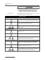
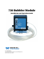
730 Bubbler Module Installation and Operation Guide Part #60-9003-063 Copyright © 1995. All rights reserved, Teledyne Isco Revision M, October 2013 Foreword This instruction manual is designed to help you gain a thorough understanding of the operation of the equipment. Teledyne Isco recommends that you read this manual completely before placing the equipment in service. Although Teledyne Isco designs reliability into all equipment, there is always the possibility of a malfunction. This manual may help in diagnosing and repairing the malfunction. If a problem persists, call or e-mail the Teledyne Isco Technical Service Department for assistance. Simple difficulties can often be diagnosed over the phone. If it is necessary to return the equipment to the factory for service, please follow the shipping instructions provided by the Customer Service Department, including the use of the Return Authorization Number specified. Be sure to include a note describing the malfunction. This will aid in the prompt repair and return of the equipment. Teledyne Isco welcomes suggestions that would improve the information presented in this manual or enhance the operation of the equipment itself. Teledyne Isco is continually improving its products and reserves the right to change product specifications, replacement parts, schematics, and instructions without notice. Contact Information Customer Service Phone: (800) 228-4373 (USA, Canada, Mexico) (402) 464-0231 (Outside North America) Fax: (402) 465-3022 Email: [email protected] Technical Support Phone: Email: Toll Free (866) 298-6174 (Samplers and Flow Meters) Toll Free (800) 775-2965 (Syringe Pumps and Liquid Chromatography) [email protected] Return equipment to: 4700 Superior Street, Lincoln, NE 68504-1398 Other Correspondence Mail to: P.O. Box 82531, Lincoln, NE 68501-2531 Email: [email protected] Revised September 2012 730 BubblerModule Safety 730 BubblerModule Safety General Warnings Before installing, operating, or maintaining this equipment, it is imperative that all hazards and preventive measures are fully understood. While specific hazards may vary according to location and application, take heed in the following general warnings: WARNING This instrument has not been certified for use in “hazardous locations” as defined by the National Electrical Code. WARNING Avoid hazardous practices! If you use this instrument in any way not specified in this manual, the protection provided by the instrument may be impaired; this will increase your risk of injury. AVERTISSEMENT Éviter les usages périlleux! Si vous utilisez cet instrument d’une manière autre que celles qui sont specifiées dans ce manuel, la protection fournie de l’instrument peut être affaiblie; cela augmentera votre risque de blessure. This product is often installed in confined spaces. Some examples of confined spaces are manholes, pipelines, digesters, and storage tanks. These spaces may become hazardous environments that can prove fatal for those unprepared. These spaces are governed by OSHA 1910.146 and require a permit before entering. Hazard Severity Levels This manual applies Hazard Severity Levels to the safety alerts, These three levels are described in the following sample alerts. CAUTION Cautions identify a potential hazard, which if not avoided, may result in minor or moderate injury. This category can also warn you of unsafe practices, or conditions that may cause property damage. WARNING Warnings identify a potentially hazardous condition, which if not avoided, could result in death or serious injury. iii 730 BubblerModule Safety DANGER DANGER – limited to the most extreme situations to identify an imminent hazard, which if not avoided, will result in death or serious injury. Hazard Symbols The equipment and this manual use symbols used to warn of hazards. The symbols are explained below. Hazard Symbols Warnings and Cautions The exclamation point within the triangle is a warning sign alerting you of important instructions in the instrument’s technical reference manual. The lightning flash and arrowhead within the triangle is a warning sign alerting you of “dangerous voltage” inside the product. Pinch point. These symbols warn you that your fingers or hands will be seriously injured if you place them between the moving parts of the mechanism near these symbols. Symboles de sécurité Ce symbole signale l’existence d’instructions importantes relatives au produit dans ce manuel. Ce symbole signale la présence d’un danger d’électocution. Risque de pincement. Ces symboles vous avertit que les mains ou les doigts seront blessés sérieusement si vous les mettez entre les éléments en mouvement du mécanisme près de ces symboles Warnungen und Vorsichtshinweise Das Ausrufezeichen in Dreieck ist ein Warnzeichen, das Sie darauf aufmerksam macht, daß wichtige Anleitungen zu diesem Handbuch gehören. Der gepfeilte Blitz im Dreieck ist ein Warnzeichen, das Sei vor “gefährlichen Spannungen” im Inneren des Produkts warnt. Vorsicht Quetschgefahr! Dieses Symbol warnt vor einer unmittelbar drohenden Verletzungsgefahr für Finger und Hände, wenn diese zwischen die beweglichen Teile des gekennzeichneten Gerätes geraten. iv 730 Bubbler Module Table of Contents Section 1 Introduction 1.1 1.2 1.3 1.4 1.5 1.6 Introduction . . . . . . . . . . . . . . . . . . . . . . . . . . . . . . . . . . . . . . . . . . . . . . . . . . . . . . . . Connecting to the Sampler . . . . . . . . . . . . . . . . . . . . . . . . . . . . . . . . . . . . . . . . . . . . Installation Checklist . . . . . . . . . . . . . . . . . . . . . . . . . . . . . . . . . . . . . . . . . . . . . . . . Calibrating the Bubbler Module. . . . . . . . . . . . . . . . . . . . . . . . . . . . . . . . . . . . . . . . Power Consumption . . . . . . . . . . . . . . . . . . . . . . . . . . . . . . . . . . . . . . . . . . . . . . . . . General Mounting Considerations for the Bubbler . . . . . . . . . . . . . . . . . . . . . . . . . 1.6.1 Line Length . . . . . . . . . . . . . . . . . . . . . . . . . . . . . . . . . . . . . . . . . . . . . . . . . . 1.6.2 Attach the Bubble Line to the Module . . . . . . . . . . . . . . . . . . . . . . . . . . . . . 1.6.3 Bubble Line Position in the Stream . . . . . . . . . . . . . . . . . . . . . . . . . . . . . . . 1.6.4 Bubble Line Extensions . . . . . . . . . . . . . . . . . . . . . . . . . . . . . . . . . . . . . . . . . 1.6.5 Installing the Bubble Line in a Primary Device . . . . . . . . . . . . . . . . . . . . . 1-1 1-2 1-2 1-2 1-2 1-3 1-3 1-3 1-3 1-4 1-4 Section 2 Programming the Module 2.1 Module Screens . . . . . . . . . . . . . . . . . . . . . . . . . . . . . . . . . . . . . . . . . . . . . . . . . . . . . 2.2 Programmed Enable . . . . . . . . . . . . . . . . . . . . . . . . . . . . . . . . . . . . . . . . . . . . . . . . . 2.3 Data Storage . . . . . . . . . . . . . . . . . . . . . . . . . . . . . . . . . . . . . . . . . . . . . . . . . . . . . . . 2.3.1 Recovering Module Data . . . . . . . . . . . . . . . . . . . . . . . . . . . . . . . . . . . . . . . . 2.4 Operation of the Bubbler System . . . . . . . . . . . . . . . . . . . . . . . . . . . . . . . . . . . . . . . 2.4.1 Purges . . . . . . . . . . . . . . . . . . . . . . . . . . . . . . . . . . . . . . . . . . . . . . . . . . . . . . . 2.4.2 Automatic Drift Compensation . . . . . . . . . . . . . . . . . . . . . . . . . . . . . . . . . . . 2.5 Alternative Flow Measurement Systems. . . . . . . . . . . . . . . . . . . . . . . . . . . . . . . . . 2-1 2-1 2-1 2-1 2-6 2-6 2-6 2-7 Section 3 Installation Methods 3.1 Installation in Round Pipes . . . . . . . . . . . . . . . . . . . . . . . . . . . . . . . . . . . . . . . . . . . 3.1.1 Flow Metering Inserts . . . . . . . . . . . . . . . . . . . . . . . . . . . . . . . . . . . . . . . . . . 3.1.2 Spring Rings . . . . . . . . . . . . . . . . . . . . . . . . . . . . . . . . . . . . . . . . . . . . . . . . . . 3.1.3 Scissors Rings . . . . . . . . . . . . . . . . . . . . . . . . . . . . . . . . . . . . . . . . . . . . . . . . 3.1.4 Street Level Installation System . . . . . . . . . . . . . . . . . . . . . . . . . . . . . . . . . 3.2 Other Installation Methods . . . . . . . . . . . . . . . . . . . . . . . . . . . . . . . . . . . . . . . . . . . 3.2.1 Rectangular, Trapezoidal, and Earthen Channels . . . . . . . . . . . . . . . . . . . 3.2.2 U-Channels . . . . . . . . . . . . . . . . . . . . . . . . . . . . . . . . . . . . . . . . . . . . . . . . . . 3.2.3 Non-Standard Installations . . . . . . . . . . . . . . . . . . . . . . . . . . . . . . . . . . . . . 3-1 3-1 3-2 3-3 3-5 3-5 3-5 3-5 3-5 Section 4 Maintenance 4.1 4.2 4.3 4.4 4.5 Desiccant Reactivation . . . . . . . . . . . . . . . . . . . . . . . . . . . . . . . . . . . . . . . . . . . . . . . Hydrophobic Filter . . . . . . . . . . . . . . . . . . . . . . . . . . . . . . . . . . . . . . . . . . . . . . . . . . Bubble Line Maintenance. . . . . . . . . . . . . . . . . . . . . . . . . . . . . . . . . . . . . . . . . . . . . Repairing The Module. . . . . . . . . . . . . . . . . . . . . . . . . . . . . . . . . . . . . . . . . . . . . . . . Flash Memory and Software Upgrades . . . . . . . . . . . . . . . . . . . . . . . . . . . . . . . . . . 4-1 4-2 4-2 4-2 4-2 Appendix A Accessories List v 730 Bubbler Module Table of Contents Appendix B Technical Specifications Appendix C Material Safety Data Sheets List of Figures 1-1 2-1 2-2 2-3 2-4 3-1 3-2 3-3 3-4 730 Module Mounted on Sampler . . . . . . . . . . . . . . . . . . . . . . . . . . . . . . . . . . . . . . Sample Reports . . . . . . . . . . . . . . . . . . . . . . . . . . . . . . . . . . . . . . . . . . . . . . . . . . . . Sampler Programming: 730 Module Screens . . . . . . . . . . . . . . . . . . . . . . . . . . . . . Sampler Programming: 730 Module Setup Screens . . . . . . . . . . . . . . . . . . . . . . . . Sampler Programming: 730 Module Quick View Screens . . . . . . . . . . . . . . . . . . . Spring Ring (6 to 15 inches) . . . . . . . . . . . . . . . . . . . . . . . . . . . . . . . . . . . . . . . . . . . Scissors Ring Adjustment . . . . . . . . . . . . . . . . . . . . . . . . . . . . . . . . . . . . . . . . . . . . Bubbler Carrier Mounted on Scissors Ring . . . . . . . . . . . . . . . . . . . . . . . . . . . . . . Typical installation methods . . . . . . . . . . . . . . . . . . . . . . . . . . . . . . . . . . . . . . . . . . 1-1 2-2 2-3 2-4 2-5 3-2 3-4 3-5 3-6 List of Tables 2-1 Flow Conversion Types . . . . . . . . . . . . . . . . . . . . . . . . . . . . . . . . . . . . . . . . . . . . . . 2-7 A-1 Parts and Accessories . . . . . . . . . . . . . . . . . . . . . . . . . . . . . . . . . . . . . . . . . . . . . . . A-1 B-1 Technical Specifications for the 730 Bubbler Module . . . . . . . . . . . . . . . . . . . . . . B-1 vi 730 Bubbler Module Section 1 Introduction 1.1 Introduction The 730 Bubbler Module is one of Teledyne Isco’s interchangeable modules for the Avalanche and 6700 Series Samplers. The module uses a differential pressure transducer and a flow of bubbles to measure liquid levels up to ten feet. The bubbler is unaffected by wind, fluctuations in air or liquid temperatures, turbulence, steam, foam on the surface, corrosive chemicals, debris, oil, floating grease, or lightning. The bubble line can be used in nearly any location with a known level-to-flow relationship. Figure 1-1 730 Module Mounted on Sampler WARNING The module has not been approved for use in hazardous locations as defined by the National Electrical Code. Installation of this module in a hazardous location may cause fire or explosion resulting in death, personal injury, or property damage. Before installing any device in a dangerous location, review safety precautions in your sampler manual. Check applicable guidelines, codes and regulations of federal, state, city, and county agencies. 1-1 730 Bubbler Module Section 1 Introduction 1.2 Connecting to the Sampler To install the module: 1. Turn the sampler off. 2. Remove the connector cap in the module bay and move it aside. 3. Slide the module into the bay. 4. Push against the module to be sure the connector is fully seated. To remove the module: 1. Turn the sampler off. 2. Press the silver button on top of the module and pull the module from the bay. 3. Replace the connector cap in the module bay. 1.3 Installation Checklist 1. Check the desiccant cartridge. Make sure the desiccant is active (blue in color) and remove the red cap. 2. Install the module and turn the sampler on. 3. Install the bubble line in the flow stream. 4. Connect the bubbler line to the module. 5. Program the sampler and calibrate the module’s level reading. 6. Run the program. Note You should install the module before turning the controller on. When the controller is turned on, it looks for a module. The controller will not recognize a newly installed module if it is not seen during this power-up routine. If you install a module while the controller is already on, turn the controller off and then on again to reconfigure the controller to use with the module. 1.4 Calibrating the Bubbler Module After the sampler, module, and bubble line have been installed at the site, calibrate the module by measuring the depth of the water and adjust the reading to match. It is possible to calibrate the module in a container of water. Use a bubble line of the same length as the one at the installation site to get an accurate and reliable calibration. If the level is a negative value, or if you need to toggle between positive and negative in the ADJUST LEVEL menu, press the "±" key before entering the numerical value. 1.5 Power Consumption 1-2 The 730 Module consumes a considerable amount of power. A nickel–cadmium battery may not be sufficient to finish a sample routine. For example, the battery should be expected to complete three sampling routines of 24 samples, each sample 200 ml, at one sample per hour with a 10 foot suction line and a 5 foot head. But if the routine is changed to 24 samples, 4 samples per bottle, each sample 250 ml, at 15 minute intervals, with the same suction line and head height, the battery does not have the 730 Bubbler Module Section 1 Introduction capacity to complete one routine. Teledyne Isco recommends using a lead–acid battery or a 913 or 923 power pack when using the 730 Bubbler Module. 1.6 General Mounting Considerations for the Bubbler This section contains some general information regarding the installation of the 730 module. More detailed installation information can be found in Section 3 Installation Methods. A standard 25 foot (7.6 m) length of 1/8" (0.32 cm) ID vinyl line is shipped with the module. We recommend that you do not use lengths longer than 25 feet. Please consult with the factory if your installation requires a nonstandard setup. 1.6.1 Line Length Cut the bubble line to the shortest usable length. This will minimize friction head effects in the line and also will reduce the amount of line exposed to cuts, kinks, etc. This will also improve the response time to changing levels and make the purge more effective. The bubble line should be routed and secured so that it does not disturb the flow. Do not kink the tubing or restrict the airflow by over-tightening the mounting hardware. 1.6.2 Attach the Bubble Line to the Module The vinyl bubble line attaches directly to the barbed fitting. Simply push the tubing over the fitting. Barbed Fitting Vinyl Bubble Line 1.6.3 Bubble Line Position in the Stream Recommended Bubble Outlet Depth The bubble line outlet does not need to be at the bottom of the stream. In fact, positioning the bubble line outlet above the bottom can be beneficial if the stream carries large amounts of solids or is subject to silting. The simplest installation method attaches the bubble line to the side of the flow stream with the bubble line outlet positioned below the lowest expected level. B Zero A A. The recommended depth ranges from the bottom to 1 inch below the zero level. B. This position would be unable to measure low levels through the primary device. To measure the liquid level down to the actual “zero” level of the primary device, Teledyne Isco recommends placing the bubble line outlet at least 1 to 2 inches (2.5 to 5.1 cm) below the primary device “zero” level to avoid measurement failures when the liquid level is even with the outlet. The module cannot accurately measure levels that are even with or below the bubble line outlet. 1-3 730 Bubbler Module Section 1 Introduction 1.6.4 Bubble Line Extensions For some applications, a stainless steel tube may be easier to install in the flow stream than the plastic bubble line because of its relative rigidity. The vinyl bubble line attaches by simply slipping the vinyl tube over the end of the extension. Contact your Teledyne Isco representative about purchasing a stainless steel bubble line extension. A copper extension to the bubble line is advantageous in applications where algae tends to grow in the bubble line. The copper salts released by the tubing are algicides that tend to inhibit the growth of algae. However, the copper tubing may not be compatible with the flow stream. Attach the copper bubble line extensions to the bubble line in the same way as the stainless steel extensions. 1.6.5 Installing the Bubble Line in a Primary Device Primary devices such as weirs or flumes will usually specify a head (level) measurement point. It is important to place the bubble line outlet at this point to convert levels to flow rates correctly. For more details about locating the head measurement point, refer to the Isco Open Channel Flow Measurement Handbook, or to information provided by the primary device manufacturer. Flume Bubble Line Fittings – B e c a u s e o f t h e v a r i e t y o f primary measuring devices and installations, no comprehensive bubble line installation instructions are practical. However, there are valid general observations on bubble line installation that can be made. You can have most flumes specified to include a bubbler fitting. In new construction, this is highly recommended. It may even be possible to modify an existing installation to include a permanent bubbler fitting. Stilling Wells – If the primary device includes a stilling well, you should install the bubble line in the stilling well. However, not all stilling wells are suitable for bubble line installation. If the well is subject to silting or buildup of foreign material, you should probably avoid it and mount the bubble line in the flow stream proper. Open Channel Installation – Attach the bubble line to the side of the flow channel or flume. Make the attachment so it causes a minimum amount of disturbance to the flow stream. If possible, cut a groove in the side of the channel, place the bubble line in the groove, and then grout over the groove. Alternately, you can attach the bubble line to the side of the channel, and then grout over the line to form smooth, sloped lead-in and lead-out surfaces. However, you may simply attach the bubble line to the side of the channel or the upstream side of a weir. Note When installing the bubble line in a high-velocity flow stream (exceeding 5 ft/sec or 1.5 m/sec), please consult with the Teledyne Isco Customer Service Department for recommendations. 1-4 730 Bubbler Module Section 2 Programming the Module 2.1 Module Screens When the controller is configured with the module, it adds the necessary screens for programming. The screens appear on the following pages in Figures 2-2 through 2-4. These figures outline the steps for module programming and calibration. For sampler programming and general programming information, refer to the sampler manual. 2.2 Programmed Enable When the 730 Module is installed, additional sampler enable options are available. If programmed for LEVEL ONLY the option will be LEVEL. If programmed for FLOW METER the options will be LEVEL and FLOW. For more information about programmed enables, refer to the sampler manual. 2.3 Data Storage When the sampler is configured for use with the module, a memory partition is reserved. The module readings are stored in this sampler memory partition. For more information on data storage and partition management, see the sampler manual. 2.3.1 Recovering Module Data The stored module data can be collected or viewed as “reports.” Three of the sampler reports contain module information, and are shown in Figure 2-1. Refer to the Sampler Instruction Manual for collecting and reading the reports. Note An * (asterisk) appears next to the reading if the module was unable to take a reading. If an asterisk appears, the reading displayed is the last available reading. 2-1 730 Bubbler Module Section 2 Programming the Module Summary Report Settings Report Flow Summary - 13 SEP-03 (FR) SAMPLER ID# 11343009 15:25 13-SEP-03 *********** PROGRAM SETTINGS *********** ---------SITE DESCRIPTION: "FACTORY " ---------UNITS SELECTED: LENGTH: ft ---------UNITS SELECTED: FLOW RATE: cfs FLOW VOLUME: Mgal ---------BUBBLER MODULE: WEIR 90 V-NOTCH ---------1 MINUTE DATA INTERVAL ---------24, 1000 ml BTLS 10 ft SUCTION LINE ---------PACING: TIME, EVERY 0 HOURS, 15 MINUTES ---------DISTRIBUTION: SEQUENTIAL 200 ml SAMPLES ---------5 MINUTE DELAY TO FIRST SAMPLE RUN PROGRAM ONCE --------------------------------------- Combined Report SAMPLER ID# 11343009 15:25 13-SEP-03 BUBBLER MODULE: 638324458 *********** COMBINED RESULTS *********** SITE: FACTORY Program Started at 08:41 SAT 13-SEP-03 Nominal Sample Volume = 200 ml FLOW TOTAL RATE FLOW SAMPLE BOTTLE TIME cfs Mgal ------- ------ ---- --------- ---------1 1 08:41 2.495 0.000000 1 2 08:56 2.576 0.016941 1 3 09:11 2.666 0.034698 1 4 09:26 2.773 0.052914 1 5 09:41 2.773 0.071707 1 6 09:56 2.798 0.090520 1 7 10:11 2.798 0.109314 1 8 10:26 2.798 0.128112 1 9 10:41 2.751 0.146911 1 10 10:56 2.773 0.165698 1 11 11:11 2.798 0.184556 1 12 11:26 3.728 0.206933 1 13 11:41 3.728 0.232024 1 14 11:56 3.728 0.257108 1 15 12:11 3.728 0.282171 1 16 12:26 5.273 0.317318 1 17 12:41 5.239 0.352755 1 18 12:56 6.651 0.396903 1 19 13:11 6.651 0.441689 1 20 13:26 6.651 0.486476 1 21 13:41 6.651 0.531238 1 22 13:56 6.651 0.575999 1 23 14:11 3.404 0.611500 1 24 14:26 3.425 0.634426 ---------------------------------------- Figure 2-1 Sample Reports 2-2 Flow at "FACTORY " Site On 13-SEP-03 BUBBLER MODULE: 638324458 Day's Flow: 0.678964 Mgal Average Flow Rate: 3.466 cfs 12:45 Maximum Flow Rate: 6.689 cfs 14:49 Minumum Flow Rate: 1.442 cfs 00:00-01:00: 01:00-02:00: 02:00-03:00: 03:00-04:00: 04:00-05:00: 05:00-06:00: 06:00-07:00: 07:00-08:00: 08:00-09:00: 09:00-10:00: 10:00-11:00: 11:00-12:00: Hourly Average Flow Rate: NO DATA 12:00-13:00: NO DATA 13:00-14:00: NO DATA 14:00-15:00: NO DATA 15:00-16:00: NO DATA 16:00-17:00: NO DATA 17:00-18:00: NO DATA 18:00-19:00: BEGIN DATA 19:00-20:00: 2.519 cfs 20:00-21:00: 2.747 cfs 21:00-22:00: 2.791 cfs 22:00-23:00: 3.456 cfs 23:00-24:00: * - - - + - - - + + I I I I 10.00 + I I I I 8.00 + I I I I 6.00 + I I I I 4.00 + I I I I # 2.00 + # I # I # I # I # 0.00 + # * - - - + - - - + Hour Ending: 04:00 08:00 12.00 5.385 cfs 6.651 cfs 2.591 cfs 1.593 cfs END DATA NO DATA NO DATA NO DATA NO DATA NO DATA NO DATA NO DATA - - + - - - + - - - + - - - + * + I I I I + I I I I + I I I # I # + # I # # I # # I # # I # # + # # I # # # I # # # I # # # # # # I # # # # # # + # # # # # # I # # # # # # # I # # # # # # # I # # # # # # # I # # # # # # # + - - + - - - + - - - + - - - + * 12:00 16:00 20:00 24:00 Units are 'cfs' 730 Bubbler Module Section 2 Programming the Module MODULE INSERTED-DOWNLOAD DATA NOW OR LOSE ALL DATA! DONE This screen appears only when a module has been changed or if the module was unplugged while the sampler was powered. If NO is selected, the sampler responds as if there is no module. Standard 6712 SAMPLER STANDARD PROGRAMMING FOR HELP AT ANY SCREEN PRESS ? KEY Extended 6712 SAMPLER EXTENDED PROGRAMMING FOR HELP AT ANY SCREEN PRESS ? KEY RUN PROGRAM VIEW REPORT OTHER FUNCTIONS RUN "EXTENDED 1' PROGRAM VIEW REPORT OTHER FUNCTIONS See sampler manual. SITE DESCRIPTION "FACTORY" CHANGE? YES NO PROGRAM NAME" "EXTENDED 1" CHANGE? YES NO See sampler manual. SELECTED UNITS FOR LENGTH: ft m NO PROGRAM MODULE? YES NO SELECT UNITS FOR FLOW RATE: cfs gps gpm Mgd lps m3s m3h m3d Note: SELECT UNITS FOR FLOW VOLUME: cf gal Mgal m3 lit To program the module or run a program that requires a module, you must plug in the module before turning on the 6712 controller. YES See Figure 2-3, Module Setup. NEW MODULE SETUP -DOWNLOAD DATA NOW OR LOSE ALL DATA! DONE CURRENT LEVEL IS __.__ ft ADJUST LEVEL TO __.__ ft DATA STORAGE INTERVAL IN MINUTES 1 2 5 10 15 30 If applicable. This screen appears only when a selection is changed. Selecting NO will cause the sampler to not accept the module setup changes. __.__ ft ARE YOU SURE? YES NO INTERVAL CHANGED -DOWNLOAD DATA NOW OR LOSE ALL DATA! DONE If applicable. This screen appears only when the adjustment differs from the current reading by more than 0.5 ft. If applicable. This screen appears only when the interval is changed. If NO was selected the storage interval will not change. Continue with sampler programming sequence (see sampler manual). Figure 2-2 Sampler Programming: 730 Module Screens 2-3 730 Bubbler Module Section 2 Programming the Module Module Setup V-NOTCH RECTANGULAR CIPOLLETTI V-NOTCH WEIR ANGLE: 120 90 60 45 30 22.5 MODE OF OPERATION: FLOWMETER LEVEL ONLY END CONTRACTIONS ON RECTANGULAR WEIR? YES NO Weir WEIR FLUME DATA POINTS EQUATION MANNING FLOW-INSERT ENTER CREST LENGTH: _.__ ft (min, max) Flume PALMER-BOWLUS PARSHALL TRAPEZOIDAL H EDIT DATA POINTS CLEAR DATA SET SELECT NEW SET CHANGE NAME PALMER-BOWLUS SIZE: 4" 6" 8" 10" 12" 15" 18" 21" 24" 27" 30" 48" (ft, cfs) 1. (____.____) 2. (____,____) 3. (____,____) PARSHALL SIZE: 1" 2" 3" 6" 9" 1' 1.5' 2' 3' 4' 5' 6' 8' 10' 12' TRAPEZOIDAL SIZE: 2" 45 WSC 12" 45 SRCRC LG 60 V PLEASE WAIT! ...SORTING DATA CLEAR DATA SET! ARE YOU SURE YES NO "DATA "DATA "DATA "DATA SET SET SET SET 1" 2" 3" 4" DATA SET __________ ABCDEFGHIJKLMNOPQRST UVWXYZ -&"0123456789 BACKUP DONE Flow-Insert WEIR/ORIFICE TYPE V-NOTCH ROUND FLOW INSERT SIZE: 6" 8" 10" 12" Manning ROUND PIPE U-CHANNEL RECTANGULAR CHANNEL TRAPEZOIDAL CHANNEL SLOPE= _.____ ROUGHNESS= _.___ DIAMETER = __.___ft SLOPE= _.____ ROUGHNESS= _.___ TOP WIDTH= __.___ft BOTTOM= __.___ft Continue SLOPE = _.____ ROUGHNESS= _.___ TOP WIDTH= __.___ft BOTTOM= __.___ft Figure 2-3 Sampler Programming: 730 Module Setup Screens 2-4 H FLUME SIZE: 0.5' 0.75' 1.0' 2.0' 2.5' 3.0' 4.5' INVALID ENTRY! ...DUPLICATE DEPTH Stop SAVE CHANGES? YES NO 730 Bubbler Module Section 2 Programming the Module MODULE INSERTED-DOWNLOAD DATA NOW OR LOSE ALL DATA! DONE This screen appears only when a module has been changed or if the module was unplugged while the sampler was powered. If NO is selected, the sampler responds as if there is no module. Standard Extended 6712 SAMPLER STANDARD PROGRAMMING FOR HELP AT ANY SCREEN PRESS ? KEY Note: 6712 SAMPLER EXTENDED PROGRAMMING FOR HELP AT ANY SCREEN PRESS ? KEY RUN PROGRAM VIEW REPORT OTHER FUNCTIONS To program the module or run a program that requires a module, you must plug in the module before turning on the 6712 controller. RUN "EXTENDED 1" PROGRAM VIEW REPORT OTHER FUNCTIONS See sampler manual. SITE DESCRIPTION: "FACTORY" UNITS SELECTED: LENGTH: ft UNITS SELECTED: FLOW RATE: cfs FLOW VOLUME:Mgal PROGRAM NAME: "EXTENDED 1" SITE DESCRIPTION "FACTORY See sampler manual. SELECTED UNITS FOR LENGTH: ft m SELECT UNITS FOR FLOW RATE: cfs gps gpm Mgd lps m3s m3h m3d SELECT UNITS FOR FLOW VOLUME: cf gal Mgal m3 lit BUBBLER MODULE WEIR 90 V-NOTCH See Figure 2-3, Module Setup. CURRENT LEVEL IS __.__ft CURRENT LEVEL IS __.__ ft ADJUST LEVEL TO __.__ ft __ MINUTE DATA INTERVAL DATA STORAGE INTERVAL IN MINUTES: 1 2 5 10 15 30 __.__ ft ARE YOU SURE? YES NO Continue with the sampler programming sequence (see sampler manual). Figure 2-4 Sampler Programming: 730 Module Quick View Screens 2-5 730 Bubbler Module Section 2 Programming the Module 2.4 Operation of the Bubbler System When measuring flow rate, the module is used with a primary measuring device (typically a weir or a flume) or other open channel flow arrangement where a known relationship exists between level and flow rate (refer to Table 2-1 Flow Conversion Types). The level measuring device is a bubbler which measures the liquid level in the flow stream. The level reading is converted into a properly scaled flow rate value. The module contains microprocessor-controlled circuitry to calculate level from the signals produced by the pressure transducer, and communicate with the sampler controller. The module’s bubbler system works as follows: A small compressor pumps air into a reservoir. This air is slowly released by an orifice into a bubble line. The other end of this tube is submerged in the flow stream. Inside the module, the bubble line also connects to one side of a differential pressure transducer. As air is released slowly into the bubble line by the orifice, pressure builds inside the line to force the air out of the line into the flow stream. When there is enough pressure to counteract the hydrostatic pressure of the flow stream, a bubble will be forced from the end of the line. The amount of pressure required to force the bubble from the end of the line is directly dependent on the hydrostatic pressure of the flow stream over the end of the bubble line. The pressure transducer inside the module senses this pressure and converts it into an electrical signal that the module converts into level. The sampler controller then calculates flow rate and total flow from the level measurement and lookup tables for the primary device you are using. The module produces the pressurized air supply, regulates the rate of air to the bubbler tube, measures the pressure in the bubbler tube, purges the air line, compensates for drift, and other functions. 2.4.1 Purges Periodically, the module releases a high pressure, unregulated burst of air directly into the bubble line. This is done to clear the line and prevent any buildup of debris at the bubble line outlet. 2.4.2 Automatic Drift Compensation The module measures the output of the pressure transducer at zero pressure. When the module is first turned on, and every 15 minutes after that, the processor actuates the automatic drift compensation valve, which connects the input port of the pressure transducer to the reference port. With the two ports connected, it then measures the output offset. The module stores this offset reading in memory and uses it in level calculations. The repetition of this process causes any pressure transducer or amplifier drift to cancel out, eliminating the most significant cause of drift, especially when operating at low water levels. 2-6 730 Bubbler Module Section 2 Programming the Module The following table contains programming information for each of the conversion types. Table 2-1 Flow Conversion Types Conversion Type Weir Flume Device, Formula, or Table Size or Parameters V- Notch Weir 22.5, 30, 45, 60, 90, 120 degrees Rectangular Weir with End Contractions Crest length Rectangular Weir without End Contractions Crest length Cipoletti Weir Crest length Palmer-Bowlus Flume 4, 6, 8, 10, 12, 15, 18, 21, 24, 27, 30, 48 inches Parshall Flume 1, 2, 3, 6, 9 inches 1, 1.5, 2, 3, 4, 5, 6, 8, 10, 12 feet Trapezoidal Flume Large 60-degree V 2-inch, 45-degree WSC 12-inch, 45-degree SRCRC “H” Flume Equation Q=axH b+c 0.5, 0.75, 1, 1.5, 2, 2.5, 3, 4.5 feet. x Hd Q = flow H = head a, b, c, & d = entered values Data Points User-developed tables for level-to-flow rate. Includes data points from a user derived flow profile. 3 to 50 data points Manning Equation Round Pipe Slope, Roughness, Diameter U-Channel Pipe Slope, Roughness, Width Rectangular Pipe Slope, Roughness, Width Trapezoidal Slope, Roughness, Bottom Width, Top Width V-Notch 6, 8, 10, 12 inch Round 6, 8, 10, 12 inch Flow Metering Insert 2.5 Alternative Flow Measurement Systems Because of the characteristics of bubbler flow measurement, there may be some installations where the bubbler method is either unreliable or inaccurate. In these instances, it is worthwhile to consider using an alternate method of flow measurement. In addition to the 730 Module, Teledyne Isco offers three other types of plug-and-play flow modules in the 700 Series: the 720 Submerged Probe Module, the 710 Ultrasonic Module, and the 750 Area-Velocity Module. Information about these flow modules is available from the factory. Call for more information or visit our Web site at www.isco.com. 2-7 730 Bubbler Module Section 2 Programming the Module 2-8 730 Bubbler Module Section 3 Installation Methods The bubble line may be installed in many different channel types, which are summarized here. For more detailed information about mounting options, consult your Isco Mounting Rings Installation and Operation Guide. See Figure 3-4 for examples of the mounting methods described in this section. 3.1 Installation in Round Pipes Teledyne Isco offers four systems for installing bubble line in round pipes: • Flow Metering Inserts • Isco Spring Rings (for pipe diameters of 15 inches or less) • Scissors Rings (for pipe diameters from 16 to 80 inches) • Street Level Installation System 3.1.1 Flow Metering Inserts Flow metering inserts are available for use with the module that you can temporarily install inside round pipe sewers and flow streams to create a primary device inside the pipe. These inserts are available to fit 6", 8", 10", and 12" pipes and install from street level. The inserts create a restriction in the flow stream and may cause clogging. Where this could be a problem, we suggest using one of the other three installation systems instead. Because the flow metering inserts are installed from street level, it is not possible to measure the level. Instead, you must set the level to zero before installing the flow metering insert in the pipe. Set the level to zero using the following instructions: 1. Install the module in the Sampler and remove the red cap from the desiccant cartridge. 2. Assemble the flow metering insert to the length that will be installed. 3. Attach the bubble line to the module. The inside of the bubble line must be dry and unobstructed. 4. Turn on the sampler and wait 2 to 3 minutes to allow the bubbler’s air system to stabilize. 5. Select Program from the sampler’s main menu and step through the screens until the “Current Level” screen appears. (Detailed programming instructions appear in the sampler manual.) 6. Adjust the level to read zero (0.00 feet or meters). 3-1 730 Bubbler Module Section 3 Installation Methods You may exit the programming after setting the current level to zero. When you install the flow metering insert, the bubbler module will then provide liquid level readings based on this zero level. 7. Proceed with installing the insert into the pipe. 3.1.2 Spring Rings Consult your Isco Mounting Rings instruction manual for detailed hardware information. Stainless steel spring rings simplify probe installation in 6 to 15 inch round pipes. Teledyne Isco offers five diameter sizes: 6, 8, 10, 12, and 15 inches (15.2, 20.3, 25.4, 30.5, and 38 cm). A typical spring ring is shown in Figure 3-1. This self-expanding device compresses to slide into a pipe. When released, the ring secures itself against the wall with an inherent outward force. Figure 3-1 Spring Ring (6 to 15 inches) Preparing the Spring Ring: First attach the bubble line to the bubbler carrier assembly (contact your Teledyne Isco representative to purchase the bubbler carrier). Then fit the carrier onto the mounting tabs of the ring, making sure the tabs completely engage the slots in the carrier. This method of attaching the bubble line to the ring allows for easy removal in case service is needed later. Bubble Line Carrier 3-2 730 Bubbler Module Section 3 Installation Methods Route the vinyl bubble line away from the carrier and along the spring ring’s edge with holes. Secure the line in position by placing plastic ties through the holes and then locking them around the line. To prevent debris from collecting, attach the line so that it offers as little resistance to the flow as possible. Avoid loops or slack sections. Attach it neatly and closely to the spring ring. Plastic Ties Flo w Spring Ring Preparation Installing the Spring Ring: After the bubble line and carrier have been attached to the spring ring, the actual installation procedure is fairly simple. First, lower the spring ring assembly into the area of the pipe. Next, grasp the spring ring and compress it into a tight circle. Then push the ring up into the pipe the desired distance. When you have the ring positioned, release the ring, allowing it to expand outward. It may be necessary to rotate the ring to position the bubble line outlet in the bottom center of the pipe. This completes the installation. Under conditions of high velocity (greater than five feet per second or 1.5 meters per second), the spring ring may not have sufficient outward force to keep it tight against the pipe. The flow could lift the ring off the bottom of the pipe, or even carry it downstream. This problem is more prevalent in the larger diameter pipes (10, 12, and 15 inch) and in pipes with a smooth inner surface (plastic, for example). If any of these conditions are present, or if movement of the spring ring is detected or suspected, you must anchor the ring in place. You can do this by shooting studs through the ring into the pipe or by other appropriate means. In some cases, it may be sufficient to increase the outward force of the ring by bending it into a less rounded shape. 3.1.3 Scissors Rings Consult your Isco Mounting Rings instruction manual for detailed hardware information. For pipes larger than 15" in diameter, Teledyne Isco offers the adjustable Scissors Ring (also known as the Universal Mounting Ring). This device consists of two or more metal strips that lock together with tabs to form a single assembly. There is a base section where the sensors are mounted, one or more extension sections (usually), and a scissors section at the top that expands the entire assembly and tightens it inside the pipe. The scissors mechanism includes a long screw that increases the width as it is tightened. The assembled rings fit pipe diameters from 16" to 80". Secure the unit in place by tightening the scissors mechanism with a 5/8" socket wrench or other suitable tool. Ring sections are .040" thick half-hard 301 stainless steel sheet. All other parts are also stainless steel, except for the plastic cable ties in the hardware kit. Each extension, 1, 2, 3, and 4, adds 9.0", 21.5", 31.5", or 41.5", respectively, to the circumference of the ring. Used alone, the base section fits pipe that is approximately 16" to 18" in 3-3 730 Bubbler Module Section 3 Installation Methods diameter. The 9.0" (the smallest) extension exists so that in larger pipe sizes, where large variations in circumference can occur, you can use one or two of these extensions to take up or remove slack, to bring the scissors mechanism into a position where it can be effectively tightened. Mounting ring kits are available for different pipe sizes. A kit is also available for partial pipe applications (see your Isco Mounting Rings Installation and Operation Guide). For a listing of part numbers and ordering information, see Appendix A. To prevent debris from catching on the cable, it is important to attach the cable to the mounting ring so it offers as little resistance to the flow as possible. Attach the sensor cable to the downstream edge of the ring, using the self-locking plastic ties supplied with the ring. Place the ties through the holes in the edge of the mounting ring and then lock them around the cable. Scissors Assembly Extensions Base Section Figure 3-2 Scissors Ring Adjustment 3-4 Tightening the scissors assembly expands the ring to press firmly against the pipe wall, securing the ring. 730 Bubbler Module Section 3 Installation Methods Figure 3-3 Bubbler Carrier Mounted on Scissors Ring 3.1.4 Street Level Installation System 3.2 Other Installation Methods The Street Level Installation System provides a way to install the probe in a round pipe without entering a manhole. This system uses multi-section poles and expansion rings that fit 6, 8, 10, 12, and 15 inch round pipes in manholes as deep as 15feet. The system includes an instruction manual. Teledyne Isco’s mounting hardware can be installed or adapted for use in many channels. The paragraphs below list additional bubble line installation methods. 3.2.1 Rectangular, Trapezoidal, and Earthen Channels Teledyne Isco offers the Sensor Mounting Plate for these channels. The stainless steel plate has tabs to mount up to three sensors. The bubble line carrier also attaches to the tabs (see figure in the left margin). It is secured in concrete channels by driving studs into the channel bottom and bolting the plate to the studs. In an earthen channel, the plate can be held in place by driving in stakes. Sensor Mounting Plate 3.2.2 U-Channels It is possible to mount the bubble line retainer in a U-channel with a scissors ring base section. Attach the base section to the channel wall with studs fired from a power-activated stud gun. Consult the factory for more information, if you must mount the bubble line in a U-channel. 3.2.3 Non-Standard Installations If you are not using a primary device, or if your primary device is not listed in Figure 3-4, please consult with the Teledyne Isco Customer Service Department for installation recommendations. 3-5 730 Bubbler Module Section 3 Installation Methods Round Pipe Weir Sensor Mounting Plate Spring Ring Parshall Flume Line attached to integral bubble tube Round Pipe Street Level Installation System Metering Insert Round Pipe Figure 3-4 Typical installation methods 3-6 730 Bubbler Module Section 4 Maintenance The 730 Bubbler Module has no user serviceable parts. It is completely sealed to protect the internal components. If you think the module requires repair, contact Teledyne Isco’s Customer Service Department. 4.1 Desiccant Reactivation A cartridge on the side of the module dries the air inside the module and probe reference line. It contains a silica gel desiccant with a color indicator that changes from blue to pink, or yellow to green, when saturated. Pink or green desiccant cannot remove moisture and must be replaced or reactivated. A saturated desiccator will let moisture into the bubbler system, which can cause several undesirable effects, including: · The moisture may block internal tubing and cause reading errors. · The air in many installations contains fumes that will form acids in the presence of moisture. These acids may corrode internal components. · At temperatures near or below freezing, there could be permanent damage if ice forms inside the air pump. To reactivate the desiccant, pour the desiccant out of the cartridge into a heat-resistant container. Never heat the plastic cartridge; it will melt. Heat the silica gel in a vented convection oven at 212° to 350° F (100° to 175° C) for two to three hours, or until the blue or yellow color returns. Allow the desiccant to cool and then refill the cartridge. CAUTION Desiccant may produce irritating fumes when heated. Observe the following precautions: • Use a vented oven in a well-ventilated room. • Do not remain in the room while the regeneration is taking place. • Use the recommended temperature. Avoid heating the desiccant at higher than recommended temperatures. The desiccant’s ability to remove moisture may lessen with each saturation/reactivation cycle, resulting in a need for more frequent service. After several cycles, the desiccant may no longer be effective as it saturates too quickly. At this point, replace the desiccant. 4-1 730 Bubbler Module Section 4 Maintenance The filters in the end caps keep small pieces of the desiccant material from falling out of the cartridge. When the filters become soiled, clean with dish soap and water, then allow to dry. 4.2 Hydrophobic Filter Fitting Hydrophobic Filter The hydrophobic filter prevents water from entering the module. Any amount of water will plug the filter. If the filter becomes plugged replace it. To remove the filter, turn it counterclockwise while making sure the black fitting does not rotate. Replacement hydrophobic filters, Isco P/N 60-2005-003, are available from Teledyne Isco. 4.3 Bubble Line Maintenance Periodically inspect the bubble line to make sure that it has not become kinked or damaged in any way. If you find damage to the bubble line, replace it. A leaking or obstructed line will cause inaccurate level readings and lower battery life. (The pump must run more frequently.) If you need to replace the bubble line, install a new line the same way you installed the original. Generally, the new line should be the same length as the old. If you replace the bubble line or if you change the outlet either by cutting off the tip or by installing a bubble line extension, you must recalibrate the level. Inspect the outlet of the bubble line regularly for any signs of clogging. Sediment or debris from the flow stream and algae can all clog the line. If the line is blocked, you can either clean it out, or simply cut off the tip. If algae growth is a problem, consider using a copper bubble line extension. The copper salts formed on a copper line will prevent algae growth. 4.4 Repairing The Module The module has no user-serviceable parts. Its case is completely sealed to protect the internal components. To repair the unit, the case must be broken open and replaced. If you think your module requires repair, contact Teledyne Isco’s Customer Service Department for information on returning it to the factory. 4.5 Flash Memory and Software Upgrades The module has Flash memory to store its software. With Flash technology, you can upgrade your module’s software without sending it back to the factory or replacing a chip. To update the module software, install the module in a sampler. Then connect the sampler power source and turn the sampler on. Connect the sampler to a computer and follow the instructions received with your Flash Update program. 4-2 730 Bubbler Module Appendix A Accessories List The following table contains information about replacement parts and accessories. Replacement parts and accessories can be purchased by contacting Teledyne Isco’s Customer Service Department. Table A-1 Parts and Accessories Part Description Part Number 730 Bubbler Module (includes module, bubble line, and manual) 68-6700-050 Bubble Line 25’ 60-9003-281 Bulk Bubble Line 100’ 68-1700-003 Hose Barb for Bubble Line Connection 60-9003-426 4’ SST Extension 60-1873-043 Bubbler Carrier Assembly 60-3204-007 Accessory Package (includes desiccator cartridge and hydrophobic filter) 60-9004-144 Replacement Hydrophobic Filter 60-2005-003 Isco Open Channel Flow Measurement Handbook 60-3003-041 Desiccator Cartridge 60-9004-105 1-lb Refill Bottle of Desiccant 60-2004-233 Spring Ring - 6" Dia. 68-3200-007 Spring Ring - 8" Dia. 68-3200-008 Spring Ring - 10" Dia. 68-3200-009 Spring Ring - 12" Dia. 68-3200-010 Spring Ring - 15" Dia. 68-3200-011 (Each spring ring includes plastic ties to fasten the bubble line.) Scissors Ring for 16" - 23" Pipe 68-3000-042 Scissors Ring for 16" - 36" Pipe 68-3000-043 Scissors Ring for 39" - 43" Pipe 68-3000-044 Scissors Ring for 45" - 49" Pipe 68-3000-045 Scissors Ring for 58" to 62" Pipe 68-3000-046 Scissors Ring for 72" Pipe 68-3000-047 Scissors Ring for 16" - 80" Pipe 68-3000-048 (Each scissors ring includes a base section, scissors mechanism, extensions, plastic ties, and installation instructions) Mounting Ring Base Assembly (Includes plastic ties and installation instructions) 60-3004-169 A-1 730 Bubbler Module Appendix A Accessories List Table A-1 Parts and Accessories (Continued) Scissors Mechanism 60-3004-170 Pair of 7.5" Extensions for Scissors Ring 68-3000-038 Pair of 20" Extensions for Scissors Ring 68-3000-039 Pair of 30" Extensions for Scissors Ring 68-3000-040 Pair of 40" Extensions for Scissors Ring 68-3000-041 Part Description Part Number Street Level Installation System Multi-Section Pole. (Includes instruction manual. To complete your system, you must also order a Street Level Mounting Ring.) 60-3204-012 Street Level Mounting Ring for 6" diameter pipe 60-3204-014 Street Level Mounting Ring for 8" diameter pipe 60-3204-015 Street Level Mounting Ring for 10" diameter pipe 60-3204-016 Street Level Mounting Ring for 12" diameter pipe 60-3204-017 Street Level Mounting Ring for 15" diameter pipe 60-3204-018 6" Metering Insert 68-3230-005 8" Metering Insert 68-3230-006 10" Metering Insert 68-3230-007 12" Metering Insert 68-3230-008 (Metering inserts include poles, pump, hose, attachable 60 degree V-notch weir plate, and instruction manual.) Probe Extension 68-3200-012 Sensor Mounting Plate 60-3253077 A-2 730 Bubbler Module Appendix B Technical Specifications The following table contains information covering the technical specifications of the 730 Module. General Notes: 1. All weights may vary ± 0.2 lb (± 0.1 kg). 2. All lengths may vary ± 0.25 inch (± 0.64 cm). Table B-1 Technical Specifications for the 730 Bubbler Module Item Specification Weight 1.5 lbs. (0.7 kg) Dimensions 4.9 x 5.7 x 2.0 inches (12.4 x 14.5 x 5.1 cm) Material Polystyrene Operational Temperature 32° to 120° F (0° to 49° C) Storage Temperature 0° to 140° F (-18° to 60° C) Enclosure NEMA 4X and 6, IP67 Power Provided by the sampler. Memory Nonvolatile programmable Flash; can be field updated through the sampler. Readings Programmable through the sampler at 1, 2, 5, 10, 15, and 30 minute intervals. Bubble Line Vinyl: Range 0.010 ft (0.003 m) minimum water level above bubble outlet. 10 ft. (3.038 m) maximum water level above bubble outlet. Level Measurement Accuracy 0.01 to 5.0 ft: inside diameter: 1/8 “ (0.32 cm) length: 25 feet (7.6 cm) 0.01 ft 0.01 to 10.0 ft: 0.035 ft 0.003 to 1.524 m: 0.003 m 0.003 to 3.048 m: 0.011 m Includes linearlity, repeatability, and hysteresis at 77° F (25° C). Does not include the temperature coefficient. Level is the distance between the bubble outlet and the liquid surface. Temperature Coefficient 0.01 to 5.0 ft: ± 0.0006 x level in feet x temperature change from 77° F 0.01 to 10.0 ft: ± 0.0005 x level in feet x temperature change from 77° F 0.003 to 1.524 m: ± 0.00108 x level in meters x temperature change from 25° C 0.003 to 3.048 m: ± 0.0009 x level in meters x temperature change from 25° C Temperature coefficient is the maximum error within the operating temperature range per degree of temperature change. Add to Level Accuracy. Automatic Drift Correction ±0.002 ft (±0.0006 m) at 15 minute intervals Level Resolution 0.001 ft (0.0003 m) B-1 730 Bubbler Module Appendix B Technical Specifications B-2 730 Bubbler Module Appendix C Material Safety Data Sheets This appendix provides Material Safety Data Sheets for the desiccant used by the 730 Bubbler Module. Teledyne Isco cannot guarantee the accuracy of the data. Specific questions regarding the use and handling of the products should be directed to the manufacturer listed on the MSDS. C-1 730 Bubbler Module Appendix C Material Safety Data Sheets '4 ,"'&@5 < &$)("/'4 "!"/$$'/ &","& "$"$ -#$#-"'/*& &","& "$"$ "&#-'''(# -,+" )%%!&/ L@6GCF6AHA6GE?? L@6GCF6AHA6GE?? &,**$'$'*('*,"'& G??-++/13-",@?@ *#" 3 E??EG $(!'&5 05 L@6GCF6AHA6GE?? L@6GCF6AHA6GE?@ ,"'&A5 < )"&'/@BCB8HG8A3FF8?H8G $!)!&$&")!/"A9&ALA?@CC ,"'&B5 $(#(!!((' #!($#/1-+*1&++&"**",,"'&,'%-'-+%%*&+3&'+&,!*',61%(,'%+ %1"&$-'- !"& 3+'*,!*',3&/!2"& 6 #'($#/'.*+,+0(,6 #$#((/1-+"**",,"'&/",!*1&++&*+"'&6 -$#((/1-+"**",,"'&3*&++&("&6 &$#,%$')&/(,0('+-*%1-++1%(,'%++"%"$*,',!'+$"+,'*-,,+6 1&,!,"%'*(!'-++"$"'+&',(*'-+"$"'+"+6 ,"'&C5 -$#((/!#'*&*%'.&1'&,,$&++6 &+''&,,3"%%",$1$-+!1+/,! ($&,1'/,*'*,$+,@D%"&-,+6,%"$,,&,"'&""**",,"'&'-*+6 #$#((/+!/",!+'(&/,*6'.*,!"**",,+#"&/",!&%'$$"&,6,%"$ ,,&,"'&""**",,"'&.$'(+0 #'($#/".+.*$ $+++'/,*,'*"&#,'"$-,6 $* %'-&,+/*+/$$'/3 , %"$."6 #!($#/ "&!$3*%'.,'*+!"*6 *,!"& "+""-$,3 ,%"$,,&,"'&6 ,"'&D5 < &/','&+"*,'"*!2*6 ,%!$'$#/','&+"*,'&0($'+"'&!2*6 &(## #'(&)($#'/+&1%&++-",$'*0,"& -"+!"& +-**'&"& "*6 %!"& '/+(*',,".$',!"& &*,!"& )-"(%&,((*'(*",'*+-**'&"& "*6 $'$'*('*,"'& C-2 %+++ (@ 730 Bubbler Module Appendix C Material Safety Data Sheets ,"'&E5 "!!%!!/+((*'(*",,''$+,'(-,,!+("$$+'$""&'&.&"&,/+,"+('+$'&,"&*6+ *+("*,'*1(*',,"'&&1(*',,"'&6 &%!!/++!'.$,'(-,,!%,*"$"&,''&.&"&,/+,"+('+$'&,"&*6--%"& '* /,+/("& %1-+,'.'"-+,"+(*+$6+*+("*,'*1(*',,"'&&1(*',,"'&6 ,"'&F5 < ($&/('&,"&*," !,$1$'+6-",$'*&1 &*$!%"$+,'* *6'&,"&*+' ,!"+%,*"$%1!2*'-+/!&%(,1+"&,!1*,"&(*'-,*+"-+:-+,3+'$"+;4'+*. $$/*&"& +&(*-,"'&+$"+,'*,!(*'-,6 ,"'&G57 ##&#$#(&$!'/+(*'++&$'+-*+3$'$0!-+,.&,"$,"'&3'*',!*& "&*"& '&,*'$+ ,'#("*'*&$.$+$'/*'%%&0('+-*$"%",+6 -+*'(*,"'&+ &*,-+,3-%'* %"+,3-+.&,"$,"'&,'#(0('+-*,'"*'*&'&,%"&&,+$'/,!0('+-*$"%",6 &'$#!&$(($#/,1 $+++6',6+("*,'*: ((*'.;6$'.+6 -'!'((/ $!$&/ $&/ $!)!(-/ %&*(-/ %/ ,"'&H5 < '$" $!#$#(/ AAB?:C?CE; @E@?:AHB?; $$'/7*& 8*15*&8,-*,!(#$#(/ '*$++ %$&&'')&/ ',(($"$6 &+'$-$ %$&#'(-/ ',(($"$6 A6@:,*M@; *%$&($#(/ ',."$$6 B8G:"&DK+$-**1; <$!(!'-*$!)"3761952/? ,"'&@?5 < (!(-/!(*'-,"++,$6 .&$)'$"%$'($#&$)('/0"+'*'&&+"$"'&%1'*%/!&!,6 .&$)'$!-"&.($#/"$$&','-*6 #$"%(!(-+(%$+&)!!$,&'/,+/",!!1*' &$'-'*"3$-'*"&3'01 &"$-'*"3 !$'*"&,*"$-'*"3+,*'& "+3+,*'& ++3&'0""2*+6 $#($#'($*$/'"+,-*30,*%!,3&"&'%(,"$+6 ,"'&@@5 $)('$#(&-/+'*,!*'- !+#"&61'&,,6 &!$,"'&6 & +,"'&6 $,(-($#"!'/ 85/ ',."$$6 85/ ',."$$6 ,"'&@A5 $($,(-/!"+%,*"$"+&',0(,,','0",')-,"$"6 ,"'&@B5 '('%$'!/+,%-+,"+('+'"&'*&/",!*$3+,,&$'$&."*'&%&,$ '&,*'$* -$,"'&+6 ,"'&@C5 !''($#/ ','&,*'$$%,*"$:&",,,+;6 #(($#/',(($"$6 $'$'*('*,"'& %+++ (A C-3 730 Bubbler Module Appendix C Material Safety Data Sheets ,"'&@D5 10002/ !(.&/ @ &.&/ ? (*(-/ ? &'$#!&$(($#/ ($#!&&$(($#''$($#10002/ !(/ @ !""!(-/ ? (*(-/ ? ,"'&@E5 &#'/ ',."$$6 (&%!$#'&($#'/ ',."$$6 &(/ ?C7?B7A??H@@5A? '(%(/ ?G7A?7A?@A@A5@D ! (-*('+ ' ,!"+ ,1 , !, "+ ,' +*" ,! (*'-,+ "& ,*%+ ' ,!"* +,1 *)-"*%&,+6 ! "&'*%,"'& '. "+ $". ,' -*, & *(*+&,+ ,! , "&'*%,"'& -**&,$1 ."$$ ,' -+6 '/.*3 / %# &' /**&, ' %*!&,"$",1 '* &1 ',!* /**&,13 0(*++ '* "%($"3 /",! *+(, ', +-! "&'*%,"'&3 & / ++-% &' $""$",1 *+-$,"& *'% ",+ -+6 +*+ +!'-$ %# ,!"* '/& "&.+," ,"'&+ ,' ,*%"& ,! +-","$",1 ' ,! "&'*%,"'& '* ,!"* (*,"-$* (-*('++6 & &' .&, +!$ &,** $'$ '*('*,"'& $"$ '* & $"%+3 $'+++3 '* % + ' &1 ,!"* (*,1 '* '* $'+, (*'",+ '* &1 +("$3 "&"*,3 "&"&,$3 '&+)-&,"$ '* 0%($*1 % +3 !'/+'.* *"+"& 3 .& " &,** $'$'*('*,"'&!+&."+',!('++""",1'+-!% +6 $'$'*('*,"'& C-4 %+++ (B Compliance Statements DECLARATION OF CONFORMITY Application of Council Directive: Manufacturer's Name: Manufacturer's Address: Standard of C on fo r m ity Equipment Type/Environment: Trade Name/Model No: Year of Issue: Standards to which Conformity is Declared: 89/336/EEC The EMC Directive 73/23/EEC The Low Voltage Directive Teledyne Isco, Inc. 4700 Superior, Lincoln, Nebraska 68504 USA Mailing Address: P.O. Box 82531, Lincoln, NE 68501 Laboratory Equipment for Light Industrial/Commercial Environments 730 Bubbler Module 2001 EN 61326-1998 EMC Requirements for Electrical Equipment for Measurement, Control, and Laboratory Use EN 61010-1 Safety Requirements for Electrical Equipment for Measurement, Control, and Laboratory Use Description Severity Applied Performance Criteria Electrostatic Discharge Level 2 - 4kV contact discharge Level 3 - 8kV air discharge B B EN61000-4-3 Radiated RF Immunity 80 MHz to 1000MHz 80% AM at 1kHz Level 1 10V/m A EN61000-4-4 Electrical Fast Transient Level 2 2kV on ac lines B EN61000-4-5 Surge on AC Lines 2kV common mode, 1KV differential mode B EN61000-4-6 Conducted RF on AC lines 150 kHz to 80 MHz, 3V rms, 80% modulated B EN61000-4-11 Voltage Dips/Short Interruptions 0.5 cycle, each polarity/100% B CISPR11/ EN 55011 RF Emissions Group 1, Class A Industrial, Scientific, and Medical Equipment EN61000-3-2, 3-3 Harmonic, Flicker C E D ec la ra ti o n EN61000-4-2 We, the undersigned, hereby declare that the design of the equipment specified above conforms to the above Directive(s) and Standards as of March 6, 2001. William Foster USA Representative William Foster Director of Engineering Teledyne Isco, Inc. 4700 Superior Street Lincoln, Nebraska 68504 Phone: (402) 464-0231 Fax: (402) 464-4543 60-9002-071 Rev. A Warranty Teledyne Isco One Year Limited Factory Service Warranty* This warranty exclusively covers Teledyne Isco instruments, providing a one-year limited warranty covering parts and labor. Any instrument that fails during the warranty period due to faulty parts or workmanship will be repaired at the factory at no charge to the customer. Teledyne Iscos exclusive liability is limited to repair or replacement of defective instruments. Teledyne Isco is not liable for consequential damages. Teledyne Isco will pay surface transportation charges both ways within the 48 contiguous United States if the instrument proves to be defective within 30 days of shipment. Throughout the remainder of the warranty period, the customer will pay to return the instrument to Teledyne Isco, and Teledyne Isco will pay surface transportation to return the repaired instrument to the customer. Teledyne Isco will not pay air freight or customers packing and crating charges. This warranty does not cover loss, damage, or defects resulting from transportation between the customers facility and the repair facility. The warranty for any instrument is the one in effect on date of shipment. The warranty period begins on the shipping date, unless Teledyne Isco agrees in writing to a different date. Excluded from this warranty are normal wear; expendable items such as pH sensors, charts, ribbon, lamps, tubing, and glassware; fittings and wetted parts of valves; and damage due to corrosion, misuse, accident, or lack of proper maintenance. This warranty does not cover products not sold under the Teledyne Isco trademark or for which any other warranty is specifically stated. No item may be returned for warranty service without a return authorization number issued by Teledyne Isco. This warranty is expressly in lieu of all other warranties and obligations and Teledyne Isco specifically disclaims any warranty of merchantability or fitness for a particular purpose. The warrantor is Teledyne Isco, 4700 Superior, Lincoln, NE 68504, U.S.A. * This warranty applies to the USA and countries where Teledyne Isco does not have an authorized dealer. Customers in countries outside the USA, where Teledyne Isco has an authorized dealer, should contact their Teledyne Isco dealer for warranty service. Before returning any instrument for repair, please call, fax, or e-mail the Teledyne Isco Service Department for instructions. Many problems can often be diagnosed and corrected over the phone, or by e-mail, without returning the instrument to the factory. Instruments needing factory repair should be packed carefully, and shipped to the attention of the service department. Small, non-fragile items can be sent by insured parcel post. PLEASE BE SURE TO ENCLOSE A NOTE EXPLAINING THE PROBLEM. Shipping Address: Mailing Address: Phone: Fax: Email: Teledyne Isco - Attention Repair Service 4700 Superior Street Lincoln, NE 68504 USA Teledyne Isco PO Box 82531 Lincoln, NE 68501 USA Repair service: (800) 775-2965 (lab instruments) (866) 298-6174 (samplers & flow meters) Sales & General Information: (800) 228-4373 (USA & Canada) (402) 465-3001 [email protected] October 11, 2013 P/N 60-1002-040 Rev H