1
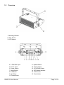
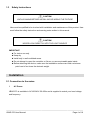
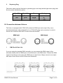
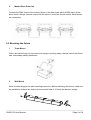
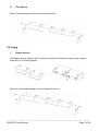
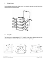
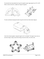
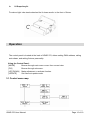
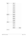
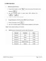
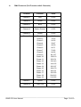
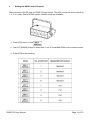
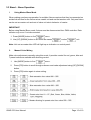
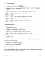
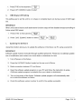
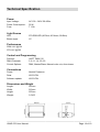
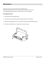
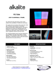
VBAR 270 User Manual Version 1.2 ____________________________________________________________________________ VBAR 270 User Manual Page 1of 19 Introduction Thank you for purchasing VBAR 270. VBAR 270 is a LED light fixture for professional use. Using the RGB color mixing technology provide up to 16.5 million colors for use in stage production and fixed installation. Its optional mounting kits offering many different ways to use this light fixture. This light fixture can be operating stand-alone or using advance control via external DMX controller. WHAT IS INCLUDED z 1 x VBAR 270 z 1 x Hanging bracket z Power Cord z User manual Carefully unpack the carton, check the contents to ensure that all parts are present, and have been received in good condition. If any parts appear damaged or missing, notify the shipper immediately and retain packing material for inspection. In the event that the fixture must be returned to the factory, it is important that the fixture be returned in the original factory box and packing. 1.1 Features z z z z z DMX 512. Standard 5 channels and full function 8 channels DMX control. Stand – alone operation: Master/Slave. Dimmable Manual color mixing and preset colors. Dimmable auto-chases with adjustable speed and fade. 19 auto chases. Special functions: Check software version. Test sequence for testing and demo purpose. Factory reset. DMX off setting. Optional bracket to make batten, blinder, light tube and multilateral shaping. ____________________________________________________________________________ VBAR 270 User Manual Page 2 of 19 1.2 Overview 1 1. Mounting Bracket 2. Gear Screw 3. LED Module 4. 5-PIN DMX Input 11. Update Button 5. Power Input 12. Power Output 6. Power Switch 13. 5-PIN DMX Output 7. Mode Button 14. LED Status Indicator 8. F/S Button 15. LCD Screen 9. Up Button 16. Fuse Holder 10. Down Button ____________________________________________________________________________ VBAR 270 User Manual Page 3 of 19 1.3 Safety Instructions CAUTION UNPLUG MAINS BEFORE INSTALLING OR WIRING THE FIXTURE User must be qualified to be involved with installation and maintenance of this product. User must follow the safety instruction and warning notes written in this manual. CAUTION NEVER LOOK DIRECTLY INTO THE LIGHT SOURCE IMPORTANT z For indoor use only z Keep dry z Install only in well ventilated areas z Do not attempt to open the controller or fixture, no user serviceable parts inside. z Before attaching the device, make sure the installation surface can hold a minimum point load of ten times the device’s weight. Installation 2.1 Connection to the mains i. AC Power VBAR 270 is available in AC100-240V 50-60Hz and is supplied to match your local voltage and frequency. ____________________________________________________________________________ VBAR 270 User Manual Page 4 of 19 ii. Replacing Plug The power cable must be fitted with a grounding-type cord cap (earthed type mains plug) that fits your power distribution system. Wire (EU) Wire (US) Pin Marking Brown Black Live L Blue White Neutral N Yellow Green GND 2.2 Connection between fixtures The fixture is equipped with 5 PIN XLR sockets for DMX input and output. Only use a shielded twisted pair cable designed for 3 or 5 PIN XLR plugs and connectors in order to connect the controller with fixture or one fixture with another. i. DMX Serial Data Link If you are using the standard DMX controller, you can connect the DMX output of the controller directly with the DMX input of the first fixture in the DMX-chain. Connect the DMX output of first fixture in the chain with DMX input of next fixture. Always connect one output with input of next fixture until all fixtures are connected. ___________________________________________________________________________ VBAR 270 User Manual Page 5 of 19 ii. Master/Slave Data Link Connect the DMX output of the master fixture in the data chain with the DMX input of first slave fixture. Always connect output with the input of next slave fixture until all slave fixtures are connected. 2.3 Mounting the fixture i. Truss Mount Fixture should be hung on truss structure using a mounting clamp. Always secure the fixture with a secondary safety attachment. ii. Wall Mount Refer to below diagram for wall mounting instruction. Before attaching the device, make sure the installation surface can hold a minimum point load of 10 times the device’s weight. ____________________________________________________________________________ VBAR 270 User Manual Page 6 of 19 iii. Floor Mount Refer to below diagram for floor mounting instruction. 2.4 Fixing i. Batten Bracket First attach fixtures together refer to instruction below, the structure design can combine maximum of 5 fixtures together. Then put on the batten stand on the end sides of fixtures. ____________________________________________________________________________ VBAR 270 User Manual Page 7 of 19 ii. Blinder Frame Refer to diagram below to install blinder frame. First install the side plate with light fixture then carefully install the hanging bracket. iii. Hinge Kit The hinge kit has 3 standard angles (60°, 72°, and 90°). It can also be adjusted manually from minimum 55° up to maximum 90°. Follow diagram below to adjust angle. ____________________________________________________________________________ VBAR 270 User Manual Page 8 of 19 For extended use simply attach two hinge kits together to gain larger angle from 110° to 180°. Refer to below instruction to attach two hinge kits together. To make multilateral shaping first attach hinge kit to the fixture follow below diagram. Link all the fixtures together using the hinge kit until it is finished. The hinge kit can also use as internal angle, simply remove the locking screw and install on the other side. ____________________________________________________________________________ VBAR 270 User Manual Page 9 of 19 iv. U-Shape Acrylic To make a light tube simply attached the U shape acrylic to the front of fixture. Operation The control panel is located at the back of VBAR 270, allows setting DMX address, calling auto-chase, and setting fixtures personality. Using the Control Panel: [MODE] Browse through main menu or esc from current view. [F/S] Browse through sub-menu. [UP] [DOWN] Make adjustment or activate function. [UPDATE] Set fixture at update mode. 3.1 Control menu map ____________________________________________________________________________ VBAR 270 User Manual Page 10 of 19 ____________________________________________________________________________ VBAR 270 User Manual Page 11 of 19 ____________________________________________________________________________ VBAR 270 User Manual Page 12 of 19 iv. DMX Protocols (Full Function with 8 Channels) Channel Function Value Channel 1 Red 0-255 Channel 2 Green 0-255 Channel 3 Blue 0-255 Channel 4 Master Dimmer 0-255 Channel 5 Strobe 0-255 Channel 6 Chase 1 Chase 2 Chase 3 0-11 12-23 24-35 Chase 4 Chase 5 Chase 6 Chase 7 Chase 8 Chase 9 Chase 10 Chase 11 Chase 12 Chase 13 Chase 14 Chase 15 Chase 16 Chase 17 Chase 18 Chase 19 36-47 48-59 60-71 72-83 84-95 96-107 108-119 120-131 132-143 144-155 156-167 168-179 180-191 192-203 204-215 216-255 Channel 7 Speed 0-255 Channel 8 Fade Time 0-255 ____________________________________________________________________________ VBAR 270 User Manual Page 13 of 19 v. Setting the DMX Control Channel There are total of 6 LED cells on VBAR 270 light fixture. The LED cell can be set to control as 1, 2, 3 or 6 cells. Total of 8 DMX control channel mode are available. 1. Press [F/S] button to find . 2. Use [UP] [DONW] button to select from 1 out of 8 available DMX control channel mode. 3. Press [F/S] to store setting. ____________________________________________________________________________ VBAR 270 User Manual Page 14 of 19 3.3 Stand – Alone Operation i. Using Master/Slave Mode When making synchronous operation for multiple fixtures requires that they be connected on a data link and one for the fixture set as master unit and rest set as slave unit. Only one fixture can be set as master unit and rest of salve unit mimic behavior of master. IMPORTANT Before using Master/Slave mode, fixtures must be disconnected from DMX controller. Data collision may occur if not disconnected. 1. Press [MODE] button to find menu. menu. 2. Use [UP] [DOWN] button to set fixture as master or slave unit. Note: Unit set as master blue LED will light up as indication on control panel. ii. Manual Color Mixing Make color adjustment manually using this mode. It provides control for red, green, blue and 7 preset colors are available with dimming control. 1. Use [MODE] button to find menu. 2. Press [F/S] button to scroll through submenu and make adjustment using [UP] [DOWN] menu. button. 3. Press [F/S] button again to store setting. ____________________________________________________________________________ VBAR 270 User Manual Page 15 of 19 ____________________________________________________________________________ VBAR 270 User Manual Page 16 of 19 ' ____________________________________________________________________________ VBAR 270 User Manual Page 17of 19 Technical Specification Power Input Voltage: Power Consumption: Fuse: AC 100 – 240V 50-60Hz 30 W T 1.0A Light Source LED: Beam angle: 270 RGB LED (90 Red, 90 Green, 90 Blue) 15° Performance 2024 LUX @ 1M 570 LUX @ 2M Control and Programming Protocol: DMX Channels: Control Options: USITT DMX 512 5, 8, 11, 14, 20, 23 DMX, Master/Slave, Manual color mix, Auto-chase Connections Power: Data: Software update: Neutrik Powercon XLR 5-PIN XLR 5-PIN Dimensions and Weight Length: Width: Height: Weight: 297mm 212mm 207mm 3.5 KG ____________________________________________________________________________ VBAR 270 User Manual Page 18 of 19 Maintenance Keep the fixture dry and only install in well-ventilated areas. Clean the fixture with a moist, lint-free cloth. Never use alcohol or solvents. To maintaining adequate cooling, clean the dust from air vent regularly. Fuse Replacement 1. Unplug mains before replacing fuse. 2. Unscrew the fuse holder using a flat head screwdriver (anti-clockwise). 3. Remove the damaged fuse from its holder and replace with exact same type fuse. 4. Insert the fuse holder back in its place then reconnect power. ____________________________________________________________________________ VBAR 270 User Manual Page 19 of 19 Alkalite LED Technology Corp. Email: [email protected] Website: www.alkalite.com