1
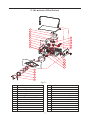
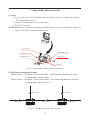
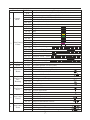
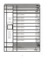
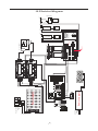
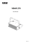
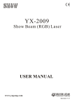
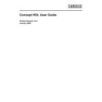
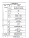
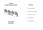
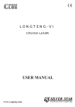
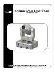
Shogun Club RGB-120
ORDERCODE 30978
1) Open the box for checking • • • • • • • • • • • • • • • • • • • • Page 1
2) Installation • • • • • • • • • • • • • • • • • • • • • • • • • • • •
Page 1
3) Attention • • • • • • • • • • • • • • • • • • • • • • • • • • • • •
Page 2
4) Warning • • • • • • • • • • • • • • • • • • • • • • • • • • • • •
Page 2
5) Structure of the fixture • • • • • • • • • • • • • • • • • • • • • • Page 3
6)Scan motor Replacement
• • • • • • • • • • • • • • • • • • • •
Page 4
7)Adjustable mirror holder• • • • • • • • • • • • • • • • • • • • • • Page 5
8)Laser diode replacement• • • • • • • • • • • • • • • • • • • • • Page 6
9) Control board instruction • • • • • • • • • • • • • • • • • • • •
10) Control board operation
• • • • • • • • • • • • • • • • • • • •
Page 7
Page 8
11)DMX512 Operate • • • • • • • • • • • • • • • • • • • • • • • • • Page 8
12) Specification • • • • • • • • • • • • • • • • • • • • • • • • • • •
Page 12
13) Maintain • • • • • • • • • • • • • • • • • • • • • • • • • • • • •
Page 12
14)Electrical diagram • • • • • • • • • • • • • • • • • • • • • • • • • Page 13
15)Trouble shooting • • • • • • • • • • • • • • • • • • • • • • • • • • Page 14
Please read over this manual before operation the light
1. Open the box for checking
In order to use this product safety and reasonable for the users, please read over
this manual carefully before use and the operation must strictly according to this
manual to avoid any damage to the product and personal safety.
Once after
received this products please take and put carefully. And check
carefully that whether the product was damaged or not during the transportation and
please check the following things were enclosed:
Laser light 1PCS
Graphics USB card 1PCS
9 pin signal line 1PCS
USB connection cable 1pcs
3 pin signal line 1pcs
User manual 1pcs
Power cable 1PCS
Install CD-ROM 1PCS
2. Installation
1. Please check the voltage whether is the same with the one showed on the
equipment or not.
2. It must ask for the technical person and set the light safety when installation. And
let the light beam at the suitable angle.
3. When install this equipment please make sure there's no flammable surfaces
(decorated things, etc) within at least 1.5M and maintain minimum distance of
0.5M from the equipment to the walls.
4. Please make sure that there's no other equipment or decorating materials
obstructed the exhaust fan and the vent-pipe.
5. Products should be install immobility.
6. In case of safety, it's very important that to connect the earth with line.
1
3. ATTENTION
Ø
Please do not open the bottom cover yourself without permission. Operate it
accord the user manual. Please call the technician in case the machine broken
down.
Ø
Do not use it under the damp and rain.
Ø
Pay attention to prevent the light from strong bump.
Ø
Prevent the dust into the product
Ø
Keep the vent-pipe well while working.
Ø
Keep the plug insert well before put into power.
Ø
Don't look the light directly to prevent make some destroy with eyes.
Ø
Don't light or extinguish frequently, otherwise the life span of the light tube will be
shortened.
Ø
In view of the special characters, after operated the light an hour the product shall
be paused about 15 minutes before be used next time.
Ø
Keep the space between light equipments and the lighted things more than one
meter.
Ø
Don't touch the product and draw the power line if you hand wet.
Ø
Don't open the cover for there have no parts the user can repair.
Ø
Don't operate the light without lamps.
Ø
If the semiconductor laser doesn't as light as before or there have some destroy
with lens or other parts, please contact the distributor in time.
Ø
When you want to retransfer the products, you'd better use the original package
to shockproof.
4. Maintain
Please use cotton stick dipped alcohol to wipe the mirrors at regular. Do
not use the wet cloth or chemical impregnant to clean the mirrors.
Please use the soft cloth to clean the surface of product.
ATTENTION: Disconnect input power before maintain.
Don't look straightly at the light sources.
NOTE: Don't seperate laser machine from laser power and repaire them by
yourself otherwise no good repair service will be supplied.i
2
5. Structure of the fixture
1
2
3
4
5
6
7
8
9
15
16
17
18
19
20
21
22
23
10
11
12
13
14
Fig5-1
No .
1
2
3
4
5
6
7
8
9
10
11
12
Description.
Power supply of green laser diode
Power supply of red laser diode
Blue laser diode
Power supply of blue laser diode
12V power supply
Power input plug
Address code PCB
Signal switch PCB
X,Y scan board
Reflect
Washer
Dustproof mirror
No.
13
14
15
16
17
18
19
20
21
22
23
3
Description.
Lens holder
shutter
Green laser diode
Power input plug
Male ILDA 25 plug
Red laser diode
Female ILDA 25 plug
Fan
Adjustable mirror stand
Scan mirror
DMX plug signal
6. Scan motor Replacement
(1) Steps:
1. Unscrew UK M6 screw and plug out male signal connector.
2. Disassemble all M4 10 screw for X,Y scanner socket so that scan motors can
be took out,put in or rotate to adjust the scan angle.
3. After adjust ,fix M4 10 screws,plug in male signal connector and then screw
UK M6 screw.
Y scan motor
UK M6 screw (with femal screw)
Signal connector(Male)
M4
M4
10 screw
X scan motor
10 screw
Fig6-1 Scan motor install diagram
(2) Optical system:
RGB mix beam be reflected out by X,Y scan mirrors.
White beam
RGB mix beam
Fig6-2 Optical System diagram
4
7. Adjustable mirror socket
(1) Steps
1. Loose setscrew of X,Y and then adjust mirror socket to suitable position by
X,Y adjustable screws.
2. Adjust Z adjustable screw at same time.
3. Fix X,Y setscrew.
NOTE:Made sure all beams through adjustable mirror socket be one point when you
adjust X,Y,Z line with adjustable screw.
Y setscrew
Z adjustable screw
Y adjustable screw
X setscrew
X adjustable screw
setscrew
Fig7-1 Adjustable mirror socket structure
(2) RGB Laser beams mix system:
Mirror socket 1:Transmit green beam,reflect red beam,and then mix out yellow
beam through mirror socket 1.
Mirror socket 2:Transmit yellow beam,reflect blue beam ,and then mix out white
beam through mirror socket 2.
Green beam
Blue beam
White beam
Red beam
Yellow beam
Mirror 2
Mirror 1
Fig7-2 RGB laser beams mix system
5
8. Laser diode replacement
Methods:
Disassemble whole laser system (include power supply,laser diode) and then
replace new one at original position.
Note:keep laser diode,power supply and cables be ompletly and don`t try to
damage,destroy or cut them so that it can be repaired (crefer fig 8-1).
Snip
4
4
Snip
3
3
Correct Method
Wong Method
6
1
4
2
5
3
Fig8-1
1
power supply of blue laser diode
4
power supply of red laser diode
2
blue laser diode
5
Green laser diode
3
red laser diode
6
power supply of green laser diode
6
9. Control board instruction
5
6
1
7 8
2
9
3
4
1
DMX IN/OUT: International standard DMX512 signal input/output
2
POWER INPUT
3
Security key switch
4
POWER ON/OFF: Power on/off
5
ILDA DB25F IN/OUT: Signal input connection port of the laser perform software that
in accordance with the ILDA standard.
6
MIC: Sound receiver
7
MIN
8
Remote Lock
9
Control Panel
Input power, with inner fuse.
Laser diode ON/OFF
MAX: Sound control
In the event of removal, laser will not emit any beam.(E.U. IEC regulation)
1. Computer software control mode
Fixture, there has a switch to select control mode - by computer or inside
program:The fixture has ILDA DB 25 connector so that it can be controlled by
computer software. In the When ILDA DB25F IN connects with QM2000 interfacial
card or USB interfacial card, the lamp will be control by software which installed in
the computer. When ILDA DB25F IN connector's connection port are free, the laser
will driver by the inside program, temporality it can control by music or DMX512
signal.
The control mode switch will check the 4th Pin (InterLock A) and the 17th Pin (
InterLock B) to adjust whether there has computer (with interfacial card) be
connected to fixture. If Pin 4 not be connected to Pin 17, it means there no interfacial
card otherwise there has and the connection port can receive all the signal of laser
7
perform software that accord with the ILDA standard, such as LD-2000 of Pangolin
company.
In the theory, all the signal of laser perform software that accord with the ILDA
Db25 standard can control the fixture. But Pin 4 and Pin 17 not be connected in some
laser perform interfacial card. You will need to sold this two pins together at Pin25
signal output connector or connect Pin4 and Pin 17of the standard Pin 25 signal cable
before use.
Note: We have tested that Pangolin Ld2000 (Qm2000 PCI interfacial card) and
our i.Top laser (USB2.0)interfacial card) can work with this fixture well. But you
will need to make changes as above mentioned when you use Mamba Black software
( Easylaser interfacial card) of MediaLaser company.
2.Inside program mode ( include DMX )
This mode will be set by address code.
10. Control board operation
1. Mode: Select working mode by pressing MODE.
2. ENTER: Press ENTER to confirm the selection .
3. UP: Press UP to add the address code .
4. DOWN: Press DOWN to decrease the address code .
5. DMX Signal: DMX512 input. LED on means there is an incoming DMX signal,
otherwise there is no MDX 512 signal or a faulty signal.
6. Work Status: LED on means the display PCB is working well.
11. DMX512 Operate
The machine can display two different patterns at the same time--24 channel version.And
the 2nd pattern can move with the main pattern-17 channel version,Also you can display one
pattern only--14channel version. The function of each channel as following(if the channnel
not mention main pattern or the 2nd pattern, it means this channel has effect for both two
patterns. Such as channel 1,4,11,12).
8
Channel
1
Control
Mode
2
Main Pattern
Colour
3
4
Main Pattern
Speed
5
Main Pattern
Rotate
6
Main Pattern
Dot+
Rotating
7
Main Pattern
move
8
Main Pattern
Extend
9
Main Pattern
Zoom
DMX Value
0-41
42~83
84~125
126~167
168~209
210~255
0~16
17~33
34~50
51~67
68~84
85~101
102~118
119~135
136~152
153~169
170~186
187~203
204~220
221~237
238~254
255
0~255
0~255
0~63
64~127
128~191
192~255
0~63
64~127
128~191
192~255
0~63
64~127
128~191
192~255
0~63
64~127
128~191
192~255
0~63
64~127
128~191
192~255
Function
Accelerated music active(Channel 2~24 no function)
Standard music active(Channel 2~24 no function)
Auto-mode(Channel 2~24 no function)
Sound accelerated manual mode
Manual(Sound active)
Manual(Auto-mode, movement auto active)
Close
Original colour
Red
Yellow
Green
Cyan
Blue
Purple
White
Single colour change
Stochastic Single colour
Rainbow colour flow
Static colour + strobe
Stochastic colour + strobe
Stochastic multi colour + strobe
Colour flow + strobe
256 patterns(0~255)
42 Class speed(0~255)/6=(0~42)
No Function
Horizontal Rotate(around Y axis)
Vertical Rotate(around X axis)
Horizontal & Vertical rotate
No Function
Rotating(around Z axis)
Dotting(only dot, no line)
Dot rotating
No Function
Horizontal Movement
Vertical Movement
Sidelong Movement
No Function
Extend in Horizontal
Extend in Vertical
Extend in Horizontal & Vertical
No Function
From small to large
from large to small
From small to large and then from large to small
9
10
Drawing speed
11
Scan speed
12
Color speed
13
Main patter
pattern Size
Twin patterns
&
position
0~255
0~2
3~255
0~255
0~2
16 Class speed(0~255)/17=(0~15) 0 no effect
Preset scan speed(Speed 50)
253 class speed(from fast to slow)
255 Class(Slow to fast)
Original Size(100%)
3~255
253 Class Size(3%~255%)
0~27
No double patterns & position(15~24 out of effect)
28~55
Pattern 1 Position B
Pattern 2 Position H
56~83
Pattern 1 Position A
Pattern 2 Position I
84~111
Pattern 1 Position D
Pattern 2 Position F
112~139
Pattern 1 Position G
Pattern 2 Position C
140~167
Pattern 1 Position H
Pattern 2 Position B
168~195
Pattern 1 Position I
Pattern 2 Position A
196~223
Pattern 1 Position F
Pattern 2 Position D
224~251
Pattern 1 Position C
Pattern 2 Position G
252~255
Pattern 1 Position E
Pattern 2 Position E
0~63
64~127
128~191
191~255
0~255
0~2
The 2nd pattern reverse with the main pattern(18~24 no effect)
The 2nd pattern rotate with the main pattern(18~24 no effect)
The 2nd pattern reverse alone(18~24 channel decide move mode)
The 2nd pattern rotate alone(18~24 channel decide move mode)
256 patterns
Original size(100%)
Postion
Reference frame
(0,0)
(0,255)
A B C
14
D E F
G H I
(0,255)
(255,255)
A (64,64)
B(128,64)
C(192,64)
D(64,128)
E(128,128)
F(64,128)
G(64,64)
H(128,64)
I(192,192)
15
the 2nd pattern
move mode
16
the 2nd pattern
17
The 2nd
pattern size
3~255
253 Class size(3%~255%)
10
0~16
17~33
34~50
51~67
68~84
85~101
102~118
119~135
The 2nd
18 pattern colour
136~152
153~169
170~186
187~203
204~220
221~237
238~254
255
0~63
19
64~127
The 2nd
Pattern Rotate 128~191
192~255
0~63
20
The 2nd
Pattern
Dot rotating
64~127
128~191
192~255
0~63
21
The 2nd
Pattern
Move
64~127
128~191
192~255
0~63
22
The 2nd
Pattern
Extend
64~127
128~191
192~255
0~63
23
Zoom
64~127
128~191
192~255
24 Drawing speed
0~255
Colse
Original color
Red
Yellow
Green
Cyan
Blue
Purple
White
Single color change
Stochastic color change--original color + a new color
Rainbow flow effecf
Original color + strobe
Stochastic color + strobe
Stochastic rainbow color + strobe
Rainbow flow + strobe
No Function
Horizontal rotate(around Y axis)
Vertical rotate(around X axis)
Horizontal & Vertical rotate
No Function
Rotate(around Z axis)
Dotting(Only dot, no line)
Dot rotating
No Function
Horizontal move
Vertical move
Sidelong move
No Function
Extend in Horizontal
Extend in Vertical
Extend in Horizontal & Vertical
No Function
From small to large
From large to small
From small to large and then to small
42 Class speed(0~255)/6=(0~42) 0 no drawing
11
12. Specification
Ø
Voltage: AC 220V~240V, 50/60Hz
Ø
Total power: 50W
Ø
Scanner: Super-speed scanner
Cooling mode: Air cooling
Ø
Scan angel : 0~ 30
Ø
DMX Channel: 24 CHS
Ø
Laser Class 3B 650nm
Ø
Laser light power: Red
Green Laser Class 3B 532nm
Blue Laser Class 3B 473nm
Control mode: Music mode, Auto-mode, DMX512
Ø
Ø
Net weight: 17 kg
Ø
Dimension: 565 x 350 x 290 mm
13. Maintain
Ø
Maintenance should be performed every 15-day period, by using a sponge which is
dipped with alcohol, rather than wet cloth or other chemical liquid, to clean the mirror.
Ø
Warning: Power must be disconnected before maintenance or repair. Do not look at the
light source directly.
ATTENTION: DISCONNECT INPUT POWER BEFORE MAINTAIN.
DON'T LOOK STRAIGHTLY AT THE LIGHT SOURCES.
NOTE: Don't seperate laser machine from laser power and repaire them by yourself
otherwise no good repair service will be supplied.
12
0V
220 ~V
INT
MIC
-15V
0V
+15V
+
~
1
DMX
2
3
4
5
6
7
8
9
G
Tg1+
2
GND
2 3
MIC
1
3
Tr1-
Tg1-
B
Tb1+
Tr2+
AC10.8V
J1A
ON
10
0V
+12V
Tb1-
Tr2-
Tg2+
Tg2Tb2+
Tb2-
TLC7528
Lm324
Lm324
Lm324
Lm324
Lm324
Lm324
Lm324
25P
Pin 25 female PC plug
Ld2000 LED
+
25P
Pin 25 male PC plug
Power LED
+
-
220VAC
IN
9
on/off
switch
Remote control
connector
1
+ TTL plug
red laser diode
1
R
Tr1+
LPC2214FBD144
TLC7528
Lm324
J5
Y scan motor
X scan motor
power supply
of red laser diode
Power supply
VR
~
FAN
VR
-+
+24V
75176
13
+
-24V
scan PCB
scan PCB
-
TTL plug
+
220VAC
IN
-
+
TTL plug
Blue aser diode
trasnsformer
+
+
Power supply
+
220 V AC
IN
7805CV
+
- ---
220v AC
IN
J5
FUSE
+
Power switch
220VAC
IN
14. Electrical diagram
Manostat power
of blue laser diode
Blue
laser diode
power supply of
green laser diode
Green laser diode
FUSE
15. Trouble shooting
Problem
No power
Causation
Replace part
Series number
Damaged Fuse
Fuse
09-00-2001-01
Damaged Pin4 switch
Pin 4 switch
Damaged power supply
No response to
music or it is
difficult beactived
by music
X,Y scanner no
strength or no
patternor scanner
shaking
No beam or beam
dim or beam can't
close, but other
functions OK
24V
08-05-0420-02
16-03-0004-00
Damaged mic
MIC
16-03-0001-00
Damaged control PCB
Control PCB
26-2A-LT211V2-00
Damaged potentiometer
Potentionmeter
04-03-0105-03
Damaged scanner
Super scan motor
15-01-2215-00
Damaged control PCB
Control PCB
26-2A-LT211V2-00
Damaged power supply
24V
Damaged scan board
Scan board
Dirty lens
Please refer to the
usermanual for
further instruction
16-03-0004-00
26-2A-FASTSCAN-00
Green laser diode
07-01-0030-08
Red laser diode
07-03-0250-01
Blue laser diode
07-02-0020-02
Damaged control PCB
Control PCB
26-2A-LT211V2-00
Control mode
setting incorrect
Please refer to the
usermanual for
further instruction
Signal switch board 4
26-2A-Sigalsw4-00
Damaged laser diode
Damaged Signal switch board
Control mode
setting incorrect
Please refer to the
usermanual for
further instruction
Damaged control PCB
Control PCB
26-2A-LT211V2-00
Damaged power supply
16-03-0004-00
24V
Can not control
Damaged address board LT-6 address code board 26-2A-LT6SW-00
other function
OK,Such as laser Damaged Signal switch board Signal switch board 4
26-2A-Sigalsw4-00
diode and fans
USB21-KT-00
USB box
USB box
Internal wires
are disconnected
USB signal cable
27-08-0005-00
L 2000 signal cable
Damaged power supply
24V
14
16-03-0019-00
Appendix: ILDADB25F PINOUTSDB 25 definens
1
X
-5 to +5V
2
Y
-5 to +5V
3
No Use
No use
4
Interlock A
Connected to Pin 17 inside the QM 2000
5
Red
0v to +2.5v
6
Green
0v to +2.5v
7
Blue
0v to +2.5v
8
No Use
No use
9
No Use
No use
10
No Use
No use
11
No Use
No use
12
Not connected
No use
13
No Use
No use
14
X
+5V to -5V
15
Y
+5V to -5V
16
No Use
No use
17
Interlock B
Connected to Pin4 inside the Qm 2000
18
Red
-2.5V to 0V
19
Green
-2.5V to 0V
20
Blue
-2.5V to 0V
21
No Use
No use
22
No Use
No use
23
No Use
No use
24
No Use
No use
25
Ground
Cable shielded
15