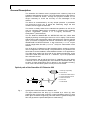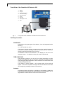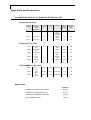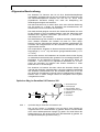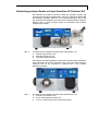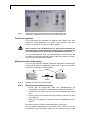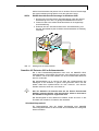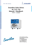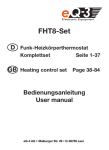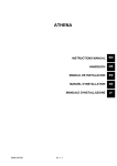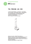
1
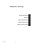
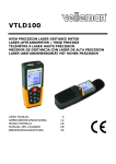
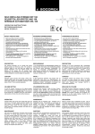
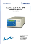
Smartline UV Detector 200
Manual / Handbuch
V 7021-1 09/2007
Wissenschaftliche Gerätebau
Dr. Ing. Herbert Knauer GmbH
Hegauer Weg 38
D - 14163 Berlin, Germany
Tel.: +49 (0)30 809 727 0
Fax.: +49 (0)30 801 50 10
E-Mail: [email protected]
Internet: www.knauer.net
1
CONTENTS
Using this Manual
Conventions in this manual
SOPs in this manual
General Description
Optical path of the Smartline UV Detector 200
Preparing the Smartline UV Detector 200 for Operation
Unpacking
Standard Delivery List
Power supply
Front View of the Smartline UV Detector 200
Foil Key Functions
Rear Panel View of the Smartline UV Detector 200
Installation of the flow cell
Capillary Connection to a HPLC System
Connecting other Instruments with the UV-Detector 200
Terminal Strip
Assembling Plug Strips
Smartline UV Detector 200 in software controlled HPLC systems
Simple Maintenance
Check of the Mercury Lamp functions
Changing the Mercury Lamp
Cleaning the Flow Cell
Changing the Measurement Path Length
Errors that can occur on the Display
Technical Data
Spare Parts and Accessories
Available Flow Cells for the Smartline UV Detector 200
Spare Parts
Warranty statement
Declaration of conformity
3
3
3
4
4
5
5
5
5
6
6
7
7
7
9
9
10
11
11
11
12
12
14
14
15
16
16
16
31
32
2
INHALT
Hinweise zum Gebrauch des Handbuchs
Konventionen in diesem Handbuch
SOP’s in diesem Handbuch
Allgemeine Beschreibung
Optischer Weg im Smartline UV Detector 200
Inbetriebnahme des Smartline UV Detector 200
Auspacken
Lieferumfang
Stromversorgung
Frontansicht des Smartline UV Detector 200
Funktion der Folientasten
Rückansicht des Smartline UV Detector 200
Installation der Messzelle
Kapillaranschluss an ein HPLC-System
Verbindung anderer Geräte mit dem Smartline UV Detector 200
Fernsteuerungsleiste
Montage der Anschlussstecker
Smartline UV Detector 200 im Softwarebetrieb
Einfache Wartung
Kontrolle der Lampenfunktion
Lampenwechsel
Messzellenreinigung
Veränderung der Messweglänge
Liste der Displaymeldungen
Technische Daten
Ersatzteile und Zubehör
Messzellen für der Smartline UV Detector 200
Ersatzteile und Zubehör, Bestellnummern
Garantiebedingungen
Konformitätserklärung
17
17
17
18
18
19
19
19
19
20
20
21
21
21
23
24
24
25
26
26
26
26
28
29
29
30
30
30
31
32
Using this Manual
3
Using this Manual
This manual refers to the Smartline UV Detector 200 Firmware Revision
3.01 or higher. It is valid for any combination with analytical flow cells
order number A 4061, A 4062, A 4063, A 4065, preparative flow cells
order number A 4066, A 4067, A 4068, A 4069 and all UZ View™ micro
flow cells in standard.
Conventions in this manual
Important Hints are marked by the marginal hand symbol.
Special warnings are indicated by the marginal warning sign and
printed in bold letters.
The marginal lamp symbol indicates helpful advice’s.
SOPs in this manual
The Standard Operating Procedures (SOP) provided with this manual
offer a convenient way of structuring complex tasks in the operation of
your Smartline UV Detector 200. They include step-by-step instructions
leading the user through all routine tasks during operation. They can be
used for documentation purposes and be copied, applied signed, and
filed in order to document the performance of the instrument.
Please operate the instrument and all accessories according to
instructions and SOPs in this manual. This ensures proper results
and longevity of your equipment.
SOP 1
SOP 2
SOP 3
SOP 4
SOP 5
SOP 6
SOP 7
SOP 8
SOP 9
Installation of the flow cell
Capillary connections.
Assembling WAGO Plug Strips
Assembling Plug Strips for an Assistant 6000
Changing the Mercury Lamp
Purging the Flow Cell
Cleaning an analytical flow cell.
Cleaning a preparative flow cell
Changing the Measurement Path Length
7
7
10
10
12
12
13
13
14
4
General Description
General Description
The Smartline UV Detector 200 is equipped with a Mercury lamp that
enables measurements at 254nm. The most intensive line of the mercury
spectrum is located at 254nm. Through this physical constant it is no
longer necessary to check the accuracy of the wavelength of the
detector.
The device is characterized by its very simple operation. It possesses
only three keys which are: to adjust the measuring range, the time
constant, and to trigger the Autozero.
The device is ideally suited for the stand-alone-operation as well as for
use in a complete system that is controlled by a Knauer HPLC software
System: ChromGate® (Version 3.1.7 or higher), EuroChrom®, or
ClarityChrom® (with interface).
The UV Detector SMARTLINE UV DETECTOR 200 can collect data
digitally by directly connecting the device to a PC or laptop. This ensures
that the device will automatically collect data without the need for manual
input. A recorder or integrator can also be connected to the UV Detector
SMARTLINE UV DETECTOR 200. A low noise level (≤ 3 x 10⁻⁵ AU) as
well as a slight base line drift (≤ 2,5 x 10⁻⁴ AU/h) is a characteristic of the
detector.
Like in all other UV-Detectors of the Smartline-Series, access to the flow
cell is configured to be user friendly. The photometer is very flexible in the
sense that it can be installed in several different areas of LC applications.
The wide range varies from flow cells for the Knauer photometer, to the
nano-HPLC-Cells with flow rates of > 100nl/min, up to the preparative
flow cells with 10 l/min.
The UV-Detector 200 as well as the Pump S 100and/or the valve drives
S 6/12/16 can be an integrative part of the Smartline Assistant 6000. Up
to three of these instruments can be placed in one Smartline housing.
Thus, even a whole HPLC system can be put into one modul.
Optical path of the Smartline UV Detector 200
1
7
6
4
3
2
1.
2.
3.
4.
5.
6.
7.
Mercury vapor lamp
Plan mirror
Interference filter 254nm
Semi transparent mirror
Reference diode
Flow cell
Photodiode
5
Fig. 1
Optical path of the Smartline UV Detector 200
The light emitted from the lamp (1) is rerouted by a mirror (2). After
passing a filter (3) the beam is split by a semi transparent mirror (4). One
beam gives a reference signal (5).The other beam is guided through the
flow cell (6) were the optical absorption is measured (7).
Preparing the Smartline UV Detector 200 for Operation
5
Preparing the Smartline UV Detector 200 for Operation
Unpacking
After unpacking, please check the device and accessories thoroughly for
any damage that may have occurred during transportation. If necessary,
contact the carrier to claim any damages.
Use the “Standard delivery list“ to check if the Smartline UV Detector 200
is complete. Please contact our service department if anything is missing
or if you need support. It is important to fill out the guarantee card and
return it to us as soon as possible.
Standard Delivery List
Smartline UV Detector 200 with Power Supply, without Flow Cell
User Manual
RS-232 Cable
Power Supply Unit
Integrator Cable
2-pin Plug Terminal Strip
Power supply
The Smartline UV Detector 200 is equipped with a universal power
supply which operates in a range of 90 to 260 Volts AC. A manual setting
of the supply voltage is, therefore, not required.
Make sure that the main power supply is properly grounded and the
correct power cable is used.
Please connect the power supply to the device. Then connect the power
cable to the power supply and the socket.
The power supply for the Smartline UV Detector 200 is not included
in the housing.
After switching it on you will see the version of the internal software on
the display (e.g. 3.01 for a few seconds).
The lamp of the device is heated up to a constant working temperature.
After approximately ten minutes you can start measurement.
6
Preparing the Smartline UV Detector 200 for Operation
Front View of the Smartline UV Detector 200
1.
2.
3.
4.
5.
6.
7.
8.
9.
1
Display
Foilpad
Knurled cell screws
Flow cell housing
Flow cell cradle
Outlet
Flow cell
Path length of cell
Inlet
2
3
4
5
10
9
Fig. 2
8
7
6
Front panel of the Smartline UV Detector 200 and flow cell
Foil Key Functions
RANGE KEY
Depending on the given signal of the detector, it can be interpreted as the
following:
1V = 1AU, 0,1AU or 0,01AU
If the button is shortly pushed, a preset value of the scale will appear. If
the button is pushed for longer that two seconds, then the value can
change by pushing the button one more time.
The different scales will be affected on the display as well as on the
integrator output . The digital recording will remain uninfluenced.
TIME CONSTANT
Using the time constant t: you can achieve a signal smoothing. It’s value
can be set to 0.05, 0.2, 1, 2, or 5 seconds. The larger this value is set the
more the signal will be smoothed. A time constant of one second fits most
of analytical purposes best.
If the button is shortly pushed (< 2s) a preset value of the scale will
appear. If the button is pushed for longer that two seconds then the value
can changed by pushing the button one more time.
Autozero
Pushing this button will perform an adjustion of the baseline. Usually the
button should be pressed shortly before starting a chromatographic run. If
digital data are transmitted this button will become blocked.
Preparing the Smartline UV Detector 200 for Operation
7
Rear Panel View of the Smartline UV Detector 200
1. Analog output
2. RS-232 Interface
3. Terminal strip Remote connections
4. 24 V – Power connector
Fig. 3
Rear panel elements of the Smartline UV Detector 200
Installation of the flow cell
The Smartline UV Detector 200 comes factory configured without a flow
cell. However, in the Chance HPLC System it is included. The device is
equipped with a "dummy" cell which does not have any optical parts.
Before operating the photometer it is necessary to install an appropriate
KNAUER flow cell.
SOP 1
Installation of the flow cell
This instruction refers to the Smartline UV Detector 200.
First, loosen the two “knurled cell screws“ and remove them.
Pull out the “flow cell housing“.
Take the dummy cell with two fingers and remove it upward.
Insert the new “Flow cell“ and make sure the engraved specifications
point towards the user. The fixing hole on the back side of the cell fits
with the corresponding metal pin of the photometer’s housing.
Finally, push the “Flow cell cradle“ with the flow cell towards the housing,
insert the two screws and tighten them manually.
Capillary Connection to a HPLC System
Before taking a measurement cell filled with fluid into operation,
please make certain that the used eluent is miscible with that one
used previously. Otherwise purge the flow cell with a medium
miscible with both the other fluids.
SOP 2
Capillary connections.
This instruction refers to the Smartline UV Detector 200.
1. Connect the outlet of the HPLC column to the inlet bushing of the
flow cell (9).
Please use DYNASEAL bushings and the shortest possible capillary
with small internal diameter in order to keep the dead volume as
small as possible.
2. Push the bushing, the clamping ring, and the sealing ring onto the
capillary. Please take care on the sequence and orientation of
fittings, see Fig. 4 „DYNASEAL Capillary connections“.
8
Preparing the Smartline UV Detector 200 for Operation
3. Push the capillary as far as possible into the flow cell input.
4. Fasten the bushing by hand.
5. Connect the flow cell outlet (6) using a capillary or teflon tube (ID >
0,5 mm) to a waste bottle.
Injection Valve
Column
Flow Cell Outlet
Flow Cell Inlet
Sealing Ring
Clamping Ring
Fig. 4
DYNASEAL Capillary connections
The capillary in a simple isocratic system is shown in the following figure.
For perspective reasons the UV Smartline UV Detector 200 is symbolized
by the flow cell and the used HPLC pump by it’s pump head.
Column
Pump Head
Sample
Waste
Flow Cell
Waste
Fig. 5
Isocratic HPLC System
Eluent
Connecting other Instruments with the UV-Detector 200
9
Connecting other Instruments with the UV-Detector 200
The UV-Detector 200 as well as the Pump S 100and/or the valve drives
S 6/12/16 can be an integrative part of the Smartline Assistant 6000. Up
to three of these instruments can be placed in one Smartline housing.
Thus, even a whole HPLC system can be put into one modul.
1
Fig. 6
2
3
Front view of the Smartline Assistant 6000 (A5003V065), with:
1
Smartline UV Detector 200,
2
Smartline Pump 100 and
3
injection valve (manual)
The GPC Sample Preparation Unit 6500 (Fig. 7) is another example. It
consists of a Smartline Pump 1000 and two versions of the Smartline
Assistant 6000. The Smartline UV Detector 200 is integrated in the Assitant
version V416.
2
1
3
Fig. 7
Front view of the Smartline Assistant 6000 (A5003V416), with:
1
Smartline UV Detector 200
2
6-Port-2-channel injection valve and
3
13-Port-1- channel switching valve for fraction collection
Terminal Strip
The terminal strip on the rear side of the Smartline UV Detector 200
serves for sending and receiving signals to or from another instrument.
Please avoid touching the electrical contacts of the socket lines.
Electrostatic discharges when touching the contacts can damage
the sensitive electronics of the device.
10
Connecting other Instruments with the UV-Detector 200
Remote Autozero
In the “stand alone“ mode a remote AUTOZERO can be carried out
when the contact between the AUTOZERO-pin and the GROUND-pin is
short circuited.
Assembling Plug Strips
The electrical connections mentioned below can be mounted as follows:
(The plug strip with two connectors is enclosed with the accessories)
2
lever
1
4
plug strip
Fig. 8
SOP 3
3
cable
Assembling WAGO Plug Strips
Assembling WAGO Plug Strips
1. Insert the rounded end of the lever latch into the square opening of
the selected connector of the plug strip.
2. Press the latch down as indicated by the arrow.
3. Insert the uninsulated end of the cable into the opening under the
catch.
4. Release the latch and remove the lever latch (1) from the plug
making sure the cable is firmly anchored in the plug strip.
If the detector is part of an Assistant 6000 all connectors are situated at
the rear of this instrument. In this case the WAGO connector is of
different shape. The mounting of the strip is verry similar..
SOP 4
Assembling Plug Strips for an Assistant 6000
1. Press down the cable clip as shown in Fig. 9 using a small srew
driver or the WAGO liner tool.
2. Insert the uninsulated end of the cable into the opening under the
latch.
3. Remove the tool from the plug. The cable is now firmly anchored in
the plug strip.
Simple Maintenance
Fig. 9
11
Mounting plug strips
Smartline UV Detector 200 in software controlled HPLC systems
The Smartline UV Detector 200 can be integrated into KNAUER-software
(ChromGate, EuroChrom or ClarityChrom) controlled HPLC systems. For
signal read out the detector has to be directly connected to the PC with a
RS232-cable.
While operating software controlled it is necessary to transmit a start
signal from the injection valve to initiate the data acquisition. This can be
done by connecting both of the injection valve cables to the autozero and
ground contact, see Fig. 3 on page 7.
The data read out is also possible with elder versions of
EuroChrom®. In this case it is to be integrated into the hardware
description as a K-200 detector.
The control signals of the WellChrom Detector K-200 are also part of the
UV-Detector 200 firmware.
Interface protocol
For data acquisition with the Smartline UV-Detector 200 and a nonKNAUER software via RS-232 you can get the interface protocol from
KNAUER upon request.
Simple Maintenance
Check of the Mercury Lamp functions
The mercury lamp in the Smartline UV Detector 200 guarantees reliable
measurements with a low noise level and a low base line drift as well as a
high sensitivity. The actual life of the mercury lamp is dependent on
various influences. A few examples of these influences are: the number
of times the lamp is ignited, the average duration of time that the lamp is
on, or the customers demands with respect to noise level and sensitivity.
The lifespan of the mercury lamp compared to the Deuterium lamp is
several times longer.
If increasing noise or recessive sensitivity is observed with the Smartline
UV Detector 200 then it is time to replace the mercury lamp.
12
Simple Maintenance
Changing the Mercury Lamp
Remove the power plug before opening the detector. Be sure to let
the lamp cool down for at least 10 minutes after switching it off.
SOP 5
Changing the Mercury Lamp
This instruction refers to the Smartline UV Detector 200.
1. Loosen the screws on the housing and remove them.
2. The lamp is soldered to the circuit board. The circuit board is on the
right side behind the mounting of the flow cell. Loosen both of the
lamp socket screws that are affixed to the circuit board.
3. Take the light circuit board out of the device.
4. Plug the lamp plug into the new circuit board.
5. Insert the new lamp circuit board and tighten all the screws.
6. Replace the housing cover and the screws.
Cleaning the Flow Cell
A noisy baseline and low sensitivity may be due to a dirty flow cell lens. In
most cases it is sufficient to purge the flow cell according to the following
SOP.
SOP 6
Purging the Flow Cell
1. Purge the flow cell using one of following solvents: sodium dodecyle
sulfate (SDS), 1m HCl, 1m NaOH, ethanol, or acetone.
2. Run the solvent through the flow cell using a syringe and leave for
approximately 5 minutes..
3. Rinse extensively with water and the blow dry using a gentle stream
of pure nitrogen.
Never dry with compressed air from a „house“ line as this will
contain microdroplets of oil that will coat the cell.
When the optics module is not in use, disconnect the flow cell and
clean out traces of salt and protein with a syringe filled with distilled
water. Before storing the flow cell inject a dilute solution (10-25%) of
ethanol or i-propanol to prevent microbial growth.
In case the flow cell purging does not provide sufficient results, all flow
cells can easily be disassembled for cleaning.
Analytical flow cells
Outer thread
Gasket
Lens
PTFE Seal
Fig. 10
Sectional view of an analytical flow cell
Simple Maintenance
SOP 7
13
Cleaning an analytical flow cell.
This instruction applies to the analytical flow cells A4061, A4062, A4063,
and A4065.
1. Unscrew the outer threads with the 3 mm hexagonal spanner
(enclosed in the flow cell’s delivery).
2. Remove the black gasket mounting of the lenses with a pair of
tweezers or by gently tapping it on a clean surface. The lens is
embedded in the gasket mounting and sealed against the flow path
with a perfluorated hydrocarbons (PTFE) seal. This seal should be
changed every time the flow cell is disassembled.
3. Take out the lenses and clean them by wiping them with a soft cloth
or an appropriate solvent in an ultrasonic bath. Be careful not to
touch the clean lens with fingers.
4. Reassemble the cell in the reverse manner, making sure that the
PTFE seal does not block the light path.
5. Tighten the outer threads carefully with the spanner to avoid
damaging the lenses.
Preparative flow cells
Screw thread
Washer
PEEK distance plate
Gasket holder
Light guide with
PTFE seal
Fig. 11
SOP 8
Sectional view of a preparative flow cell
Cleaning a preparative flow cell
This SOP applies to the following preparative flow cells: A4066, A4067,
A4068, and A4069.
1. Unlike the concave lens in the analytical flow cells, the preparative
flow cells have a rod shaped light guide.
2. Unscrew the outer thread with a hexagonal spanner.
3. Take out the stainless steel plain washer and the PEEK distance
plate (not present in A4069).
4. Take out the gasket holder with the light guide by grasping the outer
grooves with a pair of tweezers.
5. To clean the lens, push out the light guide and strip the PTFE
sealing ring
6. Reassemble the cell in the reverse order. Each time the flow cell is
disassembled use a new PTFE ring to ensure the consistency of the
flow cell.
14
Errors that can occur on the Display
Changing the Measurement Path Length
SOP 9
Changing the Measurement Path Length
This description is valid for the following preparative flow cells: A4066,
A4067 and A4068 with 1/8″ or 1/4″ connectors. The measurement path
length can be adjusted to 2; 1,25 or 0,5 mm. The measurement path
length is set to 2mm when manufactured. If desired, follow the below
steps to reduce the path length to 1,25 or 0,5 mm
1. Loosen the cap nut with a hexagonal head wrench.
2. Remove the stainless steel sealing ring and the PEEK spacer.
3. Replace the stainless steel ring and retighten the nut.
Without a spacer the light flow will be pushed deeper into the flow
cell. (0,75 mm), resulting in a reduction in the measurement path
length. To reduce the measurement path length even further to 0,5
mm use the other side of the cell in analog mode.
4. To increase the measurement path length back to 0,75 mm reinsert
the spacer.
5. Loosen the cap nut, remove the stainless steel sealing ring, and
remove the light guide mounting with a pair of tweezers.
6. Use a clean towel to push the light guide, about 1 mm, outwards in
order to increase the path length. Avoid touching the light flow with
fingers.
7. Reinsert the mounting in the cell.
8. Replace the PEEK spacer and then the stainless steel ring.
9. Carefully retighten the cap nut.
Tightening the cap nut will push the rod shaped light guide into the
right position. Inserting the spacer increases the path length to 0,75
mm. When changing the path length it is not necessary to change
the PTFE seal.
Errors that can occur on the Display
The following display symbols can appear while the Smartline UV
Detector 200 is in operation.
¯XXX: The signal value xxxx cannot be displayed on the screen due to
the fact that it is too big. Instead, choose a less sensitive measuring
range (e.g. 0.1 instead of 0.01).
_XXX: The signal value cannot be displayed on the screen due to the
fact that it is too small. Instead, choose a more sensitive measuring
range (e.g. 0.1 instead of 1).
Technical Data
15
Technical Data
Wavelength
Lamp
Lifetime of lamp
Linearity
Noise
Base line drift
Sensitivity
Time constants
Integrator Output
Auto zero
Display
Control
Weight
Dimensions
254 nm, ∆λ 20 nm
Mercury vapor lamp
approx. 6000 h
0 - 2.5 AU
3 x 10⁻⁵ AU, 1.0s;
2.5 x 10⁻⁴ AU/h, 1.0s;
6 x 10⁻⁵ AU, 1.0 s
0.05 s / 0.2 s / 1.0 s / 2.0 s / 5.0 s
-10V to +10V
remote and manual
4 digits
1 RS 232 interface,
remote socket,
analog out
1.5 kg
105 x 100 x 185 mm (W x H x D)
16
Spare Parts and Accessories
Spare Parts and Accessories
Available Flow Cells for the Smartline UV Detector 200
Analytical Flow Cells
Order No.
Cell type
Layer
Thickness
(mm);
Connector
ID channel
(mm)
Volume
(µL)
Material
Flow
Range
(mL/min)
Maximum
Pressure
(bar)
A4061
10 mm; 1/16″
1,1
10
20
300
A4042
3 mm; 1/16″
1,0
2
stainless
steel,
with heat
exchanger
stainless
steel
50
300
A4045
3 mm; 1/16″
1,0
2
PEEK
50
30
Preparative Flow Cells
A4066
0,5/1,25/2 mm
1/8″
stainless
steel
1.000
200
A4067
0,5/1,25/2 mm
1/8″
PEEK
1.000
100
A4068
0,5/1,25/2 mm
1/4″
stainless
steel
10.000
200
A4069
0,5 mm
1/16″
stainless
steel
250
200
A4095
0,5 mm
1/16″
PEEK
250
100
U-Z View™ Micro Flow Cells
A4091
8 mm
1/16″
0,150
0,140
fused silica
0,10
500
A4092
8 mm
280 µm
0,015
0,035
fused silica
0,01
500
A4093
8 mm
280 µm
0,020
0,003
fused silica
0,001
500
Spare Parts
Order No.
Mercury lamp with the circuit board
A4142
Repair kit for analytical flow cells
A1131
Repair kit for preparative flow cells
A1132
Test cell (dummy cell)
A4124
Hinweise zum Gebrauch des Handbuchs
17
Hinweise zum Gebrauch des Handbuchs
Dieses Handbuch bezieht sich auf den Smartline UV Detector 200 der
Firmwareversion 3.01 oder höher. Es gilt für alle Kombinationen mit den
analytischen Messzellen der Bestellnummern A4061, A4062, A4063,
A4065, präparative Messzellen der Bestellnummern A4066, A4067,
A4068, A4069 und alle ZU View™ Mikromesszellen in Standardausführung.
Konventionen in diesem Handbuch
Wichtige Hinweise werden in
Hinweissymbol kenntlich gemacht.
der
Marginalspalte
durch
das
Besondere Warnhinweise und Hinweise auf mögliche Probleme sind
mit dem Warnsymbol gekennzeichnet.
Ein nützlicher Tipp wird in der Marginalspalte durch das Symbol
hervorgehoben.
SOP’s in diesem Handbuch
Die Standardarbeitsanweisungen (Standard Operating Procedures,
SOP) dieses Handbuches ermöglichen die Strukturierung zusammenhängender Aufgaben beim Betrieb Ihres Smartline UV Detector 200. Sie
beinhalten schrittweise Anweisungen, die den Anwender durch alle
Aufgaben führen. Sie können gleichfalls zu Dokumentationszwecken
genutzt werden. Sie können kopiert, angewendet, unterzeichnet und
abgelegt werden, um so die Leistungsfähigkeit Ihres Gerätes zu
dokumentieren.
Bitte betreiben Sie das Gerät inklusive Zubehör gemäß der SOPs in
diesem Handbuch. Andernfalls können fehlerhafte Messergebnisse,
Beschädigungen oder gesundheitliche Beeinträchtigungen des
Anwenders eintreten, obwohl dieses Gerät außerordentlich robust
und betriebssicher ist.
SOP 1
SOP 2
SOP 3
SOP 4
SOP 5
SOP 6
SOP 7
SOP 8
SOP 9
Installation der Messzelle
Anschluss der Lösungsmittelleitung
WAGO-Anschlusssteckermontage
WAGO-Anschlusssteckermontage im Assistant 6000
Lampenwechsel
Spülen der Messzelle
Reinigung einer analytische Messzelle
Reinigung einer präparativen Messzelle
Veränderung der Messweglänge
21
21
24
25
26
26
27
28
28
18
Allgemeine Beschreibung
Allgemeine Beschreibung
Der Smartline UV Detector 200 ist mit einer Quecksiberdampflampe
ausgestattet, die Messungen bei 254 nm ermöglicht. Die intensivste Linie
des Quecksilberspektrums befindet sich bei 254 nm. Durch diese
physikalische Konstante erübrigt sich somit die Überprüfung der
Wellenlängenrichtigkeit des Detektors.
Das Gerät zeichnet sich vor allem durch seine sehr einfache Bedienung
aus. Es besitzt nur 3 Tasten: zur Einstellung des Messbereiches, der
Zeitkonstante und zum Auslösen des Autozero.
Das Gerät ist ideal geeignet sowohl für den Stand-alone-Betrieb, als auch
für den Einsatz in einem kompletten System unter der Steuerung einer
KNAUER HPLC Software: ChromGate® (ab Version 3.1.7), EuroChrom®,
oder ClarityChrom® (mit Interface).
Die Datenerfassung des Smartline UV Detector 200 kann digital erfolgen
durch direktes Verbinden des Gerätes mit ihrem PC oder Laptop.
Dadurch wird ein störungsfreies Arbeiten des Gerätes gewährleistet. Ein
Schreiber oder Integrator kann an den Smartline UV Detector 200 auch
angeschlossen werden.
Den empfindlichen Smartline UV Detector 200 kennzeichnet ein niedriger
Rauschpegel (≤ 3 x 10⁻⁵ AU) und ebenso geringe Basisliniendrift (≤ 2,5 x
10-4 AU/h).
Wie bei allen anderen UV-Detektoren der Smartline-Serie ist der Zugang
zur Messzelle anwenderfreundlich gestaltet. Eine reichhaltige Palette von
Messzellen für die KNAUER Photometer, von Nano-HPLC Zellen mit
Flussraten > 100 nL/min bis zu präparativen Messzellen mit 10 l/min,
macht den Smartline UV Detector 200 flexibel einsetzbar in vielen
Bereichen der LC Anwendungen.
Der Smartline UV Detector 200 kann neben der Smartline Pumpe 100
und/oder den Smartline Ventilantrieben S 6/12/16 integrativer Bestandteil
des Smartline Assistant 6000 sein. Der Assistant 6000 kann bis zu drei
der genannten Einzelgeräte innerhalb eines Smartlinemoduls enthalten.
Dadurch kann in einem einzigen Modul ein komplettes HPLC-System
untergebracht werden.
Optischer Weg im Smartline UV Detector 200
1
7
6
4
3
2
1.
2.
3.
4.
5.
6.
Quecksilberlampe
Umlenkspiegel
Interferenzfilter 254nm
Halbtransparenter Spiegel
Referenzdiode
Messzelle
7. Photodiode
5
Abb. 1
Optischer Weg im Smartline UV Detector 200
Das von der Lampe (1) emittierte Licht wird durch einen Spiegel (2)
umgelenkt durch ein Interferenzfilter (3) geleitet. Danach wird der Strahl
durch einen halbtransparenten Spiegel (4) geteilt. Ein Strahl liefert das
Referenzsignal (5). Der andere wird durch die Messzelle (6) geleitet, wo
die optische Absorption gemessen wird (7).
Inbetriebnahme des Smartline UV Detector 200
19
Inbetriebnahme des Smartline UV Detector 200
Auspacken
Alle KNAUER-Geräte werden ab Werk sorgfältig und sicher für den
Transport verpackt. Prüfen Sie dennoch nach dem Auspacken alle
Geräteteile und das Zubehör auf mögliche Transportschäden und
machen
Sie
ggf.
Schadenersatzansprüche
sofort
beim
Transportunternehmen geltend.
Bitte überprüfen Sie anhand der Packliste das Zubehör auf
Vollständigkeit. Sollte trotz unserer sorgfältigen Ausgangskontrollen ein
Teil fehlen, wenden Sie sich bitte an unsere Serviceabteilung.
Lieferumfang
Smartline UV Detector 200 mit Netzteil, ohne Messzelle
Handbuch
RS-232 Kabel
Netzkabel
Integratorkabel
2-polige Steckerleiste
Stromversorgung
Der Smartline UV Detector 200 hat eine universelle Stromversorgung, die
im Bereich von 90 bis 260 Volt Wechselstrom arbeitet. Eine manuelle
Einstellung entsprechend der örtlich anliegenden Spannung ist deshalb
nicht erforderlich.
Stellen Sie sicher, dass der Netzanschluss vorschriftsmäßig geerdet
ist und ein entsprechendes Netzkabel verwendet wird.
Das Netzteil des K-200 Detektors ist nicht in dessen Gehäuse integriert.
Es arbeitet ohne manuelle Umschaltung an jeder Steckdose von 90 bis
240 Volt.
Verbinden Sie das Netzteil mit dem 24V-Eingang auf der Rückseite des
Detektors. Anschließend das Netzkabel mit dem Netzanschluss.
Nach dem Einschalten erscheinen auf dem Display, siehe 1 in Abb. 2, die
Version der internen Software, wie 3.01.
Danach heizt sich die Lampe auf die konstante Arbeitstemperatur auf.
Das Gerät ist nach ca. 10 Minuten messbereit.
20
Inbetriebnahme des Smartline UV Detector 200
Frontansicht des Smartline UV Detector 200
1
1. Display
2. Folientasten
3. Rändelschrauben zur
Messzellenbefestigung
4. Messzellengehäuse
5. Messzellenhalterung
6. Messzellenausgang
7. Messzelle
8. Schichtdicke
9. Messzelleneingang
2
3
4
5
10
9
Abb. 2
8
7
6
Frontansicht des Smartline UV Detector 200 und der Messzelle
Funktion der Folientasten
Siehe Folientasten (2) in Abb. 2 „Frontansicht des K-200 UV Detektors“.
Range-Taste
Das ausgegebene Signal des Detektors (1V) kann - abhängig von der
gewählten Einstellung - folgenderweise interpretiert werden,:
1V = 1AU, 0,1AU oder 0,01AU
Wird die Taste kurz gedrückt erscheint der voreingestellte Wert der
Skalierung. Wird die Taste länger als 2s gedrückt, kann der Wert
verändert werden durch erneuertes Drücken der Taste.
Die unterschiedlichen Skalierungen wirken sich sowohl auf die Anzeige
am Display als auch auf den Intgratorausgang aus. Die digitale
Datenaufnahme bleibt davon unbeeinflusst.
Zeitkonstante
Mit Hilfe der Zeitkonstsante kann eine Signalglättung bewirkt werden. Sie
können Werte zwischen 0,05; 0,2; 1; 2 und 5 Sekunden auswählen. Je
größer der Wert der Zeitkonstante ist, um so stärker wird das Signal
geglättet. Für die meisten analytischen Zwecke ist eine Zeitkonstante von
1s am besten geeignet.
Wird die Taste kurz gedrückt (< 2s) wird der voreingestellte Wert
angezeigt. Wird die Taste länger als 2s gedrückt kann der Wert der
Skalierung verändert werden.
Autozero
Diese Taste dient zum automatischen justieren der Basislinie. Die Taste
wird in der Regel vor Beginn einer Chromatogramm-Aufzeichnung kurz
gedrückt. Werden digital Daten übertragen, ist diese Taste blockiert.
Inbetriebnahme des Smartline UV Detector 200
21
Rückansicht des Smartline UV Detector 200
1. Integratoranschluss
2. RS-232 Anschluss
3. Fernsteuerungsleiste (Autozero- bzw.
Injektionsventil-Anschluss)
4. 24 V – Spannungseingang vom
Abb. 3
Rückansicht des Smartline UV Detector 200
Installation der Messzelle
Die Lieferkonfiguration des Smartline UV Detector 200 beinhaltet keine
Messzelle. Das Gerät wird mit einer sogenannten Dummyzelle
ausgeliefert, die kein Linsensystem beinhaltet und mit der
Durchflussmessungen nicht möglich sind. Vor dem Einsatz des Smartline
UV Detector 200 muss eine aus der Palette der von KNAUER lieferbaren
Messzellen installiert werden.
SOP 1
Installation der Messzelle
1. Die Anweisung gilt für den Smartline UV Detector 200.
2. Lösen und entfernen Sie die beiden Rändelschrauben (3) von Hand.
3. Ziehen Sie das Messzellengehäuse heraus.
4. Nehmen Sie die darin befindliche Zelle oder Dummyzelle mit zwei
Fingern nach oben heraus.
5. Führen Sie die neue Messzelle (7) ein und vergewissern Sie sich,
dass die eingravierte Spezifikation zu Ihnen zeigt und der Metallstift
des Photometergehäuses in die entsprechende Fixierungsöffnung
auf der Rückseite der Zelle passt.
6. Schieben Sie nun das gesamte System an das Gehäuse, führen die
beiden Schrauben ein und ziehen diese manuell fest.
Kapillaranschluss an ein HPLC-System
Wenn Sie eine flüssigkeitsgefüllte Messzelle in Betrieb nehmen,
vergewissern Sie sich bitte, dass das benutzte Lösungsmittel mit
dem vorher verwendeten mischbar ist. Anderenfalls führen Sie bitte
eine Zwischenspülung mit einem mit beiden Flüssigkeiten
mischbaren Medium aus.
SOP 2
Anschluss der Lösungsmittelleitung
Die folgende Anweisung gilt für den Smartline UV Detector 200.
1. Verbinden Sie den Ausgang der HPLC-Säule mit der Eingangsverschraubung der Messzelle (links oben).
22
Inbetriebnahme des Smartline UV Detector 200
Verwenden Sie hierfür DYNASEAL-Verschraubungen und zur Minimierung des Totvolumens eine möglichst kurze Kapillare mit
kleinem Innendurchmesser.
2. Führen Sie die Verschraubung, den Zangenschneidring und den
Dichtring auf die Kapillare. Achten Sie auf Reihenfolge und Ausrichtung der Fittings, siehe Abb. 4 „DYNASEAL Kapillarverbindungen“.
3. Schieben Sie die Kapillare bis zum Anschlag in den Messzelleneinlass ein.
4. Ziehen Sie die Verschraubung mit den Fittings handfest an.
5. Die Ausgangsverschraubung (rechts unten) analytischer Messzellen
verbinden Sie mit Hilfe einer Kapillare oder eines Teflonschlauchs
(ID > 0,5 mm) mit der Abfallflasche.
Ventil
Säule
Messzellenauslass
Messzelleneinlass
Dichtring
Zangenschneidring
Abb. 4
DYNASEAL Kapillarverbindungen
Die Kapillarführung für ein einfaches isokratisches HPLC-System wird in
der folgenden Abbildung veranschaulicht, in der zur besseren
Übersichtlichkeit das Smartline UV Detector 200 nur als Messzelle und
die Pumpe nur als Pumpenkopf dargestellt sind.
Säule
Pumpenkopf
Probe
Abfall
Injektio nsventil
Messzelle
Abfall
Abb. 5
Isokratisches HPLC-System
Eluent
Verbindung anderer Geräte mit dem Smartline UV Detector 200
23
Verbindung anderer Geräte mit dem Smartline UV Detector 200
Der Smartline UV Detector 200 kann neben der Smartline Pumpe 100
und/oder den Smartline Ventilantrieben S 6/12/16 integrativer Bestandteil
des Smartline Assistant 6000 sein. Der Assistant 6000 kann bis zu drei
der genannten Einzelgeräte innerhalb eines Smartlinemoduls enthalten.
Dadurch kann in einem einzigen Modul ein komplettes HPLC-System
untergebracht werden.
1
Abb. 6
2
3
Frontansicht des Smartline Assistant 6000 (A5003V065), mit:
1
Smartline UV Detector 200,
2
Smartline Pump 100 und
3
manuellem Injektionsventil
Ein weiteres Anwendungsbeispiel ist das GPC-Probenreinigungssystems
6500, bestehend aus einer Smartline Pump 1000 und zwei Assistantvarianten. Hier ist der Smartline UV Detector 200 in den Assitant
6000V416 integriert.
2
1
3
Abb. 7
Frontansicht des Smartline Assistant 6000 (A5003V416), mit:
1
Smartline UV Detector 200
2
6-Port-2-Kanalinjektionsventil und
3
13-Port-1-Kanalventil für die Fraktionssammlung
24
Verbindung anderer Geräte mit dem Smartline UV Detector 200
Abb. 8
Rückansicht des Smartline Assistant 6000 (A5003V456), mit:
Smartline UV Detector 200, Pump 100 und Fraktionierventil
Fernsteuerungsleiste
An der Rückseite des Smartline UV Detector 200 befinden sich zwei
elektrische Anschlussstecker. Sie dienen dem Empfang oder dem
Senden von Signalen von oder zu anderen Geräten.
Bitte vermeiden Sie die Berührung der elektrischen Kontakte der
Anschlussleisten. Elektrostatische Entladungen bei der Berührung
der Kontakte können zur Zerstörung der Geräteelektronik führen.
Im Stand-allone-Modus kann ein ferngesteuertes Autozero über die
Fernsteuerungsleiste durchgeführt werden indem die Kontakte “Autozero”
und “Ground” kurzgeschlossen werden.
Montage der Anschlussstecker
Für die in den nächsten Kapiteln erwähnten elektrischen Verbindungen
werden die im Zubehör enthaltenen Stecker mit 2, 3 oder 4 Anschlüssen
verwendet. Sie werden wie folgt montiert.
Hebel
1
4
Anschlussstecker
3
Kabel
Abb. 9
Montage der WAGO-Anschlussstecker
SOP 3
WAGO-Anschlusssteckermontage
1. Führen Sie die abgerundete Seite des Hebelwerkzeugs am
ausgewählten Anschluss in die quadratische Öffnung des Steckers.
2. Drücken Sie den Hebel wie durch den Pfeil angezeigt nach unten
fest.
3. Führen Sie das nicht isolierte Ende des Kabels in die Öffnung unter
dem Hebel ein.
4. Öffnen Sie den Hebel und entfernen Sie das Hebelwerkzeug vom
Stecker.
Das Kabel ist jetzt im WAGO-Anschlussstecker gut verankert.
Ist der Detektor Bestandteil eines Assitant 6000, befinden sich die
Anschlüsse für alle integrierten Geräte auf der Rückseite (Abb. 8). Die
Verbindung anderer Geräte mit dem Smartline UV Detector 200
25
WAGO-Anschlussleiste hat jedoch hier ein anderes Format. Die Montage
der Anschlussleitung erfolgt jedoch nach dem gleichen Prinzip.
SOP 4
WAGO-Anschlusssteckermontage im Assistant 6000
1. Drücken Sie mit einem kleinen Schraubendreher oder dem WAGO
Keilwerkzeug wie in Abb. 10 gezeigt die Kabelklemme herunter.
2. Führen Sie das nicht isolierte Ende des Kabels in die zugehörige
Anschlussöffnung.
3. Entfernen Sie den Schraubendreher bzw. das Keilwerkzeug vom
Stecker. Das Kabel ist jetzt im WAGO-Anschlussstecker zuverlässig
verankert.
Abb. 10
Montage der Anschlussstecker
Smartline UV Detector 200 im Softwarebetrieb
Der S 200 Festwellenlängendetektor kann auch mit KNAUER HPLC
Softwarepaketen (ChromGate, EuroChrom oder ClarityChrom) ausgelesen werden. Hierzu wird der Detektor mit einem RS232-Kabel direkt mit
dem PC verbunden.
Bei Softwarebetrieb ist es sinnvoll mit Hilfe des Injektionsventils das
Startsignal an die Software zu geben. Dies geschieht indem man die
beiden Kabel des Injektionsventils mit dem Autozero- und GroundKontakt verbindet, siehe Abb. 3 auf Seite 21.
Soll der Smartline UV Detector 200 mit der älteren EuroChrom®
Software gesteuert werden, wird dies möglich, indem er als K-200 in
der Hardwareconfiguration angemeldet wird.
Die Steuersignale für den WellChrom Detektor K-200 sind auch in der
Firmware des Smartline UV Detector 200 enthalten.
Schnittstellenprotokoll:
Zur Datenaufnahme über die serielle Schnittstelle ohne KNAUER
Chromatografiesoftware ist das Protokoll der Schnittstelle auf Anfrage bei
Knauer erhältlich.
26
Einfache Wartung
Einfache Wartung
Kontrolle der Lampenfunktion
Die im Smartline UV Detector 200 eingesetzte Quecksilberdampflampe
garantiert eine Langzeitfunktionalität und zuverlässige Messungen mit
geringem Rauschen und geringer Basisliniendrift zusammen mit einer
hohen Empfindlichkeit. Die tatsächliche Nutzungsdauer der Lampe ist
von verschiedenen Einflussfaktoren abhängig, wie der Anzahl der
Lampenzündungen, der durchschnittlichen Leuchtdauer oder Ihren
Anforderungen bezüglich Rauschen und Empfindlichkeit.
Die Lebensdauer der Quecksilberdampflampe ist, verglichen mit einer
Deuteriumlampe um ein vielfaches höher.
Wenn zunehmendes Rauschen oder nachlassende Empfindlichkeit bei
der Messung mit dem Smartline UV Detector 200 beobachtet werden,
sollte die Quecksilberdampflampe durch eine neue ersetzt werden.
Lampenwechsel
Ziehen Sie den Netzstecker heraus, bevor Sie das Gerät öffnen. Bitte
lassen Sie die Lampe mindestens 10 Minuten nach dem
Ausschalten abkühlen.
SOP 5
Lampenwechsel
Die folgende Anweisung gilt für den Smartline UV Detector 200.
1. Lösen Sie die Gehäuseschrauben und heben Sie dieses ab.
2. Die Lampe ist auf der Lampenplatine aufgelötet. Letztere befindet
sich auf der rechten Seite hinter der Messzellenhalterung. Lösen Sie
die beiden Schrauben im Lampensockel mit denen die Platine
befestigt ist.
3. Nehmen Sie die Lampenplatine aus dem Gerät.
4. Stecken Sie den Lampenstecker in die neue Platine ein.
5. Setzen Sie die neue Lampenplatine ein und verschrauben Sie sie
sicher.
6. Setzen Sie die Gehäuseabdeckung wieder auf und befestigen Sie
diese mit den Schrauben.
Messzellenreinigung
Ein Rauschen der Basislinie und verringerte Empfindlichkeiten können
durch eine verschmutzte Messzelle auftreten. Häufig genügt es, die
Messzelle entsprechend der folgenden SOP zu spülen.
SOP 6
Spülen der Messzelle
1. Reinigen Sie die Messzelle mit einem der folgenden Lösemittel SDS
(Natriumdodecylsulfat), 1m HCl, 1m NaOH, Ethanol oder Aceton.
2. Spülen Sie die Zelle unter Verwendung einer Spritze und lassen Sie
das Lösemittel ca. 5. min einwirken.
3. Spülen Sie die Zelle anschließend mit viel Wasser. Anschließend
wird die Zelle im Stickstoffstrom getrocknet.
Verwenden Sie keine Pressluft zum Trocken, da diese häufig
mikroskopisch kleine Öltropfen enthält, die sich in der Zelle
niederschlagen können.
Einfache Wartung
27
Wird die Messzelle nicht verwendet, sollte sie mit 10-25%igem
Ethanol oder Isopropanol gefüllt werden.
Sollte das Spülen keinen ausreichenden Effekt erbringen, können alle
Messzellen zur Reinigung der Linsen leicht demontiert werden.
Analytische Messzellen
Gewindering
Halterung
Linse
PTFE Dichtung
Abb. 11
Schnittbild einer analytischen Messzelle
SOP 7
Reinigung einer analytische Messzelle
Diese Beschreibung gilt für die analytischen Messzellen A4061, A4062,
A4063 und A4065.
1. Lösen Sie den Gewindering mit dem 3 mm Sechskantschlüssel, der
mit der Messzelle ausgeliefert wurde.
2. Entfernen Sie die schwarze Linsenhalterung mit einer Pinzette oder
durch vorsichtiges Abtippen auf eine saubere Fläche. Die in die
Halterung eingelagerte Linse ist gegen den Fließpfad mit einer PTFE
Dichtung abgedichted. Diese Dichtung sollte bei jeder
Linsendemontage gewechselt werden.
3. Nehmen Sie die Linse heraus und reinigen Sie diese mit einem
sauberen weichen Tuch oder mit einem geeigneten Lösungsmittel in
einem Ultraschallbad. Achten Sie darauf, die saubere Linse nicht mit
den Fingern zu berühren.
4. Setzen Sie die Messzelle in umgekehrter Reihenfolge wieder
zusammen und achten Sie darauf, dass die PTFE Dichtung nicht
den Strahlengang unterbricht.
5. Ziehen sie den Gewindering sorgfältig mit dem Schlüssel fest, um
eine Beschädigung der Linse zu vermeiden.
Präparative Messzellen
Gewindering
Dichtungsring
PEEK Distanzscheibe
Dichtungshalter
Lichtführung mit
PTFE Dichtung
Abb. 12
Schnittbild einer präparativen Messzelle
Die präparativen Messzellen haben eine stabförmige Lichtführung
anstelle der konkaven Linse analytischer Zellen.
28
Einfache Wartung
SOP 8
Reinigung einer präparativen Messzelle
Diese Beschreibung gilt für die präparativen Messzellen A4066, A4067,
A4068 und A4069.
1. Lösen Sie den Gewindering mit einem Inbusschlüssel.
2. Entfernen Sie den ebenen Edelstahldichtungsring und die PEEK
Distanzscheibe (nicht vorhanden in A4069).
3. Nehmen Sie die Halterung mit der Lichtführung heraus indem Sie sie
mit einer Pinzette an den beiden äußeren Kerben erfassen.
4. Schieben Sie die Lichtführung heraus und streifen Sie zur Reinigung
der Linse die PTFE Dichtung ab.
5. Setzen Sie die Messzelle in umgekehrter Reihenfolge wieder
zusammen und verwenden Sie bei jeder Zellendemontage einen
neuen PTFE Dichtungsring, um die stabile Dichtheit der Zelle zu
sichern.
Veränderung der Messweglänge
SOP 9
Veränderung der Messweglänge
Diese Beschreibung gilt für die präparativen Messzellen A4066, A4067
und A4068 mit 1/8″ oder 1/4″ Anschlüssen. Die Messweglänge kann auf
2; 1,25 oder 0,5 mm eingestellt werden. Bei der Auslieferung ist die
Messweglänge werkseitig auf 2 mm eingestellt. Zur Reduzierung der
Weglänge auf 1,25 oder 0,5 mm verfahren Sie bitte folgendermaßen:
1. Lösen Sie den Gewindering mit einem Inbusschlüssel.
2. Entfernen Sie den ebenen Edelstahldichtungsring und die PEEK
Distanzscheibe.
3. Setzen Sie den Edelstahlring wieder ein und ziehen Sie den
Gewindering wieder sorgfältig fest.
Durch das Fehlen der Distanzscheibe wird die Lichtführung tiefer in
die Messzelle hinein geschoben (0,75 mm), was eine Verkürzung der
Messweglänge auf 1,25 mm zur Folge hat. Um eine weitere
Verkürzung auf 0,5 mm zu erreichen, verfahren Sie auf der anderen
Zellenseite in analoger Weise.
4. Um die Messweglänge in Schritten von 0,75 mm wieder zu
vergrößern, setzen Sie die Distanzscheiben wieder ein.
5. Lösen Sie den Gewindering, entfernen Sie den Edelstahldichtungsring und nehmen Sie die Halterung mit Lichtführung mit
einer Pinzette heraus.
6. Schieben Sie die Lichtführung ungefähr 1 mm nach außen, um die
Weglänge zu vergrößern. Verwenden Sie bitte ein sauberes Tuch
und vermeiden Sie die Berührung der Lichtführung mit den Fingern.
7. Fügen Sie die Halterung wieder in die Zelle ein.
8. Setzen Sie die PEEK Distanzscheibe und dann den Edelstahlring
ein.
9. Ziehen Sie den Gewindering wieder sorgfältig fest.
Beim Anziehen des Gewinderinges wird die stabförmige
Lichtführung in die richtige Position in der Zelle geschoben. Das
Einsetzen einer Distanzscheibe vergrößert so die Messweglänge um
0,75 mm. Bei einer Veränderung der Messweglänge braucht die
PTFE Dichtung nicht ausgewechselt werden.
Liste der Displaymeldungen
29
Liste der Displaymeldungen
Die folgende Liste zeigt die während des Betriebes Ihres Smartline UV
Detector 200 möglichen Displaybotschaften.
¯XXX: Der Signalwert xxxx kann nicht am Display angezeigt werden,
weil er zu groß ist. Wählen Sie einen weniger empfindlichen Messbereich
(z.B. 0.1 anstatt 0.01
_XXX: Der Signalwert ist zu klein um angezeigt zu werden. Wählen
Sie einen empfindlicheren Messbereich (z.B. 0,1 statt 1)
Technische Daten
Wellenlänge
Lampe
Lebensdauer d. Lampe
Linearität
Rauschen
Basisliniendrift
Empfindlichkeit
Zeitkonstanten
Integrator Output
Autozero
Anzeige
Steuerung
Gewicht
Abmessungen
254 nm, ∆λ 20 nm
Quecksilberdampflampe
ca.6000 h
0 – 2,5 AU
3 x 10⁻⁵ AU, 1.0s;
2,5 x 10⁻⁴ AU/h, 1.0s;
6 x 10⁻⁵ AU, 1.0 s
0,05 s/ 0,2 s / 1,0 s / 2,0 s / 5,0 s
-10V bis +10V
ferngesteuert und manuell
4 Zeichen
1 RS 232 Schnittstelle,
Fernsteuerungsanschluss, Analogeingang
1,5 kg
100 x 130x 250 mm (B x H x T)
30
Ersatzteile und Zubehör
Ersatzteile und Zubehör
Messzellen für der Smartline UV Detector 200
Analytische Durchflusszellen
Bestellnr. Schichtdicke
Zelltyp
(mm);
Anschluss
Innendurch- Volumen
messer
(µL)
(mm)
A4061
10 mm;
1/16″
1,1
10
A4042
A4045
3 mm; 1/16″
3 mm; 1/16″
1,0
1,0
2
2
Material
Edelstahl,
mit Wärmeaustauscher
Edelstahl
PEEK
Flussrate
Zul.
(mL/min) Höchstdruck
(bar)
20
300
50
50
300
30
Edelstahl
1.000
200
PEEK
1.000
100
Edelstahl
10.000
200
Edelstahl
250
200
PEEK
250
100
Präparative Durchflusszellen
A4066
A4067
A4068
A4069
A4095
0,5/1,25/2 mm
1/8″
0,5/1,25/2 mm
1/8″
0,5/1,25/2 mm
1/4″
0,5 mm
1/16″
0,5 mm
1/16″
1,7/4,3/
6,8 µl
1,7/4,3/
6,8 µl
1,7/4,3/
6,8 µl
U-Z View™ Mikro-Durchflusszellen
A4091
A4092
8 mm
1/16″
8 mm
280 µm
0,150
0,140
Quarzglas
0,10
500
0,015
0,035
Quarzglas
0,01
500
CE-Durchflusszelle
A4097
1 mm
280 µm
(Edelstahl)
Ersatzteile und Zubehör, Bestellnummern
A4142
A1131
A1132
A4124
Quecksilberdampflampe
Reparatursatz für analytische Messzellen
Reparatursatz für präparative Messzellen
Testzelle (Dummyzelle)
Garantiebedingungen
31
Guarantee statement
The guarantee period of the Smartline Smartline UV Detector 200 is 12
months beginning from the date of dispatch from Berlin. Operation
inconsistent with manufacturer's instructions or damage caused by
unauthorized service personnel are excluded from guarantee. Damage
caused by blockages and wear and tear parts such as fuses and seals
are not covered by the guarantee. Defective detectors should be sent to
the manufacturer for repair.
Wissenschaftliche Gerätebau
Dr. Ing. Herbert Knauer GmbH
Hegauer Weg 38
D-14163 Berlin
Tel: 030 – 809 727 – 0
Fax: 030 – 801 50 10
e-Mail: [email protected]
www.knauer.net
If we find a defect covered by the guarantee, repair or replacement, at
our discretion, will be carried out free of charge. Packing and transport
costs are borne by the purchaser.
Garantiebedingungen
Die werksseitige Garantie für den Smartline UV Detector 200 beträgt ein
Jahr ab Versanddatum. Unsachgemäße Bedienung des Gerätes und
Folgen einer Fremdeinwirkung sind hiervon ausgenommen. Ebenso sind
Verschleissteile wie z. B. Sicherungen, Dichtungen, Lampen und
Verstopfungsschäden sowie Verpackungs- und Versandkosten von der
Garantie ausgenommen. Bitte wenden Sie sich bei Fehlfunktionen Ihres
Smartline UV Detector 200 direkt an das Herstellerwerk:
Wissenschaftliche Gerätebau
Dr. Ing. Herbert Knauer GmbH
Hegauer Weg 38
D-14163 Berlin
Tel: 030 – 809 727 – 0
Fax: 030 – 801 50 10
e-Mail: [email protected]
www.knauer.net
Die Verpackung unserer Geräte stellt einen bestmöglichen Schutz vor
Transportschäden sicher. Prüfen Sie dennoch jede Sendung sofort auf
erkennbare Transportschäden. Bitte wenden Sie sich im Falle einer
unvollständigen oder beschädigten Sendung innerhalb von drei
Werktagen an das Herstellerwerk. Bitte unterrichten Sie auch den
Spediteur von etwaigen Transportschäden.
32
Konformitätserklärung
Declaration of conformity
Konformitätserklärung
Manufacturer’s name and address:
Herstellername und -adresse
Wissenschaftliche Gerätebau
Dr. Ing. Herbert KNAUER GmbH
Hegauer Weg 38
14163 Berlin, Germany
Smartline Smartline UV Detector 200
with different flow cells
Order Numbers, Bestellnummern: A 5055x
complies with the following requirements and product specifications:
●
●
●
Low Voltage Ordinance (73/23/EWG)
EN 61010-1 (08/2002)
Engineering Guidelines (89/392/EWG)
EMC Ordinance (89/336/EWG)
EN 6100-3-2 (10/2006)
EN 61326-1 (10/2006)
entspricht den folgenden Anforderungen und Produktspezifikationen:
●
●
●
Niederspannungverordnung (73/23/EWG)
EN 61010-1 (08/2002)
Maschinenrichtlinie (89/392/EWG)
EMV-Verordnung (89/336/EWG)
EN 6100-3-2 (10/2006)
EN 61326-1 (10/2006)
The product was tested in a typical configuration.
Das Produkt wurde in einer typischen Konfiguration geprüft.
Berlin September 24, 2007
Alexander Bünz (Managing Director)
The CE Shield is attached to the rear of the instrument.
Das Konformitätszeichen ist auf der Rückwand des Gerätes angebracht.