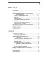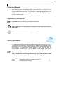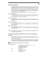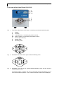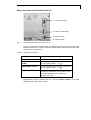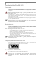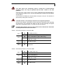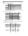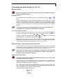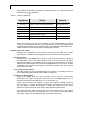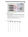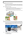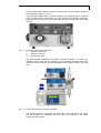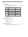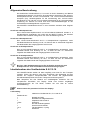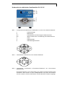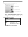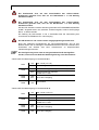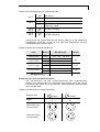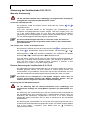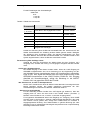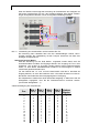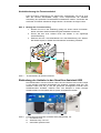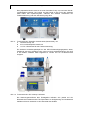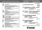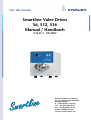
1
Smartline Valve Drives
S6, S12, S16
Manual / Handbuch
V7447-1 09/2007
Wissenschaftliche Gerätebau
Dr. Ing. Herbert Knauer GmbH
Hegauer Weg 38
D - 14163 Berlin, Germany
Tel.: +49 (0)30 809 727 0
Fax.: +49 (0)30 801 50 10
E-Mail: [email protected]
Internet: www.knauer.net
3
CONTENTS
Using this Manual .................................................................................................4
Conventions in this manual...........................................................................4
SOP´s in this manual ....................................................................................4
General Description..............................................................................................5
Preparing the Electric Valve Drives S 6/-12/-16 for Operation.............................5
Standard Delivery List ....................................................................... 5
Front view of the Valve Drives S 6/-12/-16.....................................................6
Rear view of the Valve Drives S 6/-12/-16 .....................................................7
Operating the Valve Drive S 6/-12/-16 .................................................................8
Power supply ................................................................................................8
Mounting the valve........................................................................................8
Configuring the Smartline Electric Valve Drive.............................................8
6-Port-Multi Channel Valve Switch Positions : ................................ 10
Controlling the Valve Drives S 6 /-12 /-16 ..........................................................11
Manual control ............................................................................................11
External Control of the Valve Drives S 6/-12/-16........................................11
Assembling a remote control cable.............................................................14
Valve drives S 6/12/16 as parts of the Smartline Assistant 6000..........................14
Troubleshooting ..................................................................................................16
Spare parts and accessories ..............................................................................16
Maintenance by the user ....................................................................................16
Declaration of conformity....................................................................................30
Guarantee statement..........................................................................................31
INHALT
Zur Benutzung des Handbuches ........................................................................17
Konventionen in diesem Handbuch ............................................................17
SOP´s in diesem Handbuch .......................................................................17
Allgemeine Beschreibung...................................................................................18
Inbetriebnahme des Ventilantriebs S 6/-12/-16 ..................................................18
Lieferumfang.................................................................................... 18
Vorderseite des elektrischen Ventilantriebs S 6/-12/-16...............................19
Rückseite des elektrischen Ventilantriebs S 6/-12/-16 ...............................20
Bedienung des Ventilantriebs S 6/-12/-16..........................................................21
Netzanschluss.............................................................................................21
Montage des Ventils ...................................................................................21
Konfigurierung des elektrischen Ventilantriebs ..........................................21
Schaltstellungen der 6-Port-Mehrkanalventile................................. 23
Steuerung der Ventilantriebe S 6/-12/-16...........................................................24
Manuelle Ansteuerung ................................................................................24
Externe Steuerung der Ventilantriebe S 6/-12/-16......................................24
Konfektionierung der Fernsteuerkabel........................................................27
Einbindung der Antriebe in den Smartline Assistant 6000 .................................27
Wartung durch den Anwender............................................................................29
Troubleshooting ..................................................................................................29
Ersatzteile und Zubehör .....................................................................................29
Garantiebedingungen .........................................................................................30
Konformitätserklärung ........................................................................................31
4
Using this Manual
Using this Manual
This manual refers to the Smartline Electric Valve Drives S 6, S 12, and S 16. It is
valid for any combination of the drive S 6 with the 6-port/3-channel-injection valve,
6-port/2-channel-switching valve, 7-port/1-channel- switching valve, the drive S 12
with the 13-port/1-channel- switching valve, and the drive S 16 with the 17-port/1channel- switching valve.
Conventions in this manual
Important Hints are marked by the marginal hand symbol.
Special warnings are indicated by the marginal warning sign and printed in
bold letters.
The marginal lamp symbol indicates helpful advice’s.
SOP´s in this manual
The Standard Operating Procedures (SOP) provided with this manual offer a
convenient way of structuring complex tasks for operating the Smartline Electric
Valve Drive S 6, S 12, or S 16. They include step-by-step instructions assisting the
user through all routine tasks during operation. They can be used for
documentation purposes: They can be copied, applied, signed, and filed to
document the performance of the instrument.
It is very important to follow all instructions and SOP’s in this manual in
order to operate the instrument and accessories. This ensures proper results
and longevity of your equipment.
SOP 1
SOP 2
Mounting the valve to the electric valve drive
Connecting the plug strips
8
14
General Description
5
General Description
The Smartline Electric Valve Drives S 6, S 12, and S 16 are in design and
operation for the most part identical. They are devised for automatic control of the
6-port/3-channel-injection valve, 6-port/2-channel-switching valve, 7-port/1channel-switching valve by S 6 drive, the 13-port/1-channel-switching valve by
S 12 drive, and the 17-port/1-channel-switching valve by S 16 drive respectively.
The valve drive has to be adapted to the used valve by means of a set of DIP
switches at the bottom of the drive housing.
All KNAUER valve drives can be integrated into the Smartline Assistant 6000.
Valves with 2 positions
The 6-port/3-channel-injection valve and the 6-port/2-channel-switching valve can
be switched between the LOAD and INJECT position. Switching the positions can
be done with a 60° turn forwards or backwards.
Valves with 6 positions
The 7-port/1-channel-switching valve can be switched to 6 positions. Each switch
command will result in a 60° turn, so that the 6th switch command returns to the
first position.
Valves with 12 positions
The 13-port/1-channel-switching valve can be switched to 12 positions. Each
switch command will result in a 30° turn, so that the 12th switch command returns
to the first position.
Valves with 16 positions
The 17-port/1-channel-switching valve can be switched to 16 positions. Each
switch command will result in a 22.5° turn, so that the 16th switch command returns
to the first position.
Using remote or software control valves with more than two positions can be
switched to any one directly.
Preparing the Electric Valve Drives S 6/-12/-16 for Operation
Unpacking
After unpacking, please check the device and accessories thoroughly for any
damage that may have occurred during transportation. If necessary, contact the
carrier to claim any damages.
Use the “Standard delivery list“ to check if the electric valve drive is complete.
Please contact our service department if anything is missing or if you need support.
It is important to fill out the guarantee card and return it to us as soon as possible.
Please remove the protection foil from the display!
Standard Delivery List
1
1
1
1
1 Set
1
1
1,5 m
1
Smartline Electric Valve Drives S 6, S 12, or S 16
Power supply unit 24V/50W
Power supply cable, 230V
Adapting plate 70x50 Al
Tools
RS-232 cable
WAGO Terminal Strip
Set signal conductors
User Manual
6
Preparing the Electric Valve Drives S 6/-12/-16 for Operation
Front view of the Valve Drives S 6/-12/-16
1
2.1
2.2
3
4
5
Fig. 1
Front view of the Electric Valve Drive S 16 with 17port/1channel-switching valve
1
2
2.1
2.2
3
4
5
Display
Foil keys
LOAD position, or increasing the position number
INJECT position, or decreasing the position number
Valve (7port/1channel)
Adapter plate
Mounting screw
6
2
5
3
4
Fig. 2
Schematic front view of the 7-port/1-channel-switching valve
1
6
2
5
3
4
Fig. 3
Schematic front view of the 6-port/2-channel-switching valve and the 6-port/3channel-injection valve
The actual position is shown with one or two digits on the LED display (1). For
valve drives with two positions L for LOAD and I for die INJECT will be displayed.
Preparing the Electric Valve Drives S 6/-12/-16 for Operation
7
Rear view of the Valve Drives S 6/-12/-16
1 RS-232 connector
2 Remote control strip
4 Power supply
5 Serial number
Fig. 4
Rear view of the valve drives S 6/-12/-16
Except for the power socket 4 and an additional ground connector 3, the serial
RS-232 interface 1 for external computer control and the remote control inputs and
outputs 2 can be seen here.
Table 1 Terminal connections
GROUND:
Ground connector
HOME:
Sets the valve drive to position 1
FORWARD /
LOAD:
Sets the valve drive to the LOAD position or
the next higher position i.e. 2→3
BACKWARD / INJECT:
Sets the valve drive to the INJECT position or
the next higher position i.e. 3→2
OUT:
Control output in position 1 has a lowresistance in the INJECT or in position 1 and
has a high resistance in the LOAD or in
positions 2-6 (2-16)
Depending on the DIP positions the four connectors BIN 0 to BIN 3 can be used
alternatively for binary event control.
8
Operating the Valve Drive S 6/-12/-16
Operating the Valve Drive S 6/-12/-16
Power supply
The valve drive is equipped with a universal power supply unit which operates in a
range of 90 to 260 Volts AC. A manual setting of the supply voltage is, therefore,
not required.
Make sure that the main power supply is properly grounded and the correct
power cable is used.
The power supply for the drive is not included in the housing. Please connect the
power supply to the drive (item 4 in Abb. 4). Then connect the power cable to the
power supply and the socket.
If required connect the ground connector 3 to the corresponding ground contact of
any other grounded instrument.
Wait for at least 30 seconds before restarting the drive after switching it off.
Otherwise an error message will be displayed.
Mounting the valve
The Smartline Electric Valve Drives S 6/-12/-16 have to be used in combination
with one of the KNAUER-valves. For instructions on how to operate the valves
refer to the corresponding valve manuals.
SOP 1
Mounting the valve to the electric valve drive
1.
2.
3.
4.
Fix the adapter plate with the two M4 screws at the rear side of the valve.
Set the drive on position 1 respectively LOAD.
Push the valve on the driving axle on the front side of the instrument.
Take care that the mark on the valve matches this one above the wheel. The
valve position 1 must be on top.
5. Fix the valve and adapter plate with the two mounting screws.
If the position was not set on LOAD or 1, you will get the error message E 4
when starting the drive.
Configuring the Smartline Electric Valve Drive
At the bottom of the instrument the DIP-switches 1-4 (Abb. 5) are arranged. They
are needed to adapt the drive to the actual mounted valve.
ON
1
Fig. 5
2
3
4
DIP-switches 1-4 at the drive bottom
DIP 1 adapts the two position or multi-position valve (S 6).
The valve drive S 12, exclusively used to control the 13-port/1-channel
switching valve, can only be operated with the DIP 1 switch in the ON
position!
Operating the Valve Drive S 6/-12/-16
9
The valve drive S 16, exclusively used to control the 17-port/1-channel
switching valve, can only be operated with the DIP 1 switch in the OFF
position!
Using DIP 2 the control mode is set to either FORWARD/ BACKWARD/HOME or
to the absolute position input. This will simultaneously activate the inputs BIN 0
through BIN 2.
The connector OUT/BIN3 can be used either as output or as input. The selection is
performed by setting DIP 3 and DIP 4.
The DIP-switches 3 and 4 always should be set in opposite positions.
Not all of the possible combinations of DIP positions are permitted when operating
the valve drive. If an improper DIP setting is used, an error message will appear
either when switching the drive on or when the valve is switched.
The DIP setting always has to be done with the drive switched off. Otherwise
the DIP positions will not become active.
Table 2 DIP-switch positions in valve drive S 6
DIP 1
DIP 2
ON
360° valve (7-p/1-ch)
OFF
Two position valves (6-p/2-ch and 6-p/3-ch)
ON
binary control BIN 0-2 (360° valves only)
OFF
RS-232 control/ manually/
HOME/ INJ./ LOAD
DIP 3
DIP 4
ON
OFF
OUT/ BIN 3 output
DIP 3
DIP 4
OFF
ON
not allowed
Table 3 DIP-switch positions in valve drive S 12
DIP 1
DIP 2
ON
360° valve (13-p/1-ch)
OFF
not allowed
ON
binary control BIN 0-2
OFF
RS-232 control/ manually/
HOME/ INJ./ LOAD
DIP 3
DIP 4
ON
OFF
OUT/ BIN 3 output
DIP 3
DIP 4
OFF
ON
OUT/ BIN 3 input
10
Operating the Valve Drive S 6/-12/-16
Table 4 DIP-switch positions in valve drive S 16
DIP 1
DIP 2
DIP 3
DIP 4
ON
not allowed
OFF
360° valve (17-p/1-ch)
ON
binary control BIN 0-2
OFF
RS-232 control/ manually/
HOME/ INJ./ LOAD
ON
OFF
OUT/ BIN 3 output
DIP 3
OFF
OUT/ BIN 3 input
DIP 4
ON
The data in the above tables imply that only one or two DIP combinations are
possible for any of the valves to be controlled.
Table 5 Allowed DIP combinations
Valve
Mode
6-port/2-channel
6-port/3-channel
analog
OFF OFF ON OFF
analog
ON
OFF ON OFF
binary
ON
ON
ON ON OFF
OFF ON OFF
7-port/1-channel
13-port/1-channel
17-port/1-channel
DIP position
analog
binary
Drive
analog
ON ON OFF ON
OFF OFF ON OFF
binary
OFF ON
OFF ON
1
3
DIP switch No :
2
S6
S 12
S 16
4
6-Port-Multi Channel Valve Switch Positions :
The internal port connections of the multi-channel valves are shown in the following
table.
Table 6 Port connections in multi-channel valves
(INJECT)
Operated Key
Display
(LOAD)
I
L
1
1
Connected ports
6
2
6
2-Channel valve
5
3
5
1
6
3-Channel valve
5
4
3
4
4
Connected ports
2
1
2
6
3
5
2
3
4
Controlling the Valve Drives S 6 /-12 /-16
11
Controlling the Valve Drives S 6 /-12 /-16
Manual control
In order to operate the electrical valve drives S 6/-12/-16 manually, the DIP 2
must be in the OFF position.
2 position valves
The positions LOAD and INJECT can be set by directly using the
keys.
und
In the manual mode it is still possible to integrate the valve drive into a more
complex chromatographic system. By switching the valve to the INJECT position,
the OUT connector is short circuited. This signal can start time dependent gradient
programs. The OUT connector is only active when the valve is in the INJECT
position.
To avoid unintentionally restarting the program, turn the valve back to the
LOAD position before the current program is completed.
6 , 12, and 16 position valves
Any valve position can be achieved in an increasing order by pushing the
key
as often as necessary. The steps 6→1, 12→1, or 16→1 are also considered an
increasing order. The opposite steps: 1→6, 1→12, or 1→16 are considered a
decreasing order. To decrease a step press the
key.
Similar to the two position valves, the OUT connector can be used to control other
instruments. The output is only active if the valve is in the HOME position (position
1). It is inactive if the valve is in positions 2 to 6, 2 to 12, or 2 to 16.
External Control of the Valve Drives S 6/-12/-16
The valve drive S 6/-12/-16 can be controlled with external contacts and can also
send signals to other instruments. Communication is possible via the RS-232
interface or using the additional remote control connector (Pos 2 in Fig. 4).
If more than one valve drives are integrated into the system they should be
controlled in the same control mode (RS-232 or WAGO). Specifically, if a
coupled-columns technique is required.
Control via RS-232 interface
To control any valve via the RS-232 interface the drive has to be set to the
analog mode (DIP switch 2 OFF).
The valve drives can be integrated into HPLC systems which are controlled with
software packages such as ChromGate® or EuroChrom® . Instructions can be
found in the corresponding software manuals.
The control via the serial RS-232 interface at the rear of the instrument, item 1 in
Abb. 4 on page 20, also can be performed with small selfdesigned programs which
can be integrated into non-Knauer software products.
The specifications for data transfer are:
9600 baud
8 bit
1 start-bit
1 stop-bit
12
Controlling the Valve Drives S 6 /-12 /-16
The possible commands are listed in the following table. Any command must be
confirmed using ↵ (=<ENTER>).
Table 7 Table of commands
Command
Action
Remark
1,2,3,...,6
(...,15,16,01,...)
Valve moves to the entered position
H,h
Valve moves to the HOME position (1) 360°-Valves only
L,l
Valve moves to the LOAD position
L/I -Valves only
I,i
Valve moves to the INJECT position
L/I -Valves only
V,v
Program version inquiry
P,p
Actual position inquiry
T,t
Actual valve type inquiry
360°-Valves only
Short circuit signals from the OUT connector can be used besides the RS-232
control to control other instruments. The output is active or inactive under the same
conditions as described for the manual control. If the additional inputs HOME, INJ.,
and/or LOAD are in use, the RS-232 connections have priority.
Remote control via Events
Generally the connections on the remote control strip are layed out as open
collector (OC). Therefore the right polarity of any connection has to be obeyed.
2 position valves
Using this valve, the HOME input is inactive. If the LOAD input is short circuited to
the GROUND, only the INJ. and GROUND have to be connected to the signal
sending instrument (i.e. the interface box). If no signal is sent to the INJ., the valve
will be in the LOAD position due to the LOAD GROUND short circuit. If INJ. is short
circuited as well, the valve will switch to the INJECT position. INJ. has a higher
priority than the LOAD.
6, 12, and 16 position valves
The 360° valves only can be operated either in an analog or in a binary mode. For
the corresponding DIP positions refer to table 4 on page 10.
Controlling in analog mode
Short circuit signals from the OUT connector can be used to control other
instruments. The output is only active if the valve is in the HOME position (1). It is
inactive with the valve in positions 2 to 6, 2 to 12, and 2 to 16.
Three input connectors are available. A short circuit signal to HOME moves the
valve to position 1. Similar signals to BACKW./INJ. and FORW./LOAD will move
the valve back or forward one position. To switch the valve twice in the same
direction the short circuit has to be shortly interrupted like a pulse circuit.
The most frequently used connector for the remote control strip is the Knauer
interface box IF2. This wiring is illustrated in Fig. 6. If the drive control takes place
via a pump, refer to the corresponding pump manual for the wiring.
Controlling the Valve Drives S 6 /-12 /-16
13
interface box IF2
Fig. 6
valve drive
Wiring the valve drive to the interface box IF2
Controlling in the binary mode
Switching the control into the binary mode will activate the inputs BIN 0 through
BIN 2. The output OUT is active in positions 1 through 6, however it is inactive in
the process of switching. This activity change can be used as an outgoing signal to
control other instruments.
To operate the 17-port/1-channel valve, BIN 3, also defined as an input, is
connected so that positions 9 through 16 can also be binary controlled. When
operating this valve, an output signal cannot be sent.
Every position now is binary defined as shown in the following table.
Table 8 Binary defined positions
Pos.
1
2
3
4
5
6
7
8
9
10
11
12
13
14
15
16
BIN 0
BIN 1
BIN 2
BIN 3
(23=8)
binary
result
0
1
0
1
0
1
0
1
0
1
0
1
0
1
0
1
0
0
1
1
0
0
1
1
0
0
1
1
0
0
1
1
0
0
0
0
1
1
1
1
0
0
0
0
1
1
1
1
0
0
0
0
0
0
0
0
1
1
1
1
1
1
1
1
0
1
2
3
4
5
6
7
8
9
10
11
12
13
14
15
(20=1)
(21=2)
(22=4)
14
Valve drives S 6/12/16 as parts of the Smartline Assistant 6000
Assembling a remote control cable
If the remote control is performed not using the RS-232 interface a different type of
control cable must be assembled for each application. Use the set plug strips with
connectors enclosed in the delivery to prepare your cable according the following
SOP.
SOP 2
Connecting the plug strips
Use this SOP for connecting wires to the plug strips.
1. Press down the cable clip as shown in Fehler! Verweisquelle konnte nicht
gefunden werden. using a small srew driver or the WAGO liner tool.
2. Insert the uninsulated end of the cable into the opening under the latch.
3. Remove the tool from the plug. The cable is now firmly anchored in the plug
strip.
Fig. 7
Connecting the Plug Strips
Valve drives S 6/12/16 as parts of the Smartline Assistant 6000
The valve drives S 6/12/16 as well as the UV-Detector 200 and/or the Pump S 100
can be an integrative part of the Smartline Assistant 6000. Up to three of these
instruments can be placed in one Smartline housing. Thus, even a whole HPLC
system can be put into one modul.
1
Fig. 8
2
3
Front view of the Smartline Assistant 6000 (A5003V065), with:
1
UV Detector 200,
2
Smartline Pump 100 and
3
injection valve (manual)
Valve drives S 6/12/16 as parts of the Smartline Assistant 6000
15
An electrically driven injection valve can be placed in the rear position instead of
the fractionation valve as in Fig. 9.
The preparative Modul 6100 is another example. It is equipped with a Smartline
Pump 100 and zwei two valve drives. The pump and the front valve are forming the
injection system. The second valve drive in the rear is for fractionation and solvent
recycling.
2
1
3
Fig. 9
Frontview of the Prepmodule 6100
1
Smartline Pump 100
2
Injection valve and
3
Fractionation valve
The GPC Sample Preparation Unit 6500 is another example. It consists of a
Smartline Pump 1000 and two versions of the Smartline Assistant 6000. Five
valves and one UV Detector 200 are integrated into the Assitant versions V416 and
V044.
1
Fig. 10 Front view of the GPC Cleanup Unit 6500
The control connectors of all three instruments are on the rear side of the modul.
The DIP switches for configuring the valve drive are according to the single
instruments at the bottom.
16
Troubleshooting
Troubleshooting
Error messages will be displayed in the form of „En“ (n = error code). A question
mark “?” will appear if an invalid command is entered.
Table 9 List of error codes, causes, and solutions
code
probable cause
solution
E0
valve has not switched
exchange valve sealing
E1
motor power consumption to
high
exchange valve sealing
E2
position changing to slow
exchange valve sealing
E3
DIP 3 and 4 in wrong setting
correct the settings
E4
position 1 no longer corresponds exchange valve sealing
to HOME
E5
DIP 1 and 2 in wrong setting
correct the settings
wrong binary code
correct the settings
error while reading the
EEPROM
restart the instrument
E6
In case the purposed solutions will not solve your problems, please contact our
service department.
Spare parts and accessories
Power supply cable, 230V
M1642
RS-232 cable
A0895
Set WAGO connecting rails
A1402
Set signal conductors
A1467
Maintenance by the user
The Electric Valve Drives S 6, S 12, and S 16 do not need any maintenance. In
case of problems please contact our service department.
Zur Benutzung des Handbuches
17
Zur Benutzung des Handbuches
Dieses Handbuch bezieht sich auf die elektrischen Ventilantriebe S 6, S 12 und S 16.
Es gilt für alle Kombinationen des Antriebs S 6 mit dem 6-Port/3-Kanal-Injektionsventil, dem 6-Port/2-Kanal-Schaltventil, dem 7-Port/1-Kanal-Schaltventil bzw. des
Antriebs S 12 mit dem 13-Port/1-Kanal-Schaltventil und des Antriebs S 16 mit dem
17-Port/1-Kanal-Schaltventil.
Konventionen in diesem Handbuch
Wichtige Hinweise werden in der Marginalspalte durch das Hinweissymbol
kenntlich gemacht.
Besondere Warnhinweise und Hinweise auf mögliche Probleme sind mit dem
Warnsymbol gekennzeichnet.
Ein nützlicher Tip wird in der Marginalspalte durch das Symbol hervorgehoben.
SOP´s in diesem Handbuch
Die Standardarbeitsanweisungen (Standard Operating Procedures, SOP) dieses
Handbuches ermöglichen die Strukturierung zusammenhängender Aufgaben beim
Betrieb Ihres Ventilantriebs S 6/-12/-16. Sie beinhalten schrittweise Anweisungen,
die den Anwender durch alle Aufgaben führen. Sie können gleichfalls zu
Dokumentationszwecken genutzt werden. Sie können kopiert, angewendet,
unterzeichnet und abgelegt werden, um so die Leistungsfähigkeit Ihres Gerätes zu
dokumentieren.
Bitte betreiben Sie das Gerät inklusive Zubehör gemäß der SOPs in diesem
Handbuch. Andernfalls können fehlerhafte Meßergebnisse, Beschädigungen
oder gesundheitliche Beeinträchtigungen des Anwenders eintreten, obwohl
dieses Gerät außerordentlich robust und betriebssicher ist.
SOP 1
SOP 2
Ventilmontage an den elektrischen Antrieb
Montage der Fernsteuerleitung
21
27
18
Allgemeine Beschreibung
Allgemeine Beschreibung
Die elektrischen Ventilantriebe S 6, S 12 und S 16 sind in Gestaltung und Betrieb
weitestgehend identisch. Sie sind für die automatische Ansteuerung des 6-Port/3Kanal-Injektionsventils und der 6-Port/2-Kanal- und 7-Port/1-Kanal-Schaltventile
konzipiert (S 6), beziehungsweise für die Ansteuerung des 13-Port/1-KanalSchaltventils (S 12) und des 17-Port/1-Kanal-Schaltventils (S 16). Die gegenseitige
Anpassung von Antrieb und Ventil wird durch DIP-Schalterstellungen an der
Unterseite des Antriebsgehäuses vorgenommen.
Alle KNAUER Ventilantriebe können in den Smartline Assistant 6000 integriert
sein.
Ventile mit 2 Schaltpositionen
Das 6-Port/3-Kanal-Injektionsventil und 6-Port/2-Kanal-Schaltventil werden in 2
Schaltpositionen angesteuert, der LOAD und der INJECT Position. Der Wechsel
zwischen den Positionen erfolgt durch Vor- bzw. Rückdrehung um 60°.
Ventile mit 6 Schaltpositionen
Das 7-Port/1-Kanal-Schaltventil wird in 6 Schaltpositionen angesteuert. Jeder
Schalttakt bewirkt eine Drehung um 60°, so dass mit dem 6. aufeinander folgenden
Schalttakt wieder die Ausgangsposition erreicht wird.
Ventile mit 12 Schaltpositionen
Das 13-Port/1-Kanal-Schaltventil wird in 12 Schaltpositionen angesteuert. Jeder
Schalttakt bewirkt eine Drehung um 30°, so dass mit dem 12. aufeinander
folgenden Schalttakt wieder die Ausgangsposition erreicht wird.
Ventile mit 16 Schaltpositionen
Das 17-Port/1-Kanal-Schaltventil wird in 16 Schaltpositionen angesteuert. Jeder
Schalttakt bewirkt eine Drehung um 22,5°, so dass mit dem 16. aufeinander
folgenden Schalttakt wieder die Ausgangsposition erreicht wird.
Bei Fern- oder Softwaresteuerung ist für die Ventile mit mehr als zwei
Schaltpositionen auch die direkte Positiionsansteuerung möglich.
Inbetriebnahme des Ventilantriebs S 6/-12/-16
Alle KNAUER-Geräte werden ab Werk sorgfältig und sicher für den Transport
verpackt. Prüfen Sie dennoch nach dem Auspacken alle Geräteteile und das
Zubehör auf mögliche Transportschäden und machen Sie gegebenenfalls
Schadenersatzansprüche sofort beim Transportunternehmen geltend.
Bitte überprüfen Sie das Zubehör auf Vollständigkeit. Entfernen Sie die
transparenten Schutzfolie vom Display. Sollte trotz unserer sorgfältigen
Ausgangskontrollen ein Teil fehlen, wenden Sie sich bitte an unsere
Serviceabteilung.
Please remove the protection foil from the display!
Lieferumfang
1
bestehend aus:
1
1
1
1 Satz
1
1
1,5 m
1
elektrischer Ventilantrieb S 6, S 12 oder S 16
Netzteil 24V/50W
Netzkabel mit Kaltgerätestecker
Adapterscheibe 70x50 Al
Werkzeug
RS-232 Verbindungskabel
WAGO Anschlussleiste
Flachbandkabel, 10 polig
Handbuch
Inbetriebnahme des Ventilantriebs S 6/-12/-16
19
Vorderseite des elektrischen Ventilantriebs S 6/-12/-16
1
2.1
2.2
3
4
5
Abb. 1
Vorderansicht des elektrischen Ventilantriebs S 16 mit 7-Port/1-Kanal-Schaltventil
1
2
2.1
2.2
3
4
5
Positionsanzeige
Bedientasten
LOAD Position bzw. Erhöhung der Positionsnummer
INJECT Position bzw. Verminderung der Positionsnummer
Ventil
Adapterscheibe
Imbus-Montageschrauben
6
2
5
3
4
Abb. 2
Schematische Vorderansicht 7-Port/1-Kanal-Schaltventil
1
6
2
5
3
4
Abb. 3
Schematische Vorderansicht
Injektionsventil
6-Port/2-Kanal-Schaltventil
und
6-Port/3-Kanal-
Die Positionsanzeige 1 ist als LED-Display mit 2-ziffriger Anzeige ausgelegt. Beim
Verwenden eines Ventils mit zwei Schaltpositionen wird nicht die Positionsnummer, sondern L für die LOAD Position und I für die INJECT Position angezeigt.
20
Inbetriebnahme des Ventilantriebs S 6/-12/-16
Rückseite des elektrischen Ventilantriebs S 6/-12/-16
1 RS-232 Anschluss
2 Fernsteuerungsanschluss
4 Stromversorgungsanschluss
5 Seriennummer
Abb. 4
Rückseitenansicht des elektrischen Ventilantriebs S 6/-12/-16
Außer der Stromversorgungsbuchse 4 und einem extra Masseanschluss zur
Erdung 3 finden Sie hier die serielle RS-232 Schnittstelle 1 zur externen
Computersteuerung
des
elektrischen
Ventilantriebs
und
die
Fernsteuerungseingänge und -ausgänge 2, deren Belegung die nachfolgende
Tabelle zeigt.
Tabelle 1Belegung der Fernsteuerungsanschlüsse
GROUND:
Masseanschluss
HOME:
Setzt den Ventilantrieb auf Position 1
FORWARD /
LOAD:
Setzt den Ventilantrieb auf die LOAD bzw. nächst
höhere Position z.B. 2→3
BACKWARD /
INJECT:
Setzt den Ventilantrieb auf die INJECT bzw.
nächst tiefere Position z.B. 3→2
OUT:
Steuerausgang niederohmig in Position 1 bzw.
INJECT und hochohmig in den Positionen 2-6
(2-16) bzw. LOAD
Alternativ werden die vier Anschlüsse bei entsprechender DIP-Schalterstellung als
BIN 0 bis BIN 3 für binäre Eventansteuerungen genutzt.
Bedienung des Ventilantriebs S 6/-12/-16
21
Bedienung des Ventilantriebs S 6/-12/-16
Netzanschluss
Die elektrischen Ventilantriebe S 6, S 12 und S 16 werden mit einem 24V
Gleichstrommotor betrieben. Die Stromversorgung erfolgt über ein zum
Lieferumfang gehörendes Netzteil, das für einen Spannungsbereich von 90 bis 240
Volt Wechselstrom ausgestattet ist. Ein manuelles Einstellen der anliegenden
Versorgungsspannung ist daher nicht erforderlich.
Verbinden Sie das Netzkabel mit dem Netzteil und dessen Niederspannungskabel
mit der Buchse 4 auf der Geräterückseite in Abb. 4. Der Erdungsanschluss 3 in der
Mitte unten auf der Rückplatte kann bei Bedarf mit einem Erdungskontakt oder mit
einem Erdungsanschluss anderer (geerdeter !) Geräte verbunden werden.
Warten Sie nach jedem Ausschalten eine halbe Minute vor dem Wiedereinschalten. Es erscheinen sonst Fehlermeldungen.
Montage des Ventils
Der elektrische Ventilantrieb wird in Kombination mit einem KNAUER-Ventil
betrieben. Die Handhabung des jeweiligen Ventils ist der entsprechenden
Bedienungsanleitung zu entnehmen.
SOP 1
Ventilmontage an den elektrischen Antrieb
1. Schrauben Sie die Adapterscheibe mit den beiden M4-Senkschrauben auf
die Ventilrückseite.
2. Stellen Sie den Antrieb auf die Position 1 bzw. LOAD.
3. Stecken Sie das Ventil auf die Antriebsachse des elektrischen Ventilantriebs
an der Gerätefrontseite.
4. Beachten Sie dabei, dass die Körnung auf der Ventilrückseite über
derjenigen auf der Antriebsachse liegt. Der Ventilport 1 muss nach oben
ausgerichtet sein.
5. Befestigen Sie die Adapterscheibe mit den beiden M4-Imbusschrauben am
Gehäuse.
War bei der Montage des Ventils an den Antrieb nicht Position LOAD bzw. 1
eingestellt, erscheint beim Einschalten des Gerätes die Fehlermeldung – E 4.
Konfigurierung des elektrischen Ventilantriebs
An der Geräteunterseite befinden sich die DIP-Schalter 1-4 (Abb. 5), mit denen der
Antrieb entsprechend dem montierten Ventil und dem beabsichtigten Steuermodus
konfiguriert werden muss.
ON
1
Abb. 5
2
3
4
DIP-Schalter 1-4 an der Geräteunterseite
Mit der Stellung des DIP-Schalters 1 wird bei einem S 6 der zu schaltende
Ventiltyp festgelegt, ob es sich um ein 2- oder Mehrstellungsventil handelt.
22
Bedienung des Ventilantriebs S 6/-12/-16
Der Ventilantrieb S 12, mit dem ausschließlich das 13-Port/1-KanalSchaltventil gesteuert wird, darf nur mit DIP-Schalter 1 in ON Stellung
betrieben werden!
Der Ventilantrieb S 16, mit dem ausschließlich das 17-Port/1-KanalSchaltventil gesteuert wird, darf nur mit DIP-Schalter 1 in OFF Stellung
betrieben werden!
Mit dem DIP-Schalter 2 wird die Steuerung entweder auf FORWARD/BACKWARD/
HOME eingestellt oder in die „absolute“ Positionsvorgabe, wodurch die Eingänge
BIN 0 - 2 aktiviert werden.
Die Stellung der DIP-Schalter 3 und 4 entscheidet über die Verwendung des
Anschlusses OUT/BIN3 als Ein- oder Ausgang.
Die DIP-Schalter 3 und 4 sollen immer entgegengesetzt geschaltet sein.
Nicht alle möglichen Kombinationen der DIP-Schalterstellungen sind für den
Betrieb erlaubt. Bei unzulässigen Schalterkombinationen kann es entweder beim
Einschalten des Gerätes oder beim Schaltversuch zu entsprechenden
Fehlermeldungen kommen.
Die Konfigurierung muss stets am ausgeschalteten Gerät durchgeführt
werden, sonst wird vom Gerät die Neukonfigurierung nicht übernommen.
Tabelle 2 DIP-Schalterbelegung im Ventilantrieb S 6
DIP 1
DIP 2
ON
360° Ventil (7-P/1-K)
OFF
Zweistellungsventil (6-P/2-K und 6-P/3-K)
ON
binäre Steuerung BIN 0-2 (nur 360° Ventil)
OFF
RS-232 Steuerung/ manuell/
HOME/ INJ./ LOAD
DIP 3
DIP 4
ON
OFF
OUT/ BIN 3 Ausgang
DIP 3
DIP 4
OFF
ON
nicht erlaubt
Tabelle 3 DIP-Schalterbelegung im Ventilantrieb S 12
DIP 1
DIP 2
ON
360° Ventil (13-P/1-K)
OFF
nicht erlaubt
ON
binäre Steuerung BIN 0-3
OFF
RS-232 Steuerung/ manuell/
HOME/ INJ./ LOAD
DIP 3
DIP 4
ON
OFF
OUT/ BIN 3 Ausgang
DIP 3
DIP 4
OFF
ON
OUT/ BIN 3 Eingang
Bedienung des Ventilantriebs S 6/-12/-16
23
Tabelle 4 DIP-Schalterbelegung im Ventilantrieb S 16
DIP 1
DIP 2
ON
nicht erlaubt
OFF
360° Ventil (17-P/1-K)
ON
binäre Steuerung BIN 0-3
OFF
RS-232 Steuerung/ manuell/
HOME/ INJ./ LOAD
DIP 3
DIP 4
ON
OFF
OUT/ BIN 3 Ausgang
DIP 3
DIP 4
OFF
ON
OUT/ BIN 3 Eingang
Aus den Daten der Tabellen leitet sich ab, dass für jedes der mit den elektrischen
Ventilantriebe steuerbaren Ventile nur eine oder zwei Möglichkeiten der DIPSchalterstellungen in Frage kommen.
Tabelle 5 Erlaubte DIP-Schalterkombinationen
Ventil
Modus
DIP-Stellungen
6-Port/2-Kanal
6-Port/3-Kanal
analog
OFF OFF ON OFF
7-Port/1-Kanal
analog
binär
ON
ON
OFF ON OFF
ON ON OFF
S6
13-Port/1-Kanal
analog
binär
ON
ON
OFF ON OFF
ON OFF ON
S 12
17-Port/1-Kanal
analog
binär
OFF OFF ON OFF
OFF ON OFF ON
S 16
1
DIP-Schalter Nr. :
2
Antrieb
3
4
Schaltstellungen der 6-Port-Mehrkanalventile
Das 6-Port/2-Kanal- und das 6-Port/3-Kanal-Ventil sind antriebstechnisch
identisch. Sie unterscheiden sich voneinander ausschließlich durch ihre internen
Portverbindungen. Diese sind in der folgenden Tabelle dargestellt. Weitere Details
siehe Ventilemanual.
Tabelle 6 Portverbindungen in Mehrkanalventilen
Betätigte Taste
(INJECT)
Display
(LOAD)
I
L
1
1
Verbundene Ports
6
im 2-Kanalventil
5
2
6
3
5
1
Verbundene Ports
im 3-Kanalventil
5
4
3
4
4
6
2
1
2
6
3
5
2
3
4
24
Steuerung der Ventilantriebe S 6/-12/-16
Steuerung der Ventilantriebe S 6/-12/-16
Manuelle Ansteuerung
Für den manuellen Betrieb muss unabhängig vom angesteuerten Ventiltyp der
analog-Modus eingestellt sein (DIP-Schalter 2 in OFF).
Ventile mit 2 Schaltpositionen
Die Positionen LOAD und INJECT können direkt über die Tasten
eingestellt werden.
und
Auch beim manuellen Betrieb ist die Integration des Ventilantriebs in ein
komplexes chromatographisches System möglich. Über den Ausgang OUT, der
nur in der INJECT-Stellung aktiv ist, kann durch das Umschalten auf INJECT
gleichzeitig ein Kurzschlusssignal an andere Geräte übermittelt werden, mit dem
z.B. ein zeitabhängiges Gradientenprogramm gestartet wird.
Um einen unbeabsichtigten Neustart zu vermeiden, sollte das Ventil vor
Beendigung des laufenden Programms wieder zurück in die LOAD Position
geschaltet werden.
360° Ventile mit 6, 12 oder 16 Schaltpositionen
Die einzelnen Positionen können durch Drücken der Taste
der Taste
in aufsteigender und
in abnehmender Folge erreicht werden. Die Wechsel 6→1, 12→1
beziehungsweise 16→1 sind ebenfalls aufsteigend, wie umgekehrt die direkten
Wechsel 1→6, 1→12 beziehungsweise 1→16 absteigend sind.
Auch bei diesen Ventilen können über den OUT Ausgang Kurzschlusssignale zur
Steuerung an andere Geräte gesendet werden. Der Ausgang ist jeweils aktiv,
wenn sich das Ventil in der HOME Position (=Position 1) befindet. In den
Positionen 2-6, 2-12 bzw. 2-16 ist der Ausgang inaktiv.
Externe Steuerung der Ventilantriebe S 6/-12/-16
Die elektrischen Smartline Ventilantriebe S 6/-12/-16 können sowohl durch externe
Kontakte gesteuert werden, als auch Signale an andere Geräte senden. Die
Kommunikation ist grundsätzlich sowohl über die RS-232 Schnittstelle, als auch
über den zusätzlichen Fernsteuerungsanschluss (Position 2 in Abb. 4) möglich.
Sind mehr als ein Ventilantrieb in das System integriert, sollten diese im
gleichen Steuermodus (RS-232 oder WAGO) betrieben werden. Das gilt
insbesondere für zeitgleiches Schalten in Säulenschaltungen.
Steuerung über die RS-232 Schnittstelle
Für die Steuerung über die RS-232 Schnittstelle muss unabhängig vom
angesteuerten Ventiltyp der analog-Modus eingestellt sein (DIP-Schalter 2 in
OFF).
Die Steuerung des Ventilantriebs kann über die serielle RS-232 Schnittstelle an
der Geräterückseite durch KNAUER HPLC Softwarepakete erfolgen. Über die
Einbindung des elektrischen Ventilantriebs S 6/-12/-16 in Ihr durch Software
gesteuertes System informieren Sie sich bitte im Handbuch für das zutreffende
Softwarepaket.
Die Steuerung der Ventilantriebe S 6/-12/-16 kann auch selbst programmiert und in
knauerfremde Softwareprodukte eingebunden werden. Die hierfür gültigen Befehle
sind in der Tabelle 7 aufgeführt. Jeder Befehl muss mit ↵ (=<ENTER>)
abgeschlossen werden.
Steuerung der Ventilantriebe S 6/-12/-16
25
Für die Einstellungen der Schnittstelle gilt:
9600 baud
8 bit
1 start bit
1 stop-bit
Tabelle 7 Tabelle der Kommandos
Kommando
Aktion
1,2,3,...,6
Ventil fährt in die eingegebene Position
(..,15,16,01,..)
Bemerkung
nur 360°-Ventile
H,h
Ventil fährt in die HOME-Position (Pos.1)
L,l
Ventil fährt in die LOAD-Position
nur L/I-Ventile
I,i
Ventil fährt in die INJECT-Position
nur L/I-Ventile
V,v
Ausgabe der Programmversion
P,p
Ausgabe der aktuellen Position
T,t
Ausgabe des Ventiltyps
nur 360°-Ventil
Parallel zur Steuerung über die RS-232 Schnittstelle kann der Anschluss OUT der
WAGO Anschlussleiste zur Schaltung anderer Geräte genutzt werden. Bezüglich
der Aktivierung des Ausganges gelten die gleichen Bedingungen wie beim
manuellen Betrieb. Sind auch die Anschlüsse HOME, INJ. und/oder LOAD an das
System angeschlossen, haben die RS-232 Anschlüsse Priorität.
Fernsteuerung über die Wago-Leiste
Generell gilt, dass die Anschlüsse der WAGO-Leiste als Open Collector (OC)
ausgelegt sind, weshalb die Polung von Eingängen zwingend beachtet werden
muss.
Ventile mit 2 Schaltpositionen
Der HOME Eingang ist bei diesen Ventilen inaktiv. Wenn der LOAD Eingang mit
GROUND kurzgeschlossen wird, ist zur Steuerung nur eine Verbindung von INJ.
und GROUND mit dem signalgebenden Gerät (z.B. Interface Box) erforderlich.
Liegt an INJ. kein Signal an befindet sich das Ventil aufgrund des LOAD
GROUND Kurzschlusses in der LOAD Position. Erhält der INJ. Eingang
ebenfalls ein Kurzschlusssignal, erfolgt die Schaltung in die INJECT
Position. INJ. hat gegenüber LOAD die Priorität.
360° Ventile mit 6, 12 oder 16 Schaltpositionen
Nur die 360° Ventile können über die WAGO-Leiste alternativ im analog oder binär
Modus betrieben werden. Die jeweils zugehörige Kombination der DIPSchalterstellungen entnehmen Sie bitte der Tabelle auf Seite 23.
Steuerung im analog Modus
Für die Steuerung anderer Geräte über OUT-Signale gilt wiederum, dass der
Ausgang aktiv ist, wenn sich das Ventil in der HOME Position (=Position 1)
befindet. In den Positionen 2-6, 2-12 bzw. 2-16 ist der Ausgang inaktiv.
Für eingehende Schaltbefehle stehen drei Eingänge zur Verfügung. Über HOME
wird das Ventil in die Position 1 gefahren. Während über BACKW./INJ. das Ventil
eine Position zurück gesetzt wird, erfolgt über FORW./LOAD ein Schalten in
entgegengesetzter Richtung. Zum Weiterschalten in gleicher Richtung (ab- oder
aufwärts) muss ein anliegendes Dauersignal entsprechend einer Impulsschaltung
kurzzeitig unterbrochen werden.
26
Steuerung der Ventilantriebe S 6/-12/-16
Über die WAGO-Leiste erfolgt die Anbindung der Ventilantriebe am häufigsten an
die Knauer Interface-Box IF2, bzw. den Smartline Manager 5000. Beide Verkabelungen sind praktisch identisch und in der folgenden Abbildung illustriert.
Interfacebox IF2
Abb. 6
Ventilantrieb
Verkabelung des Ventilantriebs mit der Interface Box IF2
Die Steuerung kann ebenfalls über eine der netzwerkfähigen Knauer HPLCPumpen erfolgen. Die Verkabelung mit den Pumpen entnehmen Sie bitte dem
jeweiligen Pumpenmanual.
Steuerung im binär Modus
Wird die Steuerung auf den binär Modus eingestellt, werden damit auch die
Anschlüsse BIN 0 bis BIN 2 als Eingänge aktiviert. Der Ausgang OUT ist in den
Positionen 1 bis 6 aktiv. Er ist jedoch jeweils während eines Positionswechsels
inaktiv, so dass dieser Aktivitätswechsel wiederum als Steuersignal an andere
Instrumente gesendet werden kann.
Für den Betrieb der 13- und 17-Port/1-Kanal-Ventile wird BIN 3 ebenfalls als
Eingang definiert, um auch die Positionen 9 bis 12/16 binär ansteuern zu können.
Bei diesem Ventil steht also kein Ausgangssignal zur Verfügung.
Die Sollpositionen werden über einen Binärcode festgelegt. In Klammern sind die
Wertigkeiten angegeben, über die die Positionsnummern errechnet werden.
(Summe der Wertigkeiten + 1)
Tabelle 8 Festlegung der Sollpositionen
Pos.
1
2
3
4
5
6
7
8
9
10
11
12
13
14
15
16
BIN 0
BIN 1
BIN 2
BIN 3
(23=8)
binäres
Ergebn.
0
1
0
1
0
1
0
1
0
1
0
1
0
1
0
1
0
0
1
1
0
0
1
1
0
0
1
1
0
0
1
1
0
0
0
0
1
1
1
1
0
0
0
0
1
1
1
1
0
0
0
0
0
0
0
0
1
1
1
1
1
1
1
1
0
1
2
3
4
5
6
7
8
9
10
11
12
13
14
15
(20=1)
(21=2)
(22=4)
Einbindung der Antriebe in den Smartline Assistant 6000
27
Konfektionierung der Fernsteuerkabel
Falls die externe Ansteuerung des elektrischen Ventilantriebs S 6/-12/-16 nicht
über die RS-232 Schnittstelle erfolgt, muss entsprechend der aktuellen
Anwendung ein spezielles Fernsteuerkabel konfektioniert werden. Verwenden Sie
hierfür die im Zubehör enthaltenen Wago-Stecker. Sie werden wie folgt montiert.
SOP 2
Montage der Fernsteuerleitung
1. Drücken Sie wie in der Abbildung gezeigt mit einem kleinen Schraubendreher oder dem WAGO Keilwerkzeug die Kabelklemme herunter.
2. Führen Sie das nicht isolierte Ende des Kabels in die zugehörige
Anschlussöffnung.
3. Entfernen Sie den Schraubendreher bzw. das Keilwerkzeug vom Stecker.
Das Kabel ist jetzt im WAGO-Anschlussstecker zuverlässig verankert.
Abb. 7
Zusammenbau der Anschlussstecker
Einbindung der Antriebe in den Smartline Assistant 6000
Die Ventilantrieben S 6/12/16 können neben dem UV-Detector 200 und der Pumpe
S 100 und/oder integrativer Bestandteil des Smartline Assistant 6000 sein. Der
Assistant 6000 kann bis zu drei der genannten Einzelgeräte innerhalb eines
Smartlinemoduls enthalten. Dadurch kann zum Beispiel in einem einzigen
Smartline Modul ein komplettes HPLC-System untergebracht werden.
1
Abb. 8
2
3
Frontansicht des Smartline Assistant 6000 (A5003V065), mit:
1
UV Detektor 200,
2
Smartline Pump 100 und
3
manuellem Injektionsventil
28
Einbindung der Antriebe in den Smartline Assistant 6000
Das präparative Modul 6100 ist mit einer Smartline Pump 100 und zwei Schaltventilantrieben bestückt. Die Pumpe und das Ventil an der Front des Assistant
6000 bilden das Injektionssystem, während das seitliche Schaltventil der
Fraktionssammlung und dem Solventrecycling dient.
2
1
3
Abb. 9
Frontansicht des Smartline Assistant 6000 (A5003V416), mit:
1
Smartline Pump 100
2
6-Port-2-Kanalinjektionsventil und
3
17-Port-1-Kanalventil für die Fraktionssammlung
Ein weiteres Anwendungsbeispiel ist das GPC-Probenreinigungssystems 6500,
bestehend aus einer Smartline Pump 1000 und zwei Assistantvarianten. Hier sind
in die beiden Assitants 6000 insgesamt 5 Ventile und ein UV-Detector 200
integriert.
1
Abb. 10 Frontansicht der GPC Cleanup Unit 6500
Die Steuerungsanschlüsse aller Einzelgeräte befinden sich jeweils auf der
Rückseite des Gesamtmoduls. Die Dipschalter zur Kofigurierung der Ventilantrieb
befinden sich auch weiterhin an der Unterseite des Gerätes.
Wartung durch den Anwender
29
Wartung durch den Anwender
Die Ventilantriebe sind wartungsfrei. Bei Störung wenden Sie sich bitte an den
KNAUER-Kundendienst.
Troubleshooting
Fehlermeldungen werden mit „En“ ausgegeben (n = Fehlercode). Ungültige
Eingaben werden mit „?“ beantwortet.
Tabelle 9 Liste der Fehlercodes, ihrer Ursachen und Behebung
Code
Fehler
Fehlerbehebung
E0
Das Ventil hat die Position nicht
geändert
Ventildichtung wechseln
E1
Der Motorstrom ist zu hoch
Ventildichtung wechseln
E2
Der Positionswechsel dauert zu
lange
Ventildichtung wechseln
E3
Unerlaubte Schalterstellung von
DIP 3 und 4
Schalterstellungen
korrigieren
E4
Die Position 1 stimmt nicht mehr Ventildichtung wechseln
mit der HOME-Position überein
E5
Unerlaubte Schalterstellung von
DIP 1 und 2
Schalterstellungen
korrigieren
Unerlaubter Binärcode
programmiert
Binärcode korrigieren
Fehler beim Lesen des
EEPROM
Neustart des Gerätes
E6
Sollten sich die aufgetretenen Fehler nicht in der angegebenen Weise beheben
lassen, wenden Sie sich bitte an unsere Serviceabteilung.
Ersatzteile und Zubehör
Netzkabel, 230V
M1642
RS-232 Kabel
A0895
Steckerleistensatz inkl. Hebelwerkzeug
A1402
Flachbandkabel, 10 polig
A1467
30
Guarantee statement
The guarantee period of the Smartline Electric Valve Drives S 6, S 12, and S 16
is 12 months beginning from the date of dispatch from Berlin. Operation
inconsistent with manufacturer's instructions or damage caused by
unauthorized service personnel are excluded from guarantee. Damage caused
by blockages and wear and tear parts such as fuses and seals are not covered
by the guarantee. Claims under this guarantee are valid only if the enclosed
guarantee card is returned to us at the address shown below within 14 days of
receipt of the instrument. Defective valve drives should be sent to the
manufacturer for repair.
Wissenschaftliche Gerätebau
Dr. Ing. Herbert Knauer GmbH
Hegauer Weg 38
D-14163 Berlin
Tel: 030 – 809 727 – 0
Fax: 030 – 801 50 10
e-mail: [email protected]
www.knauer.net
If we find a defect covered by the guarantee, repair or replacement, at our
discretion, will be carried out free of charge. Packing and transport costs are
borne by the purchaser.
Garantiebedingungen
Die werksseitige Garantie für die SmartlineElektrischen Ventilantriebe S 6, S 12
und S 16 beträgt ein Jahr ab Versanddatum. Unsachgemäße Bedienung des
Gerätes und Folgen einer Fremdeinwirkung sind hiervon ausgenommen.
Ebenso sind Verschleißteile wie z. B. Sicherungen, Dichtungen, Lampen und
Verstopfungsschäden sowie Verpackungs- und Versandkosten von der
Garantie ausgenommen. Die über die gesetzliche Gewährleistung
hinausgehende Garantie wird nur dann gewährt, wenn die beiliegende
Registrierkarte innerhalb von vierzehn Tagen an uns zurückgesandt wird. Bitte
wenden Sie sich bei Fehlfunktionen Ihres Elektrischen Ventilantriebs S 6, S 12
oder S 16 direkt an das Herstellerwerk:
Wissenschaftliche Gerätebau
Dr. Ing. Herbert Knauer GmbH
Hegauer Weg 38
D-14163 Berlin
Tel: 030 – 809 727 – 0
Fax: 030 – 801 50 10
e-Mail: [email protected]
www.knauer.net
Die Verpackung unserer Geräte stellt einen bestmöglichen Schutz vor
Transportschäden sicher. Prüfen Sie dennoch jede Sendung sofort auf
erkennbare Transportschäden. Bitte wenden Sie sich im Falle einer
unvollständigen oder beschädigten Sendung innerhalb von drei Werktagen an
das Herstellerwerk. Bitte unterrichten Sie auch den Spediteur von etwaigen
Transportschäden.
Declaration of conformity
31
Declaration of conformity
Konformitätserklärung
Manufacturer’s name and address:
Herstellername und -adresse
Wissenschaftliche Gerätebau
Dr. Ing. Herbert KNAUER GmbH
Hegauer Weg 38
14163 Berlin, Germany
Smartline Valve Drives S6, S12, S16
with different valves
Order Numbers, Bestellnummern: A 550xx, A551xx and A 552xx
complies with the following requirements and product specifications:
●
●
●
Low Voltage Ordinance (73/23/EWG)
EN 61010-1 (08/2002)
Engineering Guidelines (89/392/EWG)
EMC Ordinance (89/336/EWG)
EN 6100-3-2 (10/2006)
EN 61326-1 (10/2006)
entspricht den folgenden Anforderungen und Produktspezifikationen:
●
●
●
Niederspannungverordnung (73/23/EWG)
EN 61010-1 (08/2002)
Maschinenrichtlinie (89/392/EWG)
EMV-Verordnung (89/336/EWG)
EN 6100-3-2 (10/2006)
EN 61326-1 (10/2006)
The product was tested in a typical configuration.
Das Produkt wurde in einer typischen Konfiguration geprüft.
Berlin, 2007-09-24
Alexander Bünz (Managing Director)
The CE Shield is attached to the rear of the instrument.
Das Konformitätszeichen ist auf der Rückwand des Gerätes
angebracht.