1
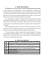
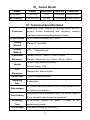
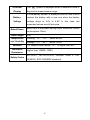
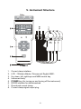
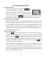
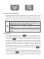
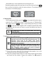
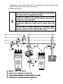
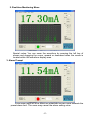
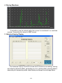
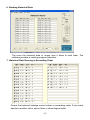
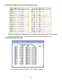
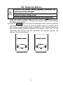
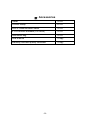
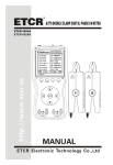
CONTENT
Warning................................................................................................. 1
I.Brief Introduction.............................................................................. 3
II.Electrical Symbol ............................................................................ 3
III.Series Model .................................................................................. 4
IV. Technical Specifications .................................................................. 4
V. Instrument Structure ......................................................................... 6
VI. Instrument Operation ...................................................................... 7
1 Turning on and off ...................................................................... 7
2. Selecting Power-saving Mode .................................................. 7
3. Date and Time Setting............................................................... 7
4. Auto Record Internal Setting ..................................................... 8
5. Data Inquiry ............................................................................... 8
6. Deleting Data............................................................................. 9
7. Leakage/current measurement................................................. 9
8. Real-time Monitoring ............................................................... 11
9. Data Download........................................................................ 11
VII. How to operate the monitor software........................................... 12
1. Home Page ............................................................................. 12
2. Real-time Monitoring Menu..................................................... 13
3. Alarm Prompt .......................................................................... 13
4. Storing Waveform.................................................................... 14
5. Historical Inquiry Display......................................................... 14
6. Reading Historical Data .......................................................... 15
7. Historical Data Queuing in Ascending Order .......................... 15
8. Historical Data Queuing in Descending Order........................ 16
9. Historical Data Storage ........................................................... 16
VIII. Replacing Battery........................................................................ 17
Ⅸ. Accessories................................................................................... 18
Warning
Thank you for buying Three-Channel Leakage/Current Monitoring
Recorder manufactured by our company. Please keep to the following
requirements in order to use the product properly:
——Read the User Manual carefully.
——Keep to the safety rules and precaution given in the manual strictly.
u
Pay special attention to safety when using this instrument in any case.
u
Observe the text and symbols attached to the front and rear panels of the
instrument.
u
Please replace the battery with a new one when the batter voltage is so low
that the LCD display is dim.
u
This instrument can not be turned off automatically. Please turn off it after
use.
u
Don not use the instrument to measure a line with a voltage higher than
600V.
u
It is forbidden to use the instrument when neither rear cover of the instrument
nor the batter cover is in place.
u
Never use the instrument when the instrument case or measuring wire is
broken and therefore any metallic part is exposed.
u
Don not place the instrument at a environment with high temperature, high
humidity, condensation and direct sunshine for a long time
u
It is necessary to maintain the instrument and clamp periodically to keep
them clean. Don not wipe the clamp by using corrosive medium or abrasive
object.
u
Avoid impact upon the current clamp, especially its mating surface
u
Please observe the correct polarity when replacing the battery. Remove the
battery from the instrument if you expect not to use the instrument for a long
time.
u
Operation, disassembly and repair of the instrument must be carried out only
by a authorized and qualified person
-1-
u
When there is an instrument fault, never use it because continual use may
result in danger. In this case, isolate the instrument immediately and
delivered to an authorized agency for dealing with it.
u
The user must follow the safety instructions preceded by “
”warning symbol
on the instrument and manual.
u
The user must follow observe the instructions preceded by “
symbol on the instrument and manual.
-2-
”danger
I.Brief Introduction
ETCR8300 series Three-Channel Current/Leakage Monitoring Recorder
is well designed and manufactured for online measurement, monitoring and
recording of Three-Channel AC leakage / current at the same time. It is composed
of a tester, monitoring software, current clamp and communication cable, etc. This
instrument has been widely applied the 380/220 Power system. It can provide a
safety and convenience measurement with accurate results.
The instrument has a large LCD display with blue background and a large
storage space. 3900 sets of data can be stored in the instrument. Three- channel
current value can be display on the screen. System clock can be set. In addition,
the instrument can automatically store data at an interval, which is adjustable from
1 to 99 min.
Monitoring software provides online and real-time monitoring and historical
data inquiry. With the software developed by our technical department, the users
can read, inquire, store, generate and print a fitting curve and report.
The current clamp is made of a special alloy, adopts the latest CT technique
and magnetic shielding technique and is not almost interfered by external
magnetic field. This ensures high accuracy, high stability and high reliability of the
values which are measured continuously.
II.Electrical Symbol
Extremely dangerous!The operators must keep to the safety
rules strictly, otherwise, electric shock will result in death or injury.
Dangerous!The operators must keep to the safety rules strictly,
otherwise, electric shock will result in will result in death or injury.
Warning!The operators must keep to the safety rules strictly,
otherwise, personal injury or equipment damage will occur..
Double insulation
Alternating current (AC)
Direct current (DC)
-3-
III.Series Model
Model
ETCR8300
ETCR8300B
Range
Resolution
Accuracy
Clamp size
0.0A-500A
0.1A
±2%±5dgt
35mm×40mm
0.00mA-20A
0.01mA
±2%±5dgt
25mm×30mm
IV. Technical Specifications
Measuring Three- channel AC leakage current and AC
Functions
current, on-line monitoring and recording, locating
insulation faults and repairing electrical lines.
Power source
Testing
Method
Display
Method
DC6V, alkaline battery LR6 1.5V×4
Clamp CT, true RMS
LCD:128dots×64dots
Instrument
Tester(L×W×H): 75mm ×170mm ×30mm
Dimension
Current clamp(L×W×H): 170mm ×70mm ×38mm
Weight
LCD
Dimension
Shield Type
Sampling
Rate
Data storage
Time Setting
Recording
Time
Line Voltage
Tester: 240g (battery included)
Current clamp: 170g
Display field: 44mm×27mm
Type B: Double shielding
2 samples/s
3900 sets (data loss does not occur after power failure
or replacing the battery)
Recording internal adjustable from 1 to 99 min, If set to
0 min, the auto-store function is turned off
Continuously operate for about 10 days at the
power-saving mode
Line with a voltage up to AC600V
-4-
Overflow
Display
The “OL” symbol is displayed when a measured value is
beyond the measurement range
A Low-Battery symbol is displayed and the user should
Battery.
replace the battery with a new one when the battery
Voltage
voltage drops to 4.6V to 4.8V. In this case, the
measured values are still accurate.
Rated Power
about 5mA at the power-saving mode, maximum current
consumption: 20mA
Lead Length
2m
Temperature
Working: -10℃~40℃;below 80%rh
and Humidity
Storage: -10℃~60℃;below 70%rh
Variation
Insulation
Resistance
Safety Codes
1% variation when below -10℃ or higher than 40℃
Higher than 100MΩ, 1000V
IEC1010-1, IEC1010-2-032, Pollution Class 2, CAT
Ⅲ(600V), IEC61326(EMC standard)
-5-
V. Instrument Structure
1. Current clamp interface
2. LCD(128dots×64dots, Chinese and English MMI)
3. Up, down, left, right keys and MEM control key
4. Instrument body
5. POWER key (for turning on and turning off the instrument)
6. RS232 interface for data download
7. Round-end current clamp
8. Current clamp signal output plug
-6-
VI. Instrument Operation
1 Turning on and off
Turn on the instrument by pressing the POWER key.
The LCD will light up. The display on the LCD is as
shown in the left figure. If the LCD display is dim, the
battery voltage may be low. If so, replace the battery
with a new one. Press the POWER key again to turn off the instrument. This
instrument can not be turned off automatically. Please turn off it after use.
2. Selecting Power-saving Mode
Press the DOWN arrow key at the measurement status to turn off the LCD
back-light and enter the power-saving mode. Press the UP arrow key to turn
on the backlight. The power consumption at the power-saving mode is only
20 percent of the one at the common mode (the backlight is turned on). It is
recommended that the power-saving mode be adopted for long-time online
measurement and recording.
3. Date and Time Setting
Press the MEM key at the measurement state to access the function menu,
press the UP or DOWN arrow keys to move the cursor to the Time Setting
item, and press the MEM key again to enter the date& time setting mode. At
the date& time setting mode, press the UP/DOWN arrow keys to change
values, press the LEFT or RIGHT keys to move the cursor, press MEM key
to “confirm” or “cancel” the setting.
After the recording interval has been set, return to the measurement state.
The instrument will automatically store the measured values at the set
interval. The instrument can store up to 3900 data sets. If the memory is full,
FULL will be displayed on the LCD. The instrument can store new data only
after some of stored data is deleted.
-7-
4. Auto Record Internal Setting
Under the test mode, press UP and Down array to set the internal time for
automatically record. The internal time can be set from 1 to 99 min. 00 min
means auto record function is closed, which is default setting after each boot
up.
The instrument doesn’t have automatic clock function. The
date and time will reset to the default value (08.08 AM, Aug
8, 2008) each time the instrument is turned on.
Press the MEM key to “Cancel” or maintain the previous
setting.
The storage interval is defaulted to “00” min each time the
instrument is turned on, that is to say, no measured value is
stored.
5. Data Inquiry
At the measurement state, press the MEM key to access the function menu,
press the UP or DOWN arrow keys to move the cursor to “Data Inquiry” item,
and press the MEM key to enter the inquiry submenu. Inside the inquiry
submenu, the first left line display the current page number and total pages,
the third line displays three sets of recorded values, and the right side
displays the page number increment. It is allowed to rapidly navigate to the
desired page number. Press the UP or DOWN arrow keys to move the
cursor and select the page number increment and then press the MEM key
to confirm the selection.
Press the LEFT and RIGHT arrow keys under the inquiry submenu to move
the cursor. Press the MEM key with the cursor located at certain data set to
display the detailed information about this data set, including the set number
-8-
/stored data sets, current amplitude and recording time, etc.
Generally speaking, press the arrow keys to move the cursor and press MEM
key to confirm the selection under the inquiry submenu. The relevant display
is as shown in the following figure:
6. Deleting Data
At the measurement state, press the MEM key to access the function menu,
press the UP or DOWN arrow keys to move the cursor to “Deleting Data”
item, When press the MEM key again, a data deleting tips will pop up. Press
the MEM key with the cursor located at “OK” to delete the stored data. Press
the MEM key with the cursor at Cancel to cancel the deletion and return to
the main menu.
It is impossible to recover the deleted data. Take care to
delete any data.
The deletion operation will delete all of the stored data.
7. Leakage/current measurement
Electric shock, dangerous ! The instrument can be
operated only by the trained and authorized person. The
operators must keep to the safety rules strictly,
otherwise, electric shock will result in personal injury or
damage to the equipment.
Don not use the instrument to measure the lines with a
voltage of higher than 600V and current of higher than
20A, Otherwise, electric shock will result in personal
injury or damage to the equipment.
1) Connect the current clamp with the instrument body properly, turn on the
instrument and enter the measurement mode.
2) Clamp the measured object with the current clamp (ensure that the clamp
end should be fully closed),. Observe the reading. If an OL symbol is
-9-
displayed on the instrument LCD, the measured current exceeds the
upper measurement limit of the instrument.
3) Reference legend:
In order to measure the leakage current of an
electrical equipment, clamp the phase line and neutral
line. (take care to clamp the two lines)
In order to measure the leakage current of a ground
conductor, clamp the ground conductor. (take care to
clamp only one conductor)
In order to measure the total current of a main line,
clamp this main line. (take care to clamp only one
line).
For the sake of safety, remove the instrument away
from the conductor with high voltage and current after
measurement has been completed correctly
-10-
8. Real-time Monitoring
Turn on the instrument and enter the measurement state. Connect a PC with
the instrument via a RS232 communication cable supplied with the
instrument. Run the software installed in the PC. If the communication is
normal, the users can monitor current in real-time manner via the PC.
The software can display leakage current dynamically, display current
waveform, maximum value, minimum value and average value. In addition,
the users can read, inquire, store, analyze, process, sequence historical
data and generate and print a fitting curve and report.
Historical data can saved as .TXT file or .DOC file.
9. Data Download
Connect the instrument with the PC via the RS232 communication cable
(supplied with the instrument) and turn on the instrument. Run software,
select the Historical Inquiry and read the data. The more the data is, longer
time it takes to read them. If the instrument memory is full, it takes about
2min to read all data.
-11-
VII. How to operate the monitor software
ETCR Leakage/Current Monitoring software needs to be installed in
Windows XP/2000 systems. The monitor software provides online and
real-time monitoring and historical data inquiry. With the ETCR software, the
instrument can display current dynamically, display current waveform,
maximum value, minimum value and average value. The users can preset
the alarm limit. The instrument will generate an alarm when the measured
current exceeds the limit. In addition, the users can read, inquire, store,
analyze, process, sequence historical data and generate and print a fitting
curve and report. The following paragraphs will describe these functions
briefly.
1. Home Page
Enter the real-time monitoring menu by clicking “Enter” with a mouse. Visit
the company website for inquiry if the users require other services.
-12-
2. Real-time Monitoring Menu
Special notes: You can zoom the waveform by pressing the left key of
mouse and dragging the cursor upward or downward when the cursor is
located within the waveform display area.
3. Alarm Prompt
A red alarm lamp will blink when the measured current value exceeds the
preset alarm limit. The users may cancel the alarm setting value.
-13-
4. Storing Waveform
A waveform may be stored while the current is monitored in a real-time
manner. A waveform is stored in BMP format.
5. Historical Inquiry Display
The historical inquiry functions include such functions as reading, storing
and clearing historical data, generating a curve, printing data, queuing data in
ascending or descending order, data backup and page-up and page-down.
-14-
6. Reading Historical Data
The more the historical data is, longer time it takes to read them. The
software provides a reading progress indication.
7. Historical Data Queuing in Ascending Order
Queue the historical leakage current values in ascending order. If one value
equals to another value, queue them in chronological order.
-15-
8. Historical Data Queuing in Descending Order
Queue the historical leakage current values in descending order. If one value
equals to another value, queue them in reverse chronological order.
9. Historical Data Storage
The historical data is stored in TXT format in page
-16-
VIII. Replacing Battery
Observe the correct battery polarity, Otherwise, the
instrument will be damaged.
Replace the battery with a new one as soon as possible
when the battery voltage is low.
Don not use the new battery together with a old battery.
1) When the battery voltage drops to 4.6V to 4.8V, a
symbol will be
displayed on the instrument, indicating the battery voltage is low. Replace
the battery immediately.
2) Press the POWER key to turn off the instrument. After confirming that the
instrument has been turned off, open the battery cover and replace with a
new battery recommended by the manufacturer. Pay special attention to
the correct battery polarity. Replace the battery cover, turn on the
instrument and confirm that the instrument can operate properly. (as
shown in the following figure)
-17-
Ⅸ. Accessories
Tester
1 PCS
Current clamp
3 PCS
RS232 communication cable
1 PCS
ETCR monitor software (CD-ROM)
1 PCS
Instrument bag
1 PCS
User manual
1 Copy
Warranty card and quality certificate
1 Copy
-18-
Manufactured by
ETCR Electronic Technology Company
Address: F-3F, No.4 Pengshang Zhifu Road, Jiahe, Baiyun
District, Guangzhou, Guangdong, China
Post Code: 510440
Tel: (86-20)62199556 62199553
Fax: (86-20)62199550
E-mail: [email protected]
Website: www.etcr.cc