1
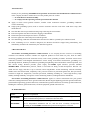
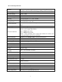
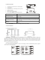
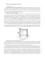
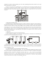
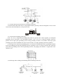
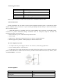
1
Content
Attention Items: ..........................................................................................................................................................3
I. Brief Introduction ....................................................................................................................................................3
II. Model Difference ...................................................................................................................................................3
III. Technical Specifications .......................................................................................................................................4
IV. Detector Structure .................................................................................................................................................5
V. Network Structure ..................................................................................................................................................5
VI. The Principle and Application of Detection .........................................................................................................6
VII. Wiring Instructions .............................................................................................................................................9
VIII. Install Caution ...................................................................................................................................................9
IX. Power Supply Way Choice ...................................................................................................................................9
X. Basic Equipment....................................................................................................................................................9
2
Attention Items:
l
l
l
l
l
l
l
l
Thank you for purchasing ETCR2800 series products Non-Contact Ground Resistance Online Detector
of the company In order to make better use of the product please be certain:
——To read this user manual carefully.
——To comply with the operating cautions presented in this manual.
Apply to return circuit ground resistance, metallic return connection resistance, grounding conditions
on-line monitoring.
Single point grounding system, needs to increase assistance after the ends of the earth form a loop, then
install detector.
Note that this detector specified measuring range and using the environment.
Protection against rain shower and water logging of installation.
Install waterproof and rainproof of device at outdoors.
Detector signal line connected port towards the ground.
The dismantling, calibration and maintenance the Detector shall be operated by the authorized staff.
If the continuing use of it would be dangerous, the Detector should be stopped using immediately, and
immediately sealed for the treatment by the authorized agencies.
I. Brief Introduction
Non-Contact Grounding Resistance Online Detector is our company devotes ourselves to Grounding
resistance test technical research’s another new high-tech product for more than ten years, built for online
monitoring grounding down lead connection status, return circuit grounding resistance and metal return circuit
connection resistance well-designed manufactured. on-line testing, non-contact measurement, grounding wire
pass through the hole, definitely not influence grounding for lightening effect and facilities’ normal operation, real
time on-line testing. Detector provides power supply and RS485 signal interface, provides standard
MODBUS-RTU communication protocol, which is convenient for doing second development. Detector can
install and use singly, and also set up a network, realize long-distance on-line monitoring. Detector internally
installs sensor and circuit board, completely seals, possesses features of protection against rain, dust prevention,
resistance to high low temperature, corrosion prevention, inflaming retarding etc., ensure high-accuracy, high
stability and high reliability of long time on-line monitoring outdoors, underground mine and indoors.
Non-Contact Grounding Resistance Online Detector applies to electric transmission line pole ground
connection, underground mine device ground connection, Meteorological lightning protection ground connection,
petrochemical engineering ground connection, communication ground connection, rail facility ground connection,
building the warehouse ground connection, electrical equipment ground connection etc..
II. Model Difference
Model
Difference Explanation
ETCR2800B
Detector without display, user needs to do secondary development according to offered
RS485 communication protocol, to monitor the detection data.
ETCR2800C
Detector owns LCD display, Alarm setting, audible and visual alarm instructions and
can be independent installation and use, and also does secondary development
according to offered RS485 communication protocol and organizes a network.
3
III. Technical Specifications
Function
Return circuit grounding resistance on-line monitoring, metal return
resistance connection online monitoring, grounding condition monitoring.
Power Supply
Detector: DC6V~DC9V,50ma Max.
Resistance Range
0.01Ω~200Ω
Resolution
0.001Ω
Indication Range
0.00Ω~500Ω
Accuracy
±2%rdg±3dgt(20℃±5℃, below 70%RH)
Grounding Wire
Perforation Size
60mm×30mm, closed mode
diameterФ30mm electric cable)
Overflow Indication
When show value is beyond 500Ω, systems software and LCD show “OLΩ”
sign.
Connecting Line
A one meter long wire(5cores shielded wire)
Connection Identifier
Red/brown---power supply input anode;
Black--- power supply input cathode;
Blue---RS485 signal anode;
Grey---RS485 signal cathode;
White--- analog grounding (power supply input cathode can connects with
analog grounding by short circuit connection)
Protocol Standard
RS485 standard MODBUS-RTU communication protocol
Alarm Indication
ETCR2800C:Detector Audible and visual alarm instructions
Alarm Setting
ETCR2800C:Detector panel setting
Data Display
ETCR2800C:4digits LCD direct indication
LCD Dimensions
47mm×28.5mm
Detector Dimensions
175mm×170mm×130mm
Installing Screw Hole Size
Φ8mm
Quality
Detector: 960g
Working Temperature And
Humidity
-20℃~55℃;20%RH~90%RH
Humiture Error
Within 5%
Shift
Automatic shift
GND Interference Current
Prohibited
External Magnetic Field
<40A/m
External Electric Field
<1V/m
Single Measurement Of
Time
About 0.5 second
Power Consumption
Detector: 50ma Max.
Installation
Grounding wire through Detector centre bore
Level Of Protection
IP65
Installation Requirements
Avoid rain and water logging
Power Supply Mode
External power supply (Equipped by user)
4
(60mm×4mm
steel
flat
or
external
IV. Detector Structure
1.
2.
3.
4.
5.
6.
Grounding wire perforation size: 60mm×30mm.
LCD displayer.
Up and down cover connecting screws (6 pieces).
Install screw holes.
Button and the indicator light.
Power supply, RS485 communication interface.
Power Supply Indicator Light
Working indication when power supply switches on.
Alarm Indicator Light
Alarm light switches on when measured value is beyond pre-set
critical value.
SET Key
Enter setup
Up and Down Arrow Key
Press SET key to enter the alarm setting, press up and down arrow
key to set value.
Enter Key
After setting up alarm critical value, press ENTER key to ensure
saving.
Note: ETCR2800B mode without LCD display and press key function.
V. Network Structure
1. Independent Installation and Use.
ETCR2800C can be installed and used independently, also can develop system software on their own
according to offered RS485 communication protocol, organizes a network monitor. LCD shows measured value
directly, also sets up Detector’s alarm critical value, and possess audible and visual alarming function. When
independent installation it can use 2 batteries instead of power supply, or use solar cell panel to charge batteries,
batteries need placing in the protection box.
2. Reference of Network Organization.
Users can develop system software on their own according to offered communication protocol, organize
wired network, as the picture below.
Cable Network System
Wireless Network System
5
VI. The Principle and Application of Detection
1. Testing Principle.
Non-Contact Grounding Resistance Online Detector’s fundamental is measuring return circuit resistance.
firstly Sensor send out a drive pulse signal to be measured ground return circuit, then measured ground return
circuit responses a pulse electromotive force E, under the influence of electromotive force E there will generate
current I in the be measured ground return circuit. Sensor measures E and I, and immediately gets resistance of be
measured ground return circuit through the formula: R=E/I.
2. Return Circuit Resistance Definition.
As picture: return circuit is a composite value includes A spot grounding resistance, grounding down lead
metallic conductor’s resistance, metal overhead line’s resistance, connection resistance(contact resistance)between
grounding down lead and metal overhead line, B spot grounding resistance. For the formative above-mentioned
return circuit’s grounding system, Detector can be installed directly for monitoring, if the grounding system not
form a return circuit, it need adding auxiliary grounding electrode to form a return circuit, further install the
Detector, see the after-mentioned single point grounding system. If the Detector measured out return circuit’s
composite value of grounding network A and grounding network B is 5.0Ω, that is: RA+RB+RC+ RD =5.0Ω(RC
and RD respectively represent resistance of metal overhead line and grounding down lead ), actual grounding
resistance value of grounding network A and grounding network B’s in parallel resistances less than or equal to
2.5Ω, accordingly judge actual grounding resistance value of grounding network A and grounding network B
parallel connection whether qualified. If grounding network A and grounding network B’s in parallel resistances
less than engineering standard required value, so grounding network A and grounding network B are all qualified.
3. Metal Return Circuit Connection Resistance Testing.
If grounding network A and grounding network B up and down are connected together on the ground, then
Detector measures out metal return circuit resistance’s value is very small general speaking, only few of an Ohm,
this is the connection resistance of metal return circuit, namely equipotential resistance, isn’t grounding resistance.
Therefore the Detector is also convenient to test metal return circuit’s connection resistance.
In the large-scale grounding grid, such as converting station ground connection, oil depot ground connection,
building construction ground connection and so on, they are all an integral large-scale grounding grid under the
ground, meanwhile there are many grounding down lead extends to the ground, and connects the other on the
ground, as the following picture. To such large-scale grounding grid, its grounding grid’s maximum diagonal
distance is about a few hundred meters to thousands of meters, testing its grounding resistance is very difficult and
troublesome. If it exist unqualified grounding resistance, that problem is appearing at the connection position of
grounding down lead and grounding grid (direction of arrow of the welding position in the picture), engineering
reform is to excavate grounding down lead’s position, then again weld grounding down lead. Actually it’s
6
impossible to reform the whole grounding grid, or the whole grounding grid and surface facilities need to pull
down and rebuild, this is impossible.
Therefore, for the large-scale grounding grid, we can install Detector on the primary grounding down lead
and secondary grounding down lead to monitor connection status between the grounding down lead and the
grounding grid, judge the grounding down lead’s grounding conditions by testing metal return circuit connection
resistance.
4. Single Point Grounding System.
If grounding network A and grounding network B is without overhead line, and doesn’t connect together on
the ground, then grounding network A and grounding network B can regard as standalone single point grounding
connection. Detector cannot test single point grounding system’s grounding resistance directly. This moment it
needs adding one or more auxiliary grounding electrode, to form multipoint return circuit, then to install Detector.
In the small range, if there are two or more single point grounding system, it can use metallic conductor to connect
all single point grounding system’s grounding down lead together on the ground, to form a return circuit, then
install the Detector to monitor.
5. Application.
(1). Power Transmission System Pole Ground Connection.
It forms multipoint grounding system through overhead ground wire connection; test conveniently, its
equivalent circuit as the following picture on the right.
illustration:R1 is predicted grounding resistance, R0 is the equivalent resistance of all the other pole’s
grounding resistance parallel connection, that is R0=R2∥R3∥R4∥…∥Rn, if the greater n is (the more grounded
junction), the closer R0 gets to 0,far smaller than R1, from engineering point of view, R0=0,so, the data Detector
receives should be R1’s value.
(2). Underground Mine Power Transformation Ground Connection.
respectively,primary grounding electrode R,R1~R3…Rn is a independent grounding body under the ground,
don’t connect together, are multipoint grounding system, convenient to test. Detector is installed on the primary
grounding electrode, the Detector’s indication is Rr=R+R1 ∥R2 ∥R3 ∥…∥Rn. If the more part grounded
junctions are, so R1∥R2∥R3∥…∥Rn≈0,then Rr=R. It’s the four-code cable in the picture, one code is ground
lead among it, all the devices and part grounding connection are connected to be a network by cable grounding
connection, dotted line is bare copper wire of grounding connection.
7
(3). Generator Room and Launch Tower Grounding Connection.
Generator Room and Launch Tower is independent outdoors generally, connect both together to form second
return circuit, then install detector, as the picture below.
(4). Construction Grounding Connection.
If R1~R6…Rn is a independent grounding body under the ground, don’t connect together, are multipoint
grounding system, convenient to test grounding resistance. If R1~R6…Rn are connected together under the
ground, for the single point grounding system, testing grounding resistance in accordance with single point
grounding system, direct installation test return circuit resistance, can judge grounding connection condition.
For the large-scale construction grounding grid, it is to monitor its equipotential value of grounding condition
between grounding down lead and grounding network. If problems occur, it would be located at the connection
point between grounding down lead and grounding network, and judging that whether its equipotential value
qualified or not.
(5).Oil Storage Tank’s loading and Unloading Point Grounding Connection.
8
VII. Wiring Instructions
Wire Color
Introductions
Red/Brown
Power Supply Anode
Black
Power Supply Cathode(GND)
Blue
RS485 Signal Positive Electrode
Grey
RS485 Signal Negative Electrode
White
Signal grounding electrode can short connect GND.
When organize a network, it needs connecting Detector in accordance with wire color.
VIII. Install Caution
Special Explanation: only if it forms a return circuit grounding connection system, it could directly install
and use. Otherwise, firstly it needs to set up an auxiliary grounding connection nearby to form a return circuit,
then to install the Detector.
1. Install the Detector to grounding down lead, and grounding down lead needs to unbuckle buckle,
convenient for product maintenance latterly. Installation must be waterproof, rainproof, anti-theft and
breakage-proof and so on in the open air.
2. Notice direction, try to be vertical and wire port downwards.
3. Notice height.
4. Deploy power supply and communication wire on the basis of field and distance.
5. Power supply wire’s polarities connect properly or Detector doesn’t work.
IX. Power Supply Way Choice
1. AC adapter converts power supply’s 220V AC into 6-9V DC, which can supply Detector.
2. 2 pieces standby batteries for alternate use.
3. As the picture below, solar cell panel supply is suitable for the places where can't get electricity. Solar cell
panel’s anode and batteries’ anode needs a fast recovery rectifier forward connection in series (as IN5817), when
using ETCR2800C is convenient.
X. Basic Equipment
Detector
1Set
Connector Wire
1PCS
Packing Box
1 Set
User's Manual, Warranty Manual, Certification
1 Set
9
10
Manufactured by
ETCR Electronic Technology Company
Address: F-3F, No.4 Pengshang Zhifu Road, Jiahe, Baiyun
District, Guangzhou, Guangdong, China
Post Code: 510440
Tel: (86-20)62199556 62199554
Fax: (86-20)62199550
E-mail: [email protected]
Website: www.etcr.cc
11