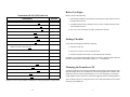
1
Trademarks
®
FrameSaver is a registered trademark of Paradyne Corporation. All other products,
systems, or services mentioned in this document are trademarks, service marks, registered trademarks or registered service marks of their respective owners.
FrameSaver NP
Installation & Quick Reference Guide
FrameSaver NP Models 64+, 100, 110 and 120
Copyright Notice
© Copyright 1999-2000 Paradyne Corporation. All rights reserved.
Document Number 980-000-0272B
August 2000
Sales, Service and Warranty Information
Contact your local service representative, distributor or sales representative for additional information or help concerning service, repair, installation, documentation, warranty or sales. Or contact Paradyne Corporation at:
• Telephone: 201-703-4800
• Internet: http://www.paradyne.com
• FAX: 201-703-4889
This Quick Reference Guide provides an overview on how to install a FrameSaver NP
Model 64+, 100, 110 or 120 unit. This includes making the physical connections between the unit, network, DTE device(s), and telephone line. It also tells you how to find
more detailed information about your FrameSaver NP.
Product Documentation on the World Wide Web
We provide complete product documentation online. This lets you search the documentation for specific topics and print only what you need, reducing the waste of surplus printing. It also helps us provide timely product update information and maintain
competitive prices for our products.
Complete documentation for these products is available at www.paradyne.com.
Select Library → Technical Manuals →
FrameSaver NP (NetPath) Frame Relay Digital Access Units
• Mail: Paradyne Corporation
16-00 Pollitt Drive
Fair Lawn NJ 07410
Select the appropriate document from the documentation list:
FrameSaver NP 64+ User’s Manual - Installation Guide, Publication # 980-001-0221
FrameSaver NP 100 User’s Manual - Installation Guide, Publication # 980-001-0210
FrameSaver NP 110 User’s Manual - Installation Guide, Publication # 980-001-0240
FrameSaver NP 120 User’s Manual - Installation Guide, Publication # 980-001-0230
16
1
Getting Started
Before installing or starting to use the FrameSaver NP, you should:
• Install the User’s Manual - Installation Guide so that you can access all the
installation, configuration, and operating information about the unit.
FrameSaver NP 110 Cable List
Description
Part No.
T1 or DSX network cable, RJ-48, twisted pair
135-982-0006
Dial Line (POTS) cable, RJ-11 connector
135-007-7200
ISDN BRI network cable, RJ-49 connector
135-981-0006
Console cable (to AUX2), DB-9 connector
135-000-0464
Adobe Acrobat Reader may be obtained free from Adobe Systems Incorporated, from
their Web Site at www.adobe.com.
Console cable (to AUX2), DB-25 connector
135-007-0400
AUX Port to router console port cable, DB-25 connector
135-008-0400
Using Adobe Acrobat Reader
AUX Port to Cisco router console port, RJ-45 type connector
135-990-0006
• Print sections you may want to reference.
User’s Manual - Installation Guide
The manual is in PDF file format. Your PC should be using Microsoft Windows 3.1 or
above, and have Adobe Acrobat Reader installed for browsing or printing this manual.
Adobe Acrobat Reader is used just as you would most word processing or text editing
programs. Start Adobe Acrobat Reader and open the file containing the FrameSaver
NP User’s Manual - Installation Guide. You can simply scroll through the pages, or
use the Bookmarks along the left side to move around the manual or the tables in the
front of the manual.
Contact your service representative, distributor or sales representative to order cables.
To print the manual or a selection of pages, select Print... from the File menu and then
select the range of pages you wish to print. Select OK to begin printing.
Ordering a Hard Copy of the User’s Manual
Contact Paradyne Corporation at the address on the back of this Guide to obtain a printed copy of a FrameSaver NP User’s Manual - Installation Guide. Always specify the
“latest revision” for each publication number:
Safety Instructions
Before proceeding with the installation, carefully read the Equipment Interference Notice, Important Safety Instructions and Preface sections of the FrameSaver NP User’s
Manual - Installation Guide.
2
15
Before You Begin
FrameSaver NP 100 (120) Cable List
Description
Ensure you have the following:
Part No.
• A dedicated, grounded, circuit breaker protected power outlet within six feet of
the FrameSaver NP unit.
T1 network cable, RJ-48, twisted pair (NP 100 only)
135-982-0006
Dial Line (POTS) cable, RJ-11 connector (NP 100 only)
135-007-7200
ISDN BRI network cable, RJ-49 connector (NP 100 only)
135-981-0006
EIA-530 Data Port (DTE) cable (NP 100 only)
135-002-0400
EIA-530A Data Port (DTE) cable (NP 100 only)
135-003-0400
ITU-X.21-NS Data Port (DTE) cable (NP 100 only)
135-005-0400
ITU-V.35 Data Port (DTE) cable (NP 100 only)
135-001-0400
ITU-V.35 Data Port (DTE) cable to Cisco router serial port,
HD-60 connector (NP 100 only)
135-006-0400
Console cable (to AUX2), DB-9 connector
135-000-0464
• Unit power cord or AC Power Pack with cord
Console cable (to AUX2), DB-25 connector
135-007-0400
• If ordered, optional wall-mount or rack-mount bracket assembly.
AUX Port to router console port cable, DB-25 connector
135-008-0400
AUX Port to Cisco router console port, RJ-45 type connector
135-990-0006
ITU-V.35 Compliant network cable (NP 120 only)
135-001-0480
ITU-X.21-NS network cable (NP 120 only)
135-005-0480
Mounting the FrameSaver NP
ITU-V.35 Compliant User Port cable (NP 120 only)
135-002-0480
EIA-530 User Port cable (NP 120 only)
135-003-0480
EIA-530A User Port cable (NP 120 only)
135-004-0480
FrameSaver NP units come equipped with rubber feet for table or shelf-top placement.
Optional adapter brackets are available for wall mounting (Model 64+ includes wallmount key-holes in its base) and standard 19" or 24" rack mounting. To attach and
mount adapter brackets, follow the instructions supplied with the mounting adapters.
• A suitable location for the unit that is clean, well-lit, ventilated and free from
environmental extremes.
• One to two feet of clearance for cable connections to the unit.
Package Checklist
Verify that the packaging contains the following:
• FrameSaver NP unit
Contact your service representative, distributor or sales representative to order cables.
14
In addition, you will need Input/Output cables if not already supplied. These cables are
listed for each FrameSaver NP Model on pages 13 - 15 of this guide.
Allow sufficient space for cooling and access to the front panel indicators for troubleshooting in all installations.
3
Power Up a FrameSaver NP 64+
FrameSaver NP 64+ Cable List
Make Power Connections
1. Plug the 2-pin keyed and locking connector at the end of the cord from the AC
Power Pack into the right-most pins of the 4-pin Power Connector located on the
rear of the FrameSaver NP 64+, just to the right of the alert marking.
CAUTION
The power connectors are keyed and fit easily together
when oriented correctly with the locking clip toward the
top of the unit. Do not force the connectors together.
Blocking Safety Plug
(R em ove on ly w hen in sta lling op tional
P ow er C o ntrol U n it)
S EE
U SE RS
M AN U AL
P O W ER
P AC
D IG ITS
x100
x10
D ATA P O R T
x1
O 1 2 3 4 5 6 7 8 9 10 1112
N
D LC I
Plug into RIGHT side
Pins O NLY
Description
Part No.
DDS network cable, RJ-48, twisted pair
135-982-0006
Dial Line (POTS) cable, RJ-11 connector
135-007-7200
ISDN BRI network cable, RJ-49 connector
135-981-0006
EIA-232 Data Port (DTE) cable
135-000-0400
EIA-530 Data Port (DTE) cable
135-002-0400
EIA-530A Data Port (DTE) cable
135-003-0400
ITU-X.21-NS Data Port (DTE) cable
135-005-0400
ITU-V.35 Data Port (DTE) cable
135-001-0400
ITU-V.35 Data Port (DTE) cable to Cisco router serial port,
HD-60 connector
135-006-0400
Console cable (to AUX2), DB-9 connector
135-000-0464
Console cable (to AUX2), DB-25 connector
135-007-0400
AUX Port to router console port cable, DB-25 connector
135-008-0400
AUX Port to Cisco router console port, RJ-45 type connector
135-990-0006
Contact your service representative, distributor or sales representative to order cables.
2-Pin
Connector
from
Pow er Pack
CAUTION
The 2-pin keyed plug fits easily into the two RIGHT-SIDE pins of the 4-pin
Power Connector, and must only be inserted there. The FrameSaver NP
unit will be damaged if the plug is forced into the other side.
4
13
FrameSaver NP 110 Specifications
2. Plug the Power Pac at the other end of the power cord into an AC outlet.
3. The unit will go through the following power-up sequence:
Item
Dimensions
Description
Table Top (with rubber feet):
3.5" H x 10.5" W x 12.0"D.
Wall Mount (with removable wall mounting bracket):
10.5" H x 12.0" W x 3.5" D.
Rack Mount (with removable rack mounting adapter):
5.25" H x 19.0" W ( or 24.0" W ) x 12.0" D.
Weight
As normally packaged including carton and accessories: 8 lbs.
Unit alone (without packaging and accessories): 6 lbs.
Operating
Range
Temperature: 0 to 50 degrees C. operating.
Relative Humidity: 5 to 95% non-condensing.
Altitude: 10,000 ft. max. operating,
50,000 ft. max. non-operating.
Shock and Vibration: As normally encountered during shipping
and handling.
Power
Requirements
Regulatory
Compliance
AC Input 100 - 240 VAC, 50 - 60 Hz., 5.0A max.
0.5A max. for the unit’s internal power requirements.
4.5 A max. for device (if any) connected to the Switched AC
Output.
Fused - 5A/250V Slow Blow, 5x20mm.
Switched AC Output: max, 250 VAC, 4.5 A.
CAUTION:
FOR CONTINUED PROTECTION AGAINST RISK OF FIRE,
REPLACE FUSE ONLY WITH THE SAME TYPE AND
RATING.
ATTENTION:
POUR NE PAS COMPROMETTRE LA PROTECTION
CONTRE LE RISQUE D’INCENDIE REMPLACER PAR UN
FUSIBLE DE MEMES TYPE ET CARACTERISTIQUE
NOMINALES.
UL - 1950, Third Edition and CAN/CSA C22.2 No. 950-95,
Third Edition, FCC Part 15, Class A Digital Device,
Canada’s ICES003, Class A Digital Device, FCC Part 68
12
FrameSaver NP 64+ Power-Up Sequence
Basic FrameSaver NP 64+
FrameSaver NP 64+ with ISDN
POWER LED lights and stays on.
READY LED may flash several times,
then remain OFF during self-test
(approximately 45 seconds).
READY and ISDN READY LEDs
may flash several times, then remain
OFF during self-test (approximately 45
seconds).
READY LED is ON steady after
completion of self-test.
READY and ISDN READY LEDs are
ON steady after completion of self-test.
The DDS ALARM and FR MGMT. LEDs should not be flashing together.
All other LED indications should be ignored at this time.
If the LED indications are not as described above, refer to Section 5, “Diagnostics” of
the FrameSaver NP 64+ User’s Manual - Installation Guide.
If operation looks normal, unplug the FrameSaver NP before making input/output connections.
If an optional Power Control Unit (PCU) is to be installed with this FrameSaver NP,
refer to the instructions provided with the PCU and install it now.
Proceed to Making Network and Input/Output Connections on page 9 of this guide.
5
Power Up a FrameSaver NP 100
FrameSaver NP 100 (120) Specifications
Power Connections
Item
1. Plug the IEC 320 end of the Power Cord into the connector on the rear of the
FrameSaver NP.
AC Power Connector
Dimensions
Table Top (with rubber feet):
3.5" H x 10.5" W x 12.0"D.
Wall Mount (with removable wall mounting bracket):
10.5" H x 12.0" W x 3.5" D.
Rack Mount (with removable rack mounting adapter):
5.25" H x 19.0" W ( or 24.0" W ) x 12.0" D.
Weight
As normally packaged including carton and accessories: 8 lbs.
Unit alone (without packaging and accessories): 6 lbs.
Operating
Range
Temperature: 0 to 50 degrees C. operating.
Relative Humidity: 5 to 95% non-condensing.
Altitude: 10,000 ft. max. operating,
50,000 ft. max. non-operating.
Shock and Vibration: As normally encountered during shipping
and handling.
Power
Requirements
90 - 250 VAC, 50 - 60 Hz.,15 Watts max.
(100 - 240 VAC for FrameSaver NP 120)
Fused - 2A/250V Slow Blow, 5x20mm.
CAUTION:
FOR CONTINUED PROTECTION AGAINST RISK OF FIRE,
REPLACE FUSE ONLY WITH THE SAME TYPE AND
RATING.
ATTENTION:
POUR NE PAS COMPROMETTRE LA PROTECTION
CONTRE LE RISQUE D’INCENDIE REMPLACER PAR UN
FUSIBLE DE MEMES TYPE ET CARACTERISTIQUE
NOMINALES.
Regulatory
Compliance
FrameSaver NP 100: UL - 1459, Third Edition and CAN/CSA
C22.2 No. 225-M90; FCC Part 15, Class A Digital Device;
FCC part 68;Canada’s ICES003, Class A Digital Device
FrameSaver NP 120: UL-1950; CAN/CSA C22.2 No. 225-M90;
FCC Part 15, Class B Digital Device; Canada’s ICES003,
Class A Digital Device; EN 60950; EN 50082-1:1992;
EN 55022:1995; EMI: EN 55022 Class B
9 0-2 5 0 V AC
.5A
5 0-6 0 H z
IEC 320 (male)
FU S E
2 A/25 0 V
S L O W B LO W
5 x2 0 m m
"C AU TIO N "
FO R CO NTIN UED PRO TECT ION AG AINST R ISK O F FIRE,
REPLACE O NLY WITH SAME T YPE AN D RAT IN G O F FUSE.
O 1 2 3 4 5 6 7 8 9 1 0 1 11 2
N
2. Plug the other end of the
Power Cord into an AC outlet.
O 1 2
N
C O N FIG U RATIO N
C O N TRO L
O U TP U T
D ATA P O R
3. The unit will go through the following power-up sequence
FrameSaver NP 100 Power-Up Sequence
Basic FrameSaver NP 100
FrameSaver NP 100 with ISDN
POWER LED lights and stays on.
READY LED flashes during self-test
(approximately 60 seconds).
READY and ISDN READY LEDs
flash during self-test (approximately 60
seconds).
READY LED is ON steady after
completion of self-test.
READY and ISDN READY LEDs are
ON steady after completion of self-test.
The T1 ALARM and FR MGMT. LEDs should not be flashing together.
All other LED indications should be ignored at this time.
If the LED indications are not as described above, refer to Section 5, “Diagnostics” of
the FrameSaver NP 100 User’s Manual - Installation Guide. If operation looks normal, unplug the FrameSaver NP before making input/output connections.
If an optional Power Control Unit (PCU) is to be installed with this FrameSaver NP,
refer to instructions provided with the PCU and install it now.
Proceed to Making Network and Input/Output Connections on page 9 of this guide.
6
Description
11
Making DROP/DSX Option Connections (FrameSaver NP 110 only)
FrameSaver NP 110 units equipped with optional DROP/DSX adapters have additional connectors on the rear panel for the DROP and DSX Ports. The DROP Port supports
the ITU-V.35 interface and the DSX Port is aT1 Network interface.
FrameSaver NP 64+ Specifications
Item
Dimensions
Description
Table Top (with rubber feet):
3.0" H x 8.5" W x 11.5" D.
Wall Mount (with removable wall mounting bracket):
8.5" H x 11.5" W x 3.0" D.
Rack Mount (with removable rack mounting adapter):
3.5" H x 19.0" W ( or 24.0" W ) x 11.5" D.
Weight
As normally packaged including carton and accessories: 6 lbs.
Unit alone (without packaging and accessories): 4 lbs.
Operating
Range
Power
Requirements
Regulatory
Compliance
Temperature: 0 to 50 degrees C. operating.
Relative Humidity: 5 to 95% non-condensing.
Altitude: 10,000 ft. max. operating,
50,000 ft. max. non-operating.
Shock and Vibration: As normally encountered during
shipping and handling.
AC Power Pack (transformer/plug module).
Input = 90 - 130 VAC, 0.2 A max., 60 Hz.
Output = 22 VAC, 30 VA.
Cable: 2-conductor, with 2-pin keyed locking connector,
7 ft. length.
UL - 1459, Third Edition and CAN/CSA C22.2 No. 225-M90
FCC Part 15, Class A Digital Device
Canada’s ICES003, Class A Digital Device
FCC Part 68
Power Up a FrameSaver NP 110
Power Connections
1. Plug the IEC 320 end of the Power Cord into the connector on the rear of the
FrameSaver NP 120.
AC Power Connector
S W ITC H E D
AC OU T
2 50 V A C
4 .5A M A X
O 1 2
N
IEC 320 (male)
1 00 -24 0 V A C
5A
5 0-6 0 H z
2. Plug the other end of the Power
Cord into an AC outlet.
USER PORT
12
"C AU TIO N "
FO R C O N T IN U E D
P R O TE C TIO N
A G A IN S T R IS K
O F FIR E ,
R E P L A C E O N LY
W ITH S AM E TY P E
A N D R A TIN G
O F FU S E .
FU S E
5 A/2 5 0 V
S LO W B L O W
5 x2 0 m m
3. The unit will go through the following power-up sequence
FrameSaver NP 110 Power-Up Sequence
Basic FrameSaver NP 110
FrameSaver NP 110 with ISDN
UNIT POWER LED lights and stays on.
UNIT READY LED flashes during
self-test (approximately 60 seconds).
UNIT READY and ISDN READY
LEDs flash during self-test
(approximately 60 seconds).
UNIT READY LED is ON steady after
completion of self-test.
UNIT READY and ISDN READY
LEDs are ON steady after completion
of self-test.
NETW ALARM and UNIT FRM MGMT LEDs should not be flashing together.
All other LED indications should be ignored at this time.
If the LED indications are not as described above, refer to Section 5, “Diagnostics” of
the FrameSaver NP 110 User’s Manual - Installation Guide. If operation looks normal, unplug the FrameSaver NP before making input/output connections.
If the unit is to supply switched power to another device, plug that device’s power cord
into the Switched AC Out connector now.
Proceed to Making Network and Input/Output Connections on page 9 of this guide.
10
7
Making Network and Input/Output Connections
Power Up a FrameSaver NP 120
CAUTION
Power Connections
Be sure you remove AC power from the FrameSaver NP
before attaching input and output cables.
1. Plug the IEC 320 end of the Power Cord into the connector on the rear of the
FrameSaver NP.
AC Power Connector
All connectors are located on the FrameSaver NP’s rear panel.
"C AU TIO N"
FO R C O N TIN U E D P R O TE CTIO N AG AINS T
R IS K O F F IR E , R E P L AC E O NL Y W ITH
S AM E TY P E AN D R ATIN G O F F U S E .
IEC 320 (male)
Make all the necessary connections using the cables listed for that model.
1 00 -2 40 V AC
.5A
5 0-6 0 H z
2. Plug the other end of the Power
Cord into an AC outlet.
FU S E
2 A/2 5 0V
S L O W B LO W
5 x2 0 m m
CAUTION
O 1 2 3 4 5 6 7 8 9 10 1112
N
O 1 2
N
C O N FIG U RATIO N
C O N TRO L
O U TP U T
USER P OR
3. The unit will go through the following power-up sequence
Use caution when connecting to an AUX Port. AUX Port
connectors are similar to the Network connectors.
Accidental connection of either of the AUX Ports to a
Network facility may damage the AUX Port electrical
interface.
FrameSaver NP 120 Power-Up Sequence
FrameSaver NP 120
POWER LED lights and stays on.
READY LED flashes during self-test (approximately 30 seconds).
READY LED is ON steady after completion of self-test.
The NETWORK ALARM and FR MGMT. LEDs should not be flashing together.
Refer to User’s Manual - Installation Guide if they are.
All other LED indications should be ignored at this time.
NOTES:
1. FrameSaver NP 64+, 100, and 120 Data and User Ports support numerous
electrical interface types; ITU-V.35, EIA-530, EIA-530-A, ITU-X.21-NS and
EIA-232 (FrameSaver NP 64+ only). The Data Port connector is a DB-44 high
density female. The adapter cables listed for each model are used to convert from
the DB-44 to the appropriate connector type for the interface selected. The adapter
cable also includes a special wiring pattern at the DB-44 connector, which
automatically sets the port to the desired interface type. Refer to the tables on
pages 13 - 15 of this guide for cable ordering information if necessary.
2. FrameSaver NP 110 User and Data Ports are configured for ITU-V.35 Interface.
If the LED indications are not as described above, refer to Section 5, “Diagnostics” of
the FrameSaver NP 120 User’s Manual - Installation Guide. If operation looks normal, unplug the FrameSaver NP before making input/output connections.
3. FrameSaver NP 120 is designed for use in networks where it is not directly
connected to the local PTT’s (non-U.S.) facilities. All the Network connections are
made to the customer’s Private Network.
If an optional Power Control Unit (PCU) is to be installed with this FrameSaver NP,
refer to instructions provided with the PCU and install it now.
Making ISDN Option Connections
Proceed to Making Network and Input/Output Connections on the next page of this
guide.
8
FrameSaver NP units equipped with optional ISDN adapters have additional connectors on the rear panel for ISDN Line(s) and ISDN Data Port (DTE). The ISDN Data
Port supports the same electrical interface types and uses the same connector as the
base unit Data Port.
9
Making DROP/DSX Option Connections (FrameSaver NP 110 only)
FrameSaver NP 110 units equipped with optional DROP/DSX adapters have additional connectors on the rear panel for the DROP and DSX Ports. The DROP Port supports
the ITU-V.35 interface and the DSX Port is aT1 Network interface.
FrameSaver NP 64+ Specifications
Item
Dimensions
Description
Table Top (with rubber feet):
3.0" H x 8.5" W x 11.5" D.
Wall Mount (with removable wall mounting bracket):
8.5" H x 11.5" W x 3.0" D.
Rack Mount (with removable rack mounting adapter):
3.5" H x 19.0" W ( or 24.0" W ) x 11.5" D.
Weight
As normally packaged including carton and accessories: 6 lbs.
Unit alone (without packaging and accessories): 4 lbs.
Operating
Range
Power
Requirements
Regulatory
Compliance
Temperature: 0 to 50 degrees C. operating.
Relative Humidity: 5 to 95% non-condensing.
Altitude: 10,000 ft. max. operating,
50,000 ft. max. non-operating.
Shock and Vibration: As normally encountered during
shipping and handling.
AC Power Pack (transformer/plug module).
Input = 90 - 130 VAC, 0.2 A max., 60 Hz.
Output = 22 VAC, 30 VA.
Cable: 2-conductor, with 2-pin keyed locking connector,
7 ft. length.
UL - 1459, Third Edition and CAN/CSA C22.2 No. 225-M90
FCC Part 15, Class A Digital Device
Canada’s ICES003, Class A Digital Device
FCC Part 68
Power Up a FrameSaver NP 110
Power Connections
1. Plug the IEC 320 end of the Power Cord into the connector on the rear of the
FrameSaver NP 120.
AC Power Connector
S W ITC H E D
AC OU T
2 50 V A C
4 .5A M A X
O 1 2
N
IEC 320 (male)
1 00 -24 0 V A C
5A
5 0-6 0 H z
2. Plug the other end of the Power
Cord into an AC outlet.
USER PORT
12
"C AU TIO N "
FO R C O N T IN U E D
P R O TE C TIO N
A G A IN S T R IS K
O F FIR E ,
R E P L A C E O N LY
W ITH S AM E TY P E
A N D R A TIN G
O F FU S E .
FU S E
5 A/2 5 0 V
S LO W B L O W
5 x2 0 m m
3. The unit will go through the following power-up sequence
FrameSaver NP 110 Power-Up Sequence
Basic FrameSaver NP 110
FrameSaver NP 110 with ISDN
UNIT POWER LED lights and stays on.
UNIT READY LED flashes during
self-test (approximately 60 seconds).
UNIT READY and ISDN READY
LEDs flash during self-test
(approximately 60 seconds).
UNIT READY LED is ON steady after
completion of self-test.
UNIT READY and ISDN READY
LEDs are ON steady after completion
of self-test.
NETW ALARM and UNIT FRM MGMT LEDs should not be flashing together.
All other LED indications should be ignored at this time.
If the LED indications are not as described above, refer to Section 5, “Diagnostics” of
the FrameSaver NP 110 User’s Manual - Installation Guide. If operation looks normal, unplug the FrameSaver NP before making input/output connections.
If the unit is to supply switched power to another device, plug that device’s power cord
into the Switched AC Out connector now.
Proceed to Making Network and Input/Output Connections on page 9 of this guide.
10
7
Power Up a FrameSaver NP 100
FrameSaver NP 100 (120) Specifications
Power Connections
Item
1. Plug the IEC 320 end of the Power Cord into the connector on the rear of the
FrameSaver NP.
AC Power Connector
Dimensions
Table Top (with rubber feet):
3.5" H x 10.5" W x 12.0"D.
Wall Mount (with removable wall mounting bracket):
10.5" H x 12.0" W x 3.5" D.
Rack Mount (with removable rack mounting adapter):
5.25" H x 19.0" W ( or 24.0" W ) x 12.0" D.
Weight
As normally packaged including carton and accessories: 8 lbs.
Unit alone (without packaging and accessories): 6 lbs.
Operating
Range
Temperature: 0 to 50 degrees C. operating.
Relative Humidity: 5 to 95% non-condensing.
Altitude: 10,000 ft. max. operating,
50,000 ft. max. non-operating.
Shock and Vibration: As normally encountered during shipping
and handling.
Power
Requirements
90 - 250 VAC, 50 - 60 Hz.,15 Watts max.
(100 - 240 VAC for FrameSaver NP 120)
Fused - 2A/250V Slow Blow, 5x20mm.
CAUTION:
FOR CONTINUED PROTECTION AGAINST RISK OF FIRE,
REPLACE FUSE ONLY WITH THE SAME TYPE AND
RATING.
ATTENTION:
POUR NE PAS COMPROMETTRE LA PROTECTION
CONTRE LE RISQUE D’INCENDIE REMPLACER PAR UN
FUSIBLE DE MEMES TYPE ET CARACTERISTIQUE
NOMINALES.
Regulatory
Compliance
FrameSaver NP 100: UL - 1459, Third Edition and CAN/CSA
C22.2 No. 225-M90; FCC Part 15, Class A Digital Device;
FCC part 68;Canada’s ICES003, Class A Digital Device
FrameSaver NP 120: UL-1950; CAN/CSA C22.2 No. 225-M90;
FCC Part 15, Class B Digital Device; Canada’s ICES003,
Class A Digital Device; EN 60950; EN 50082-1:1992;
EN 55022:1995; EMI: EN 55022 Class B
9 0-2 5 0 V AC
.5A
5 0-6 0 H z
IEC 320 (male)
FU S E
2 A/25 0 V
S L O W B LO W
5 x2 0 m m
"C AU TIO N "
FO R CO NTIN UED PRO TECT ION AG AINST R ISK O F FIRE,
REPLACE O NLY WITH SAME T YPE AN D RAT IN G O F FUSE.
O 1 2 3 4 5 6 7 8 9 1 0 1 11 2
N
2. Plug the other end of the
Power Cord into an AC outlet.
O 1 2
N
C O N FIG U RATIO N
C O N TRO L
O U TP U T
D ATA P O R
3. The unit will go through the following power-up sequence
FrameSaver NP 100 Power-Up Sequence
Basic FrameSaver NP 100
FrameSaver NP 100 with ISDN
POWER LED lights and stays on.
READY LED flashes during self-test
(approximately 60 seconds).
READY and ISDN READY LEDs
flash during self-test (approximately 60
seconds).
READY LED is ON steady after
completion of self-test.
READY and ISDN READY LEDs are
ON steady after completion of self-test.
The T1 ALARM and FR MGMT. LEDs should not be flashing together.
All other LED indications should be ignored at this time.
If the LED indications are not as described above, refer to Section 5, “Diagnostics” of
the FrameSaver NP 100 User’s Manual - Installation Guide. If operation looks normal, unplug the FrameSaver NP before making input/output connections.
If an optional Power Control Unit (PCU) is to be installed with this FrameSaver NP,
refer to instructions provided with the PCU and install it now.
Proceed to Making Network and Input/Output Connections on page 9 of this guide.
6
Description
11
FrameSaver NP 110 Specifications
2. Plug the Power Pac at the other end of the power cord into an AC outlet.
3. The unit will go through the following power-up sequence:
Item
Dimensions
Description
Table Top (with rubber feet):
3.5" H x 10.5" W x 12.0"D.
Wall Mount (with removable wall mounting bracket):
10.5" H x 12.0" W x 3.5" D.
Rack Mount (with removable rack mounting adapter):
5.25" H x 19.0" W ( or 24.0" W ) x 12.0" D.
Weight
As normally packaged including carton and accessories: 8 lbs.
Unit alone (without packaging and accessories): 6 lbs.
Operating
Range
Temperature: 0 to 50 degrees C. operating.
Relative Humidity: 5 to 95% non-condensing.
Altitude: 10,000 ft. max. operating,
50,000 ft. max. non-operating.
Shock and Vibration: As normally encountered during shipping
and handling.
Power
Requirements
Regulatory
Compliance
AC Input 100 - 240 VAC, 50 - 60 Hz., 5.0A max.
0.5A max. for the unit’s internal power requirements.
4.5 A max. for device (if any) connected to the Switched AC
Output.
Fused - 5A/250V Slow Blow, 5x20mm.
Switched AC Output: max, 250 VAC, 4.5 A.
CAUTION:
FOR CONTINUED PROTECTION AGAINST RISK OF FIRE,
REPLACE FUSE ONLY WITH THE SAME TYPE AND
RATING.
ATTENTION:
POUR NE PAS COMPROMETTRE LA PROTECTION
CONTRE LE RISQUE D’INCENDIE REMPLACER PAR UN
FUSIBLE DE MEMES TYPE ET CARACTERISTIQUE
NOMINALES.
UL - 1950, Third Edition and CAN/CSA C22.2 No. 950-95,
Third Edition, FCC Part 15, Class A Digital Device,
Canada’s ICES003, Class A Digital Device, FCC Part 68
12
FrameSaver NP 64+ Power-Up Sequence
Basic FrameSaver NP 64+
FrameSaver NP 64+ with ISDN
POWER LED lights and stays on.
READY LED may flash several times,
then remain OFF during self-test
(approximately 45 seconds).
READY and ISDN READY LEDs
may flash several times, then remain
OFF during self-test (approximately 45
seconds).
READY LED is ON steady after
completion of self-test.
READY and ISDN READY LEDs are
ON steady after completion of self-test.
The DDS ALARM and FR MGMT. LEDs should not be flashing together.
All other LED indications should be ignored at this time.
If the LED indications are not as described above, refer to Section 5, “Diagnostics” of
the FrameSaver NP 64+ User’s Manual - Installation Guide.
If operation looks normal, unplug the FrameSaver NP before making input/output connections.
If an optional Power Control Unit (PCU) is to be installed with this FrameSaver NP,
refer to the instructions provided with the PCU and install it now.
Proceed to Making Network and Input/Output Connections on page 9 of this guide.
5
Power Up a FrameSaver NP 64+
FrameSaver NP 64+ Cable List
Make Power Connections
1. Plug the 2-pin keyed and locking connector at the end of the cord from the AC
Power Pack into the right-most pins of the 4-pin Power Connector located on the
rear of the FrameSaver NP 64+, just to the right of the alert marking.
CAUTION
The power connectors are keyed and fit easily together
when oriented correctly with the locking clip toward the
top of the unit. Do not force the connectors together.
Blocking Safety Plug
(R em ove on ly w hen in sta lling op tional
P ow er C o ntrol U n it)
S EE
U SE RS
M AN U AL
P O W ER
P AC
D IG ITS
x100
x10
D ATA P O R T
x1
O 1 2 3 4 5 6 7 8 9 10 1112
N
D LC I
Plug into RIGHT side
Pins O NLY
Description
Part No.
DDS network cable, RJ-48, twisted pair
135-982-0006
Dial Line (POTS) cable, RJ-11 connector
135-007-7200
ISDN BRI network cable, RJ-49 connector
135-981-0006
EIA-232 Data Port (DTE) cable
135-000-0400
EIA-530 Data Port (DTE) cable
135-002-0400
EIA-530A Data Port (DTE) cable
135-003-0400
ITU-X.21-NS Data Port (DTE) cable
135-005-0400
ITU-V.35 Data Port (DTE) cable
135-001-0400
ITU-V.35 Data Port (DTE) cable to Cisco router serial port,
HD-60 connector
135-006-0400
Console cable (to AUX2), DB-9 connector
135-000-0464
Console cable (to AUX2), DB-25 connector
135-007-0400
AUX Port to router console port cable, DB-25 connector
135-008-0400
AUX Port to Cisco router console port, RJ-45 type connector
135-990-0006
Contact your service representative, distributor or sales representative to order cables.
2-Pin
Connector
from
Pow er Pack
CAUTION
The 2-pin keyed plug fits easily into the two RIGHT-SIDE pins of the 4-pin
Power Connector, and must only be inserted there. The FrameSaver NP
unit will be damaged if the plug is forced into the other side.
4
13
Before You Begin
FrameSaver NP 100 (120) Cable List
Description
Ensure you have the following:
Part No.
• A dedicated, grounded, circuit breaker protected power outlet within six feet of
the FrameSaver NP unit.
T1 network cable, RJ-48, twisted pair (NP 100 only)
135-982-0006
Dial Line (POTS) cable, RJ-11 connector (NP 100 only)
135-007-7200
ISDN BRI network cable, RJ-49 connector (NP 100 only)
135-981-0006
EIA-530 Data Port (DTE) cable (NP 100 only)
135-002-0400
EIA-530A Data Port (DTE) cable (NP 100 only)
135-003-0400
ITU-X.21-NS Data Port (DTE) cable (NP 100 only)
135-005-0400
ITU-V.35 Data Port (DTE) cable (NP 100 only)
135-001-0400
ITU-V.35 Data Port (DTE) cable to Cisco router serial port,
HD-60 connector (NP 100 only)
135-006-0400
Console cable (to AUX2), DB-9 connector
135-000-0464
• Unit power cord or AC Power Pack with cord
Console cable (to AUX2), DB-25 connector
135-007-0400
• If ordered, optional wall-mount or rack-mount bracket assembly.
AUX Port to router console port cable, DB-25 connector
135-008-0400
AUX Port to Cisco router console port, RJ-45 type connector
135-990-0006
ITU-V.35 Compliant network cable (NP 120 only)
135-001-0480
ITU-X.21-NS network cable (NP 120 only)
135-005-0480
Mounting the FrameSaver NP
ITU-V.35 Compliant User Port cable (NP 120 only)
135-002-0480
EIA-530 User Port cable (NP 120 only)
135-003-0480
EIA-530A User Port cable (NP 120 only)
135-004-0480
FrameSaver NP units come equipped with rubber feet for table or shelf-top placement.
Optional adapter brackets are available for wall mounting (Model 64+ includes wallmount key-holes in its base) and standard 19" or 24" rack mounting. To attach and
mount adapter brackets, follow the instructions supplied with the mounting adapters.
• A suitable location for the unit that is clean, well-lit, ventilated and free from
environmental extremes.
• One to two feet of clearance for cable connections to the unit.
Package Checklist
Verify that the packaging contains the following:
• FrameSaver NP unit
Contact your service representative, distributor or sales representative to order cables.
14
In addition, you will need Input/Output cables if not already supplied. These cables are
listed for each FrameSaver NP Model on pages 13 - 15 of this guide.
Allow sufficient space for cooling and access to the front panel indicators for troubleshooting in all installations.
3
Getting Started
Before installing or starting to use the FrameSaver NP, you should:
• Install the User’s Manual - Installation Guide so that you can access all the
installation, configuration, and operating information about the unit.
FrameSaver NP 110 Cable List
Description
Part No.
T1 or DSX network cable, RJ-48, twisted pair
135-982-0006
Dial Line (POTS) cable, RJ-11 connector
135-007-7200
ISDN BRI network cable, RJ-49 connector
135-981-0006
Console cable (to AUX2), DB-9 connector
135-000-0464
Adobe Acrobat Reader may be obtained free from Adobe Systems Incorporated, from
their Web Site at www.adobe.com.
Console cable (to AUX2), DB-25 connector
135-007-0400
AUX Port to router console port cable, DB-25 connector
135-008-0400
Using Adobe Acrobat Reader
AUX Port to Cisco router console port, RJ-45 type connector
135-990-0006
• Print sections you may want to reference.
User’s Manual - Installation Guide
The manual is in PDF file format. Your PC should be using Microsoft Windows 3.1 or
above, and have Adobe Acrobat Reader installed for browsing or printing this manual.
Adobe Acrobat Reader is used just as you would most word processing or text editing
programs. Start Adobe Acrobat Reader and open the file containing the FrameSaver
NP User’s Manual - Installation Guide. You can simply scroll through the pages, or
use the Bookmarks along the left side to move around the manual or the tables in the
front of the manual.
Contact your service representative, distributor or sales representative to order cables.
To print the manual or a selection of pages, select Print... from the File menu and then
select the range of pages you wish to print. Select OK to begin printing.
Ordering a Hard Copy of the User’s Manual
Contact Paradyne Corporation at the address on the back of this Guide to obtain a printed copy of a FrameSaver NP User’s Manual - Installation Guide. Always specify the
“latest revision” for each publication number:
Safety Instructions
Before proceeding with the installation, carefully read the Equipment Interference Notice, Important Safety Instructions and Preface sections of the FrameSaver NP User’s
Manual - Installation Guide.
2
15
Trademarks
®
FrameSaver is a registered trademark of Paradyne Corporation. All other products,
systems, or services mentioned in this document are trademarks, service marks, registered trademarks or registered service marks of their respective owners.
FrameSaver NP
Installation & Quick Reference Guide
FrameSaver NP Models 64+, 100, 110 and 120
Copyright Notice
© Copyright 1999-2000 Paradyne Corporation. All rights reserved.
Document Number 980-000-0272B
August 2000
Sales, Service and Warranty Information
Contact your local service representative, distributor or sales representative for additional information or help concerning service, repair, installation, documentation, warranty or sales. Or contact Paradyne Corporation at:
• Telephone: 201-703-4800
• Internet: http://www.paradyne.com
• FAX: 201-703-4889
This Quick Reference Guide provides an overview on how to install a FrameSaver NP
Model 64+, 100, 110 or 120 unit. This includes making the physical connections between the unit, network, DTE device(s), and telephone line. It also tells you how to find
more detailed information about your FrameSaver NP.
Product Documentation on the World Wide Web
We provide complete product documentation online. This lets you search the documentation for specific topics and print only what you need, reducing the waste of surplus printing. It also helps us provide timely product update information and maintain
competitive prices for our products.
Complete documentation for these products is available at www.paradyne.com.
Select Library → Technical Manuals →
FrameSaver NP (NetPath) Frame Relay Digital Access Units
• Mail: Paradyne Corporation
16-00 Pollitt Drive
Fair Lawn NJ 07410
Select the appropriate document from the documentation list:
FrameSaver NP 64+ User’s Manual - Installation Guide, Publication # 980-001-0221
FrameSaver NP 100 User’s Manual - Installation Guide, Publication # 980-001-0210
FrameSaver NP 110 User’s Manual - Installation Guide, Publication # 980-001-0240
FrameSaver NP 120 User’s Manual - Installation Guide, Publication # 980-001-0230
16
1