1
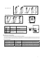
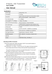
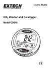
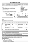
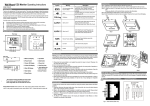
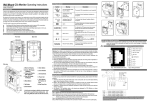
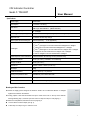
CO2 Indicator/Controller Model #: TON-0007 User Manual Specifications Power supply 24VAC/VDC Consumption 1.5 W Max ; 0.8 W avg CO2 sensor Infrared Sensor with lifetime of 15 years ABC Logic Self Calibration (default: effective) CO2 measuring range 0~2,000ppm Accuracy@25 (77 ),2000ppm ±40ppm + 3% of reading or ±75ppm (whichever is greater) Response time <2 minutes for 90% step change Warm up time for each turning-on 2 hours (first time) 2 min (operation) 1st green light on as CO2 measurement≤600ppm 1st and 2nd green lights on as CO2 measurement>600ppm and≤800ppm 6 LED lights 1st yellow light on as CO2 measurement>800ppm and≤1,200ppm 1st and 2nd yellow lights on as CO2 measurement>1,200ppm and≤1,400ppm 1st red light on as CO2 measurement>1,400ppm and≤1,600ppm 1st and 2nd red lights on as CO2 measurement>1,600ppm On/Off output for control CO2 level <240VAC/30VDC 3A switching current (resistance load), Operation conditions 0~50℃(32~122℉); 0~95%RH, non condensing Storage conditions 0~50℃(32~122℉); Dimensions 100mm×80mm×28mm (H X W X D) Net weight 180g Installment standard 65mm×65mm (2”×4”) wire box Housing and protection class PC/ABS fire proof material with IP30 Standard approval CE-Approval Version TSM-CO2-1A1R-ST02_65 (SE) Mounting and Wire Connection Notice the supply power voltage of the detector: 24VAC. Do not install the detector on voltages higher than marked on the detector. Firstly, prepare a flat head screwdriver and put it inside of the hole on the top of the detector housing following step 1, and then open the cover from step 2 to step 4 in next page fig.1. Mount the wall plate first, dimensions see next page fig. 2. Connect wires to terminal strips, (see fig. 3). Follow step 5 to step7 in fig. 4 to close the cover. 1 Fig.1 open the cover 1 4 3 2 Fig.4 close the cover Fig.2 wall plate 28.00 3.00 55.00 4.50 8.00 45.00 6 5 7 60.00 jump selection Fig.3 wiring diagram J6 J5 J6 J5 400ppm Connection Function Electrical Data J6 J5 1200ppm J6J5 800ppm J6 J5 1600ppm Terminal 1 G+ Power (+) 24VAC/VDC + 2 G0 Power ground (-) 24VAC/VDC 4 Ventilator 5 Common Relay output Common ON Line Voltage <240VAC/30VDC 3A switching 24VAC Transformer 1 2 4 5 current (resistance load) Select CO2 level to Control the Relay The CO2 level for control the relay turning on has been set to 1200ppm. If you need to change the CO2 level, open the cover after switch off, you may see two jumpers (J4 and J5) on the top of the circuit board and under the CO2 module. Take off the CO2 module, you can select the CO2 level to control the relay on /off by jumpers as below table. Jumper CO2 level Relay turns on /turns off J4-disconnect; J5-disconnect 800ppm CO2>900ppm,the relay on; CO2 <700ppm,the relay off J4-connect; J5-disconnect 1000ppm CO2>1100ppm, the relay on; CO2 <900ppm, the relay off J4-disconnect; J5-connect 1200ppm (default) CO2>1300ppm, the relay on; CO2 <1100ppm, the relay off J4-connect; J5-connect 1400ppm CO2>1500ppm, the relay on; CO2 <1300ppm, the relay off 2 Important Instructions: 1. Don’t shake or hit the CO2 unit too much in shipment or in mounting to protect the internal infrared CO2 sensor from any damage and excursion of infrared receiver. 2. When open the cover of the CO2 unit, you'll see one PCB board mounted over another bigger PCB board. This upper small PCB board is loaded with CO2 sensor. Don’t uninstall the CO2 module without instruction from our engineers, in order not to cause any damage to the CO2 sensor. Please note: the pins on the CO2 module which connect with the bigger PCB board have direction. Wrong connection will cause the CO2 module and processor damaged. 3