1
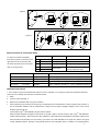
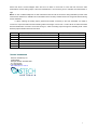
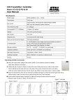
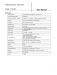
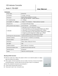
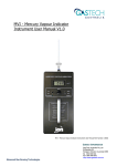
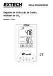
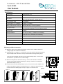
H-GuardTM CO2 Transmitter
Part #: 65-9080
User Manual
Specifications
Power supply
24VAC/24VDC±10%
Consumption
1.0 W Max
Carbon Dioxide: Non-Dispersive Infrared Detector (NDIR)
Gas sensor
ABC Logic Self Calibration (default: effective)
CO2 measuring range
0~2,000ppm
Accuracy@25℃(77℉),2000ppm
±40ppm +3% reading
Warm up time for each turning-on
48 hours (first time), 2 minutes (operation)
<240VAC/30VDC 2A switching current (resistance load),
Dry contact output
Four CO2 levels selectable to control the relay by jumpers
Analog output
4~20mA
Storage conditions
-40~70℃(-40~158℉) , 0~95%RH, non condensing
Operation conditions
0~50℃(32~122℉); 0~95%RH, non condensing
Net weight/ Dimensions
180g/100mm(H)×80mm(W)×24mm(D)
Installment standard
65mm×65mm(2”×4”) wire box, or hang on a nail
Approval
CE
Version
F2000TSM-CO2-88_1A1R-9900_61
Mounting and Wire Connection
u Notice the supply power voltage of the detector: 24VAC. Do not install the detector on
voltages higher than marked on the detector.
u Following step 1 to 4 in figure. 1 to remove the cover. First, prepare a flat head screwdriver
and put it deep inside of the hole on the top of the transmitter housing following step 1.
Then slant the screwdriver and open the cover gently following step 2. Do not mount it
near diffuser or any steam source, in direct sunlight.
2 8.0 0
3. 00
5 5.00
u Mount the wall plate first, dimensions see fig. 2. there are two dimensions available.
4 .50
If there is mounting box, please follow step 5 to 8 in fig. 3; if there’s no mounting box,
8.00
please follow step 5 to 8 in fig. 4.
4 5.0 0
u Connect wires to terminal strips (see figure 5), or you can put in the power adaptor to the
socket of the indicator instead of connecting terminal 1, 2. make sure wiring connection
60.0 0
correct and secure. Following step 4 to step 1 in figure 1 to close the cover.
Figure.2
Figure.5
Figure.1
<240VAC/30VDC/2A
L1
L2
Controled
device
4-20mA
CO2
mA
Common
Line
Voltage
1
2
3
Figure.3
4
Transformer
24VAC
Transformer
1 2 3
4 5
1
Figure.3
开/关/ 自动
IAQ lndicator/Controller
6
8
5
7
Figure.4
1mm
2
6
5
8
7
Select CO2 level to control the Relay
To open the controller’s faceplate,
Connection Terminal
Function
Electrical Data
there are 2 jumpers (J4 and J5) on the
1
G+
Power (+)
24VAC/24VDC +
right bottom of the circuit board. We
2
G0
Power ground (-)
24VAC/24VDC
can select the CO2 level to control the
3
OUT
Analog output (+)
4~20mA =0~2000ppm (CO2)
relay on /off by jumpers.
4
ventilator
5
Common
Relay output
<240VAC/30VDC 2A switching
current (resistance load)
Jumper
CO2 level
The relay turns on /turns off
J4-disconnect; J5-disconnect
800ppm
CO2>800ppm,the relay on;
J4-connect;
1000ppm
CO2>1,000ppm, the relay on; CO2 <900ppm,the relay off
J5-disconnect
J4-disconnect; J5-connect
1200ppm
J4-connect;
1400ppm
J5-connect
(default)
CO2 <700ppm,the relay off
CO2>1,200ppm, the relay on; CO2 <1,100ppm,the relay off
CO2>1,400ppm, the relay on; CO2 <1,300ppm,the relay off
Important Instructions
1. Don’t shake or hit the CO2 indicator/controller too much in shipment or in mounting to protect the internal infrared CO2
sensor from any damage and excursion of infrared receiver.
2. When
a.
First use CO2 transmitter, or
b.
Reuse CO2 transmitter after a long time unused or
c.
CO2 measurement is proved to be incorrect (by comparing with the measurement of other Tongdy’s CO2 products, or
put the transmitter outdoors and its measurement is away from the range of 350ppm~450ppm, which is the normal
ambient CO2 level range.)
Then let ABC LogicTM Self Calibration System work as follows:
TM
Keep the CO2 transmitter energized continuously for at least 2 days to let CO2 sensor’s ABC Logic
self-calibration
system operate properly. After more than 2 days’ calibration, if the measurement (indicated by the analog output) of the
CO2 transmitter still exceeds over the accuracy, you need to let it self-calibrated for a longer time. Here’s the typical
14-day calibration solution: During a 14-day period, place the CO2 transmitter twice in outdoors or unoccupied places
2
where CO2 level is around 400ppm. Each time let it be there for more than 4 hours and then check the CO2
measurement via the analog output. If the CO2 measurement is in its accuracy limit, it indicates the measurement is
right.
Notice: a. Use of cellular telephones or radio transceivers with two feet of the sensor during calibration process could
cause sensor interference, calibration errors and affect sensor accuracy. Please refrain from using these devices during
sensor calibration.
b. When checking the analog output, please avoid breath out directly to the CO2 transmitter. It’s better to
connect the output terminals with the Extending Wires with length of more than 1 meter. When the CO2 transmitter
becomes stable after more than 10 minutes turning-on, check the analog output through the extending wires. That’s
because people’s breath influences CO2 level.
J1
J2
J3
S1
S2
Jumpers setup for 4-20mA output (Default)
CONNECTED
DISCONNECTED
DISCONNECTED
UPPER POSITION
UPPER POSITION
Jumpers setup for 0-10 output
DISCONNECTED
DISCONNECTED
DISCONNECTED
LOWER POSITION
LOWER POSITION
Contact Information
GasTech Australia Pty Ltd
24 Baretta Rd
Wangara Western Australia 6065
Tel 1800 999 902
Fax 1800 999 903
http://www.gastech.com.au
3