1
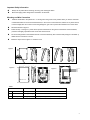
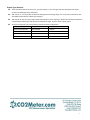
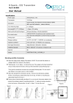
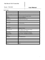
Wall Mount CO2 Transmitter Model:TON-0002 User Manual Specification Sensing Element Carbon Dioxide : Non-Dispersive Infrared Detector CO2 Measurement Range 0~5000ppm CO2 accuracy (@ 25 ±40ppm + 3% of reading or ±75ppm (whichever is greater) condition) Stability <2% of FS over lifetime (15 years) of sensor Calibration ABC Logic self-calibration Response time <2 minutes for 90% step change Renewed signal Every 2 sec Warm up time 2 hours (First time or using again after power off for a long time) 2 minutes (operation) Power supply 24VAC/VDC Consumption 1.8 W max. ; 1.2 W avg. Analog output 3 color backlit LCD 1x4~20mA output (default) or 1 x 0~10VDC (selectable by jumper) Green: CO2measurement≤ 1000ppm Yellow: 1000ppm< CO2measurement≤1400ppm Red: CO2measurement>1400ppm Work condition 0~50 (32~122 ); 0~95%RH, non condensing Storage condition 10~50 (50~122 ), 20~60%RH non condensing Weight 240g Dimensions 130mm×85mm×36.5mm Installment standard Wall mounting 65mm×65mm or 2”×4”wire box Housing PC/ABS fireproof plastic material, protection class: IP30 Certificate CE-Approval Version V. B030 1 Important Safety Information Always cut off power before mounting, removing, and cleaning the alarm. Notice the supply power voltage of the transmitter: 24 VAC/VDC. Mounting and Wire Connection Install the transmitter in the position of 1.2-1.3m high from the ground or the position where you need to collect the measurement data. Do not mount it behind the door, in the corner or near heat source, diffuser or any steam source, in direct sunlight; also do not mount it near the garbage bin, gas oven to prevent the evaluation error of the alarm. See the dimension in figure 2. Follow the step 1-3 in figure 1, power off and put the screwdriver into the groove at the bottom of the transmitter, press the lock lightly, separate the face cover from the back cover. Fix the mounting board on the wall with the bolt. Connect the electricity wire to the terminal (see figure 3 and table 1). Make sure the connection is correct. Follow the step 4 and 5 in figure 1 to close the cover. Figure 1 2 1 85.00 Figure 2 4 3 5 36.50 Figure 3 TONGDY CO2 T H 9.50 4.20 VOC's 130.00 84.00 60.00 60.00 24Vac/dc GND AN1 AN2 AN3 B RS-485 A AC/DC ON/OFF IAQ CO2 Transmitter 空气质量监测警示器 Table 1 Connection Terminal Function Electrical Data 1 G+ Power (+) 24VAC/24VDC + 2 G0 Power ground (-) 24VAC/24VDC 3 OUT3 (CO2) Analog output (+) 4~20mA(default) correspond to 0~5000ppm 2 Output Type Selection Power off first and remove the face cover, you’ll see Jumper J1~J3 on the upper left of the PCB board and Jumper S1~S6 in the middle right of the PCB board. With Jumper J1, you may be able to select the starting point of the analog output. J2 & J3 are just for manufacture test, with default of disconnection. Please don’t change it! With Jumper S1~S6, you may be able to select either voltage or current output type. Please note that jumper S5 & S6 are corresponding to CO2 output, while S3 & S4 for temperature output, and S1 & S2 for humidity output. Choose the output type you want by following instructions shown in table below Jumper S5~S6 Jumper J1 Analog output for CO2 Upper two pins blocked disconnected 0~10VDC Lower two pins blocked disconnected 0~20MA Upper two pins blocked Connected 2~10VDC Lower two pins blocked Connected 4~20MA (default) 3