1
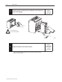
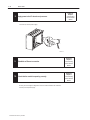
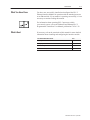
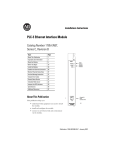
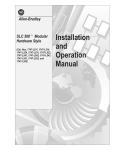
Allen-Bradley PLC-5 Ethernet Interface Module (Cat. No. 1785-ENET) User Manual Important User Information Because of the variety of uses for the products described in this publication, those responsible for the application and use of this control equipment must satisfy themselves that all necessary steps have been taken to assure that each application and use meets all performance and safety requirements, including any applicable laws, regulations, codes and standards. The illustrations, charts, sample programs and layout examples shown in this guide are intended solely for purposes of example. Since there are many variables and requirements associated with any particular installation, Allen-Bradley does not assume responsibility or liability (to include intellectual property liability) for actual use based upon the examples shown in this publication. Allen-Bradley publication SGI-1.1, Safety Guidelines for the Application, Installation, and Maintenance of Solid-State Control (available from your local Allen-Bradley office), describes some important differences between solid-state equipment and electromechanical devices that should be taken into consideration when applying products such as those described in this publication. Reproduction of the contents of this copyrighted publication, in whole or in part, without written permission of Allen-Bradley Company, Inc., is prohibited. Throughout this manual we use notes to make you aware of safety considerations: ! ATTENTION: Identifies information about practices or circumstances that can lead to personal injury or death, property damage or economic loss. Attention statements help you to: • identify a hazard • avoid the hazard • recognize the consequences Important: Identifies information that is critical for successful application and understanding of the product. ControlNet is a trademark; PLC is a registered trademark of Allen-Bradley Company, Inc. Table of Contents Quick Start Chapter 1 Installing and Configuring the Interface Module . . . . . . . . . . . . . . . What You Have Done . . . . . . . . . . . . . . . . . . . . . . . . . . . . . . . . . . What’s Next . . . . . . . . . . . . . . . . . . . . . . . . . . . . . . . . . . . . . . . . Installing the Interface Module Chapter 2 Using This Chapter . . . . . . . . . . . . . . . . . . . . . . . . . . . . . . . . . . . Before You Begin . . . . . . . . . . . . . . . . . . . . . . . . . . . . . . . . . . . . . Necessary Equipment . . . . . . . . . . . . . . . . . . . . . . . . . . . . . . . . . Preventing Electrostatic Discharge Damage (ESD) . . . . . . . . . . . . . Complying with European Union Directives . . . . . . . . . . . . . . . . . . EMC Directive . . . . . . . . . . . . . . . . . . . . . . . . . . . . . . . . . . . . . Low Voltage Directive . . . . . . . . . . . . . . . . . . . . . . . . . . . . . . . . Installing the Interface Module . . . . . . . . . . . . . . . . . . . . . . . . . . . Attach the Connector Header to the Processor . . . . . . . . . . . . . . Connect the Interface Module to the Processor . . . . . . . . . . . . . Install the Processor/Interface Module into the Chassis . . . . . . . . Removing the Interface Module . . . . . . . . . . . . . . . . . . . . . . . . . . . Configuring the Interface Module for Ethernet Communication 1–2 1–7 1–7 2–1 2–2 2–3 2–3 2–4 2–4 2–4 2–5 2–5 2–6 2–7 2–8 Chapter 3 Using This Chapter . . . . . . . . . . . . . . . . . . . . . . . . . . . . . . . . . . . Before You Begin . . . . . . . . . . . . . . . . . . . . . . . . . . . . . . . . . . . . . Configuring Channel 3A . . . . . . . . . . . . . . . . . . . . . . . . . . . . . . . . Designate Channel 3A to Support the Interface Module . . . . . . . . Specify Ethernet-specific Information . . . . . . . . . . . . . . . . . . . . . Manually Entering Module Configuration Information . . . . . . . Dynamically Supplying Configuration Information using BOOTP Using the BOOTP Servers on the Utility Disk . . . . . . . . . . . . . . . . . Install the DOS/Windows BOOTP server disk . . . . . . . . . . . . . . . Edit the DOS/Windows BOOTP Configuration File . . . . . . . . . . . Run the Boot Server Utility . . . . . . . . . . . . . . . . . . . . . . . . . . . . Running the DOS-Based Utility . . . . . . . . . . . . . . . . . . . . . . . Running the Windows-Based Utility . . . . . . . . . . . . . . . . . . . . 3–1 3–1 3–2 3–2 3–3 3–3 3–5 3–6 3–6 3–7 3–9 3–9 3–10 Publication 1785-6.5.19–June 1996 ii Table of Contents Communicating Via the Interface Module Chapter 4 Module Specifications Appendix A Peformance Data Appendix B SNMP Management Information Base (MIB) II Data Groups Appendix C Status LED Error Codes Appendix D Publication 1785-6.5.19–June 1996 Using This Chapter . . . . . . . . . . . . . . . . . . . . . . . . . . . . . . . . . . . Applying Power to the Chassis . . . . . . . . . . . . . . . . . . . . . . . . . . . Monitoring the LEDs . . . . . . . . . . . . . . . . . . . . . . . . . . . . . . . . . . Establishing an Ethernet Connection . . . . . . . . . . . . . . . . . . . . . . . Monitoring Ethernet Status Data . . . . . . . . . . . . . . . . . . . . . . . . . . Using the Message Instruction . . . . . . . . . . . . . . . . . . . . . . . . . . . Interpreting Error Codes . . . . . . . . . . . . . . . . . . . . . . . . . . . . . . . . SNMP Support . . . . . . . . . . . . . . . . . . . . . . . . . . . . . . . . . . . . . . Saving and Restoring Programs . . . . . . . . . . . . . . . . . . . . . . . . . . 4–1 4–1 4–1 4–4 4–5 4–7 4–9 4–10 4–10 Preface Preface Read this preface to familiarize yourself with the rest of the manual. This preface covers the following topics: • who should use this manual • the purpose of this manual • Allen-Bradley support Who Should Use this Manual Use this manual if you are responsible for designing, installing, programming, or troubleshooting control systems that use Allen-Bradley programmable controllers or interface modules. You should have a basic understanding of PLC-5 programmable controller products and the following Ethernet-related topics: • TCP/IP protocol • Internet addressing If you do not have an understanding of these areas, contact your local Allen-Bradley representative for information on available training courses before using this product. Purpose of this Manual This manual: • tells you what equipment you must provide for installing the PLC-5 Ethernet Interface Module • helps you install and configure the interface module • helps you connect to an Ethernet link and communicate via the interface module Publication 1785-6.5.19–June 1996 P–2 Preface Contents of this Manual Chapter Title Contents Preface Describes the purpose, background, and scope of this manual. Also specifies the audience for whom this manual is intended. Quick Start Provides brief installation and configuration procedures for the advanced user. 2 Installing the Interface Module Explains and illustrates how to install and remove the interface module into and from the 1771 I/O chassis. Also specifies compliance with European Union Directives. 3 Configuring the Interface Module for Ethernet Communication 4 Communicating Via the Interface Module Describes how to establish an Ethernet connection and monitor status data. Also specifies how to use the MSG instruction over the Ethernet link. Appendix A Specifications Provides physical, electrical, and environmental specifications for the interface module. Appendix B Performance Data Provides measured performance data for the interface module. Appendix C SNMP Management Information Base (MIB) II Data Groups Describes the SNMP Management Information Base (MIB) II Data Groups. Appemdix D Status LED Error Codes Describes the status LED error codes. 1 Provides instructions for: • configuring channel 3A to support the interface module • assigning an IP address to the module • using the BOOTP servers on the utility disk Related Documentation For additional information regarding Allen-Bradley programmable controllers and related products, see the Enhanced and Ethernet PLC-5 Programmable Controllers User Manual, publication 1785-6.5.12. To obtain a copy, contact your local Allen-Bradley office or distributor. Publication 1785-6.5.19–June 1996 Preface Allen-Bradley Support P–3 Allen-Bradley offers support services worldwide, with over 75 Sales/Support Offices, 512 authorized Distributors and 260 authorized Systems Integrators located throughout the United States alone, plus Allen-Bradley representatives in every major country in the world. Local Product Support Contact your local Allen-Bradley representative for: • sales and order support • product technical training • warranty support • support service agreements Technical Product Assistance If you need technical assistance, call your local Allen-Bradley representative. Your Questions or Comments on this Manual If you find a problem with this manual, please notify us of it on the enclosed Publication Problem Report. If you have any suggestions for how this manual could be made more useful to you, please contact us at the address below: Technical Communication Allen-Bradley Comapny 1 Allen-Bradley Drive Mayfield Heights, Ohio 44124 Publication 1785-6.5.19–June 1996 Chapter 1 Quick Start 1 Status indicator Transmit indicator This chapter can help you get started quickly using the PLC-5 Ethernet Interface Module. We base the procedures here on the assumption that you have an understanding of: • PLC-5 products • TCP/IP protocol • Internet addressing Because this is a quick start guide for experienced users, this chapter does not contain detailed explanations about the procedures listed. It does, however, reference other chapters in this book where you can get more information. If you have any questions or are unfamiliar with the terms used or concepts presented in the procedural steps, always read the referenced chapters and other recommended documentation before trying to apply the information. External transceiver fuse This chapter: • tells you what equipment you must provide for installing the Ethernet interface module • helps you install and configure the module • helps you connect to an Ethernet link and communicate via the interface module Channel 3A: 15-pin AUI connector port 20611–M Publication 1795-6.5.19–June 1996 1–2 Quick Start 1 Installing and Configuring the Interface Module 1. Quantity 2. ✔ Check the contents of your shipment. Description 1 PLC-5 Ethernet Interface Module (1785-ENET) 1 Connector kitit containing 1 PLC-5 58-pin connector header 1 Industrial Automation Wiring and Grounding Guidelines, publication 1770-4.1 1 PLC-5 Ethernet Interface Module User Manual, publication 1785-6.5.19 1 BOOTP Utility Diskette Locate and have ready all equipment and tools necessary for installation. I/O Chassis (1771-A1B/B, -A2B/B, -A3/B or -A4B/B) ESD Grounding Wrist Strap Publication 1795-6.5.19–June 1996 ✔ PLC-5 Processor Supported processors and current firmware (see page 2-1) phillips screwdriver Any external or internal Allen-Bradley power supply Quick Start 1 3. 1–3 Reference Chapter 2 Installing the Interface Module Attach the connector header to the processor. connector header Attach the interface module to this end. Push the exposed pins into the holes on the PLC-5 processor. ! Important: 4. Wear a grounding wrist strap to guard against ESD. 19379 Make sure you carefully align the pins and holes before you press the connector header into the processor. If you improperly align them, you will bend the connector header pins when you press them together. Do not use excessive force on the connector header when seating it into the processor. You do not need to key the connector. Reference Chapter 2 Installing the Interface Module Use the captive screws to connect the interface module to the processor. Front of the interface module Front of the PLC-5 processor Installed connector header 20597–M Publication 1795-6.5.19–June 1996 1–4 Quick Start 1 5. ! Install the interface module/processor combination in the left-most slot of the 1771 I/O chassis. Reference Chapter 2 Installing the Interface Module Be sure power to the 1771 I/O chassis is OFF. 20582–M 6. Assign an IP address to the interface module. Contact your Ethernet network administrator or the international Network Information Center for a unique IP address. Publication 1795-6.5.19–June 1996 Reference Chapter 3 Configuring the Interface Module for Ethernet Communication Quick Start 1 7. Reference Chapter 3 Configuring the Interface Module for Ethernet Communication Configure channel 3A for Ethernet communication. a. 1–5 Be sure channel 3A is designated as the channel supporting the 1785-ENET module. • If you are using 6200 Programming Software, you must have revision 5.2 or later to configure Channel 3A for Ethernet communication. The PLC-5 processor must also contain the proper firmware revision. See page 2-1 for information about firmware revision levels. • If you are configuring online and the interface module is attached to the processor, channel 3A will automatically support the interface module. • If you are configuring offline, follow the steps listed in your programming software documentation. b. Specify Ethernet-specific configuration information (including the IP address) using any one of the following methods: • manually configure channel 3A using your programming software package. • use the BOOTP server on the utility disk that came with your interface module (see page 3–5 for information about installing and using this disk). • use a BOOTP server already on your network (see your Ethernet network administrator for assistance). Important: Be sure to assign a diagnostics file to store all status information for channel 3A. Cursor to the diagnostics file field on the channel configuration screen, type an unused integer file number (10–999), and press [Enter]. The system creates an integer file 44 words long. Publication 1795-6.5.19–June 1996 1–6 Quick Start 1 8. Reference Chapter 4 Communicating Via the Interface Module Apply power to the I/O chassis and processor. Turn on the I/O chassis power supply. 20634–M 9. 10. Establish an Ethernet connection. Reference Chapter 4 Communicating Via the Interface Module Check that the module is operating correctly. Reference Chapter 4 Communicating Via the Interface Module Be sure you have assigned a diagnostics file to store status information for channel 3A. See step 7 on the previous page. Publication 1795-6.5.19–June 1996 Quick Start 1 What You Have Done 1–7 You have now successfully installed and configured the PLC-5 Ethernet Interface Module for operation with the attached processor on an Ethernet link. If your module is operating successfully, it is not necessary to continue reading this manual. For information about operating PLC-5 processors within your control system, refer to the Enhanced and Ethernet PLC-5 Programmable Controllers User Manual, publication 1785-6.5.12. What’s Next If necessary, refer to the remainder of this manual for more detailed information about installing and configuring the interface module. For detailed information about See Installing the interface module Chapter 2 Configuring the interface module for Ethernet communication Chapter 3 Communicating over Ethernet via the interface module Chapter 4 Interface module specifications Appendix A Publication 1795-6.5.19–June 1996 Chapter 2 Installing the Interface Module Using This Chapter Read this chapter to:2 • connect your Ethernet interface module to a PLC-5 processor • install the processor/interface module combination in a 1771 I/O chassis. For information about: Status indicator Transmit indicator See page: Checking the 1785-ENET package before you begin 2–2 Equipment you must provide 2–3 Preventing Electrostatic Discharge Damage (ESD) 2–3 Complying with the European Union Directive 2–4 Installing the Ethernet interface module 2–5 Removing the Ethernet interface module 2–8 The PLC-5 Ethernet Interface Module is a single-slot module that attaches to the side of any enhanced PLC-5 Series B or later processor to provide Ethernet connectivity for the attached processor. When used with The interface module provides Enhanced PLC-5 processor Ethernet connectivity without sacrificing DH+/RIO ports ControlNet PLC-5 processor Ethernet connectivity Ethernet PLC-5 processor the ability to operate dual Ethernet links Use the interface module with a programming software package. If you use 6200 Programming Software, you must use release 5.2 and later, and any of the following current firmware revisions for PLC-5 processors: External transceiver fuse Processor Model Enhanced Channel 3A: 15-pin AUI connector port ControlNet Control et Enhanced PLC-5/40 1785–ENET interface module Ethernet 20613–M Series Revision PLC-5/11, -5/20, -5/26, -5/30, -5/40, -5/40L, -5/46, -5/46L, -5/60, -5/60L, -5/80, -5/86 D B PLC-5/V30, -5/V40, -5/V40L, -5/V80 C K PLC-5/40, -5/40L, -5/46, -5/46L, -5/60, -5/60L B L PLC-5/30 A L PLC-5/11, -5/20, -5/26 A K PLC-5/20C, -5/40C PLC-5/20C -5/40C, -5/60C -5/60C, -5/80C D B PLC-5/20C, -5/40C C K PLC-5/20E, -5/40E PLC-5/20E -5/40E, -5/80E D B C K Publication 1795-6.5.19–June 1996 2–2 Installing the Interface Module Before You Begin Before installing your Ethernet interface module: 1. Check your Ethernet interface module package. 2. Make certain that you have the following: Quantity Description 1 PLC-5 Ethernet Interface Module (1785-ENET) 1 Connector kitit containing 1 PLC-5 58-pin connector header 1 Industrial Automation Wiring and Grounding Guidelines, publication 1770-4.1 1 PLC-5 Ethernet Interface Module User Manual, publication 1785-6.5.19 1 BOOTP Utility Diskette If any items are missing or incorrect, contact your local Allen-Bradley sales office or distributor. 3. Locate and record the Ethernet hardware address. Allen-Bradley assigns each PLC-5 Ethernet interface module an Ethernet hardware address at the factory. Look for this address either: • in the back, upper corner of your module • in the channel 3A configuration screen of your PLC-5 programming software Ethernet hardware address label 19915 Publication 1795-6.5.19–June 1996 Installing the Interface Module Necessary Equipment Locate and have ready all the tools and equipment necessary for installation: I/O Chassis (1771-A1B/B, -A2B/B, -A3/B or -A4B/B) ESD Grounding Wrist Strap Preventing Electrostatic Discharge Damage (ESD) 2–3 PLC-5 Processor Supported processors and current firmware (see page 2-1) phillips screwdriver Any external or internal Allen-Bradley power supply The Ethernet interface module is shipped in a static-shielded container to guard against electrostatic discharge (ESD). ESD can damage integrated circuits or semiconductors in the module if you touch the backplane connector pins. Avoid electrostatic damage by observing the following precautions: • Remain in contact with an approved ground point while handling Wrist strap the module (by wearing a properly grounded wrist strap). • Do not touch the backplane connector or connector pins. • When not in use, keep the module in its static-shielded container. Publication 1795-6.5.19–June 1996 2–4 Installing the Interface Module Complying with European Union Directives ÏÏ ÏÏ Ï ÏÏ ÏÏ Ï ÏÏ ÏÏ Ï ÏÏ ÏÏ Ï If this product has the CE mark it is approved for installation within the European Union and EEA regions. It has been designed and tested to meet the following directives. EMC Directive This product is tested to meet Council Directive 89/336/EEC Electromagnetic Compatibility (EMC) and the following standards, in whole or in part, documented in a technical construction file: • EN 50081-2 EMC – Generic Emission Standard, Part 2 – Industrial Environment • EN 50082-2 EMC – Generic Immunity Standard, Part 2 – Industrial Environment This product is intended for use in an industrial environment. Low Voltage Directive This product is tested to meet Council Directive 73/23/EEC Low Voltage, by applying the safety requirements of EN 61131–2 Programmable Controllers, Part 2 – Equipment Requirements and Tests. For specific information that this EN requires, see the appropriate sections in this publication, as well as the following Allen-Bradley publications: • Industrial Automation Wiring and Grounding Guidelines (for noise immunity), publication 1770-4.1 • Guidelines for Handling Lithium Batteries, publication AG-5.4 • Automation Systems Catalog, publication B111 • Enhanced and Ethernet PLC-5 Programmable Controllers User Manual, publication 1785-6.5.12 Publication 1795-6.5.19–June 1996 Installing the Interface Module Installing the Interface Module 2–5 To install the PLC-5 Ethernet Interface Module, you must: • attach the connector header to the processor • attach adhesive washers to the processor • connect the interface module to the processor • install the combination into the chassis ! ATTENTION: If your power supply is already installed in the chassis, be sure the chassis power supply is turned OFF before you begin the installation procedures. Do not attempt to install the interface with chassis power ON. Installing the module with chassis power ON will damage the module. Attach the Connector Header to the Processor If you have not already done so, attach a grounding wrist strap to your wrist. Then follow these steps to attach the connector header to the processor: 1. Locate the PLC-5 processor 2. connector header port. Push the exposed pins into the holes on the PLC-5 processor. the interface module to 3. Attach this end of the connector header. 20596–M Important: Make sure you carefully align the pins and holes before you press the connector header into the processor. If you improperly align them, you will bend the connector header pins when you press them together. Do not use excessive force on the connector header when seating it into the processor. You do not need to key the connector. Publication 1795-6.5.19–June 1996 2–6 Installing the Interface Module Connect the Interface Module to the Processor Lay the processor on a flat surface and follow these steps to connect the interface module to the processor: 1. Align the pins and holesof the interface module to those on the connector header. Front of the interface module 2. Press the interface module into the connector header. 3. Tighten the screws. Front of the PLC-5 processor Installed connector header 20597–M Important: Publication 1795-6.5.19–June 1996 Make sure you carefully align the pins and holes before you press the interface module into the connector header. If you improperly align them, you will bend the connector header pins. Installing the Interface Module 2–7 Install the Processor/Interface Module into the Chassis To install the attached modules into the 1771 I/O chassis, follow these steps: 1. Verify that power to the 1771 I/O chassis is OFF. 2. Raise the locking bar. ! Remember to wear a grounding wrist strap to guard against ESD. 3. Insert the module combination into the 1771 I/O chassis in the left-most slots and slide along the the card guides. 4. Lower the locking bar into place over the modules. 20615-M Publication 1795-6.5.19–June 1996 2–8 Installing the Interface Module Removing the Interface Module To remove the interface module from its installed position, follow the instructions below. 1. Remove power to the 1771 I/O chassis. 2. Lift the locking bar up and away from the processor and interface module. Ejector tabs ! Remember to wear a grounding wrist strap to guard against ESD. 3. Lift the ejector tabs on the front of each module simultaneously and remove the connected modules. 4. Loosen the four screws on the side of the interface module. PLC-5 processor Ethernet Interface Module 20599–M 5. Separate the interface module from the processor by placing your finger tips between the two modules. Pull directly and evenly upward. ! Publication 1795-6.5.19–June 1996 Do not pry the interface module away from the processor by pulling on one corner or side. You will bend the connector header’s pins. Chapter 3 Configuring the Interface Module for Ethernet Communication3 Using This Chapter For information about See page Before you begin 3–1 Configuring Channel 3A 3–2 Designate channel 3A to support 1785-ENET module 3–2 Specify Ethernet-specific information 3–2 Using the BOOTP utility disk Before You Begin 3–5 Before configuring channel 3A for Ethernet communication, be sure to: • know the Ethernet hardware address (see page 2–2) • assign an IP address to the module Because the PLC-5 Ethernet Interface Module uses the TCP/IP protocol, each Ethernet hardware address on the network requires a unique IP address. If your interface module is connected to You must assign a unique IP address for each Ethernet hardware address. Then you must assign two (2) IP addresses: an Ethernet PLC-5 processor • one for the processor • one for the interface module an Enhanced PLC-5 processor one (1) IP address for the interface module a ControlNet PLC-5 processor one (1 IP address) for the interface module The IP address is software-configurable using either the BOOTP protocol or your programming software package. See the “Manually Entering Module Configuration Information” section on page 3–3 or the “Dynamically Supplying Configuration Information using BOOTP” section on page 3–4. If you are familiar with Internet addressing, contact your network administrator or Network Solutions Inc. (the InterNIC) for a unique IP address to assign to your Ethernet interface module. You can reach the InterNIC by dialing (703) 742–4777 or by email at [email protected]. Publication 1795-6.5.19–June 1996 3–2 Configuring the Interface Module for Ethernet Communication3 If you are unfamiliar with Internet addressing, refer to: Comer, Douglas E; Internetworking with TCP-IP, Volume 1: Principles, Protocols and Architecture; Englewood Cliffs, N.J.: Prentice-Hall, 1995. Use unique addresses that follow the basic TCP/IP guidelines. Configuring Channel 3A Once you know the unique IP address that you will assign to the PLC-5 Ethernet Interface Module, you must configure channel 3A so your network recognizes the module. To configure channel 3A, use your programming software package to: • designate channel 3A as the channel that supports the PLC-5 Ethernet Interface Module if you are configuring offline (if you are configuring online, designation is automatic) Important: To configure the 1785-ENET module online, it must be attached to the PLC-5 processor. • specify Ethernet-specific information Designate Channel 3A to Support the Interface Module Use your programming software package to designate Channel 3A to support the interface module. Specify Ethernet-specific Information Specify Ethernet-specific information for the interface module by either: • manually entering module configuration information using the screens within your programming software package • dynamically supplying module configuration information using a BOOTP utility If you Then have a BOOTP server on your network use that server and edit the BOOTPTAB file to include the interface module; or use manual configuration with PLC-5 programming software do not have a BOOTP server on your network dynamically configure the module using the BOOTP server on the utility disk that came with your interface module (edit the BOOTPTAB file to include the interface module); or use manual configuration with PLC-5 programming software Publication 1795-6.5.19–June 1996 Configuring the Interface Module for Ethernet Communication3 BOOTP enabled is the factory default. You must disable BOOTP for your manual entries to take effect upon accepting edits. 3–3 Manually Entering Module Configuration Information To manually enter module configuration information for channel 3A, follow the steps specified in your programming software documentation. Enter configuration information in the appropriate fields. See Table 3.A. Table 3.A Ethernet Channel 3A Configuration Fields This field: Specifies: Configure by doing the following: Diagnostics file The file containing the channel’s status information Cursor to the field, type an unused integer file number (10–999), and press [Enter]. The system creates an integer file 44 words long. ATTENTION: Do not assign a diagnostic file number that is the I/O status file you assigned to another communication channel or any other used file. Unpredictable machine action can result. Important: You must define a diagnostics file for a channel configured for anything but unused (even if you are not using the channel) if you want status information for that channel. Ethernet Address The interface module’s Ethernet hardware address Assigned by Allen-Bradley and cannot be changed. Displayed as a set of 6 bytes (in hex), separated by colons. Display only. IP Address The interface module’s Internet address Cursor to the field, and enter an address in this form: a.b.c.d Where: a, b, c, d are between 1-254 (decimal) You must specify the IP address to have the interface module connect to the TCP/IP network. Do not use 0 or 255 as a, b, c, or d in the IP address. BOOTP Enable Whether BOOTP is enabled Cursor to the field and specify No (for manual configuration). Before you disable BOOTP, make sure you have an IP address specified. With BOOTP set to No, the interface module uses the parameters that you specify locally. To enable BOOTP, see the “Dynamically Configuring Channel 3A Using BOOTP” section on page 3–4. MSG Conn Timeout MSG Reply Timeout Inactivity Timeout The number of milliseconds allowed for an MSG instruction to establish a connection with the destination node Cursor to the field, and enter a timeout period in milliseconds. (The interface module rounds to the nearest 250 ms.) The valid range for a timeout period is 0-65,535 ms. The number of milliseconds the Ethernet interface waits for a reply to a command it initiated (through an MSG instruction) Cursor to the field, and enter a timeout period in milliseconds. (The interface module rounds to the nearest 250 ms.) The valid range for a timeout period is 0-65,535 ms. The number of minutes of inactivity before the connection is closed Cursor to the field, and enter a timeout period in minutes. The valid range for a timeout period is 0-65,535 minutes. The default is 15,000 ms. The default is 3,000 ms. The default is 30 minutes. Advanced functions Broadcast Address The broadcast address to which the processor should respond Subnet Mask The processor’s subnet mask See the Enhanced and Ethernet PLC-5 Programmable Controllers User Manual, (used when network has subnets) publication 1785-6.5.12 for information about how to configure these advanced Ethernet functions. The IP address of the gateway that provides a connection to another IP network Gateway Address After entering the channel 3A configuration information, either accept edits or access status information about channel 3A. Be sure you have assigned a diagnostics file in which to store channel status information. Publication 1795-6.5.19–June 1996 3–4 Configuring the Interface Module for Ethernet Communication3 Dynamically Supplying Configuration Information using BOOTP BOOTP is a protocol that will supply the interface module with configuration information at power-up. BOOTP lets you dynamically assign IP addresses to devices on the Ethernet link. To use BOOTP, a BOOTP server must exist on the local Ethernet subnet. The server is a computer (either a personal computer, VAX, or UNIX system) that has BOOTP-server software installed and reads a text file containing network information for individual nodes on the network. If you do not have BOOTP server capabilities on your network and you want to dynamically configure Channel 3A, use either the DOS or Windows BOOTP servers supplied on the BOOTP utility disk that shipped with your interface module. You must have FTP’s PC/TCP software running on your PC to operate the DOS utility or a standard winsock.dll to operate the Windows utility. To enable BOOTP, follow the steps specified in your programming software documentation to specify Ethernet configuration information. Refer to Table 3.A on page 3–3 for field descriptions. Publication 1795-6.5.19–June 1996 Configuring the Interface Module for Ethernet Communication3 Using the BOOTP Servers on the Utility Disk 3–5 The disk you received with your interface module contains DOS-based and Windows-based BOOTP servers. Both provide BOOTP services for PLC-5 Ethernet Interface Modules and PLC-5 Ethernet processors. Regardless of the platform you are using, you must: • install the boot-server utility disk • edit the boot-server configuration file • run one of the BOOTP servers on the utility disk Important: Do not use the BOOTP utility disk if you already have RSLinx or INTERCHANGE software installed. Instead, use the BOOTP server capabilities that came with your RSLinx or INTERCHANGE software. Install the DOS/Windows BOOTP server disk To install the DOS BOOTP server: 1. Put the utility disk that came with your interface module in your disk drive. 2. Make the floppy drive the default by typing “a:”, where “a” is the drive letter. 3. Type install c:, and press [Enter]. 4. The software is installed in C:\ABIC\BIN. Put this directory in the path statement of your AUTOEXEC.BAT file. Publication 1795-6.5.19–June 1996 3–6 Configuring the Interface Module for Ethernet Communication3 Edit the DOS/Windows BOOTP Configuration File The boot-server configuration file, BOOTPTAB, is located in the C:\ABIC\BIN directory. This file contains the information needed to boot the Ethernet interface module. Important: Be sure you know the Ethernet hardware address of the module. You will enter it in this file. You must edit the BOOTPTAB file, which is an ASCII text file, to include the name, IP address, and hardware address for each Ethernet interface module you want the server to boot. To edit this file: 1. Open the BOOTPTAB file using a text editor. See an example of a BOOTPTAB file on the following page. – The file contains lines that look like this: #Default string for each type of Ethernet client defaults5E: ht=1:vm=rfc1048 – These are the default parameters for Ethernet PLC-5 interface modules and must always precede the client lines in the BOOTPTAB file. – The file also contains a line that looks like this: sidecar: tc=defaults5E:ip=aa.bb.cc.dd:ha=0000BC03xxyy Important: Use this line as the configuration template for Ethernet devices. 2. Make one copy of the Ethernet device template for every PLC-5 Ethernet Interface Module in your system (i.e. one line per module). 3. Edit each copy of the template as follows: The term “sidecar” in this template is a logical name used for identification in this file only. It is not associated with the stored processor name. a. Replace sidecar with the name you assigned the Ethernet interface module. Use only letters and numbers; do not use underscores. b. Replace aa.bb.cc.dd with the IP address to be assigned to the interface module. c. Replace xxyy with the last four digits of the Ethernet hardware address. Use only valid hexadecimal digits (0-9, A-F); do not use the hyphens or colons that separate the numbers. (You will find the hardware address on a label affixed to the printed circuit board of the Ethernet interface module.) 4. Save, close, and make a backup copy of this file. Publication 1795-6.5.19–June 1996 Configuring the Interface Module for Ethernet Communication3 3–7 Example In this example there are three PLC-5 processors (two enhanced processors and one Ethernet processor) with attached 1785-ENET interface modules and an HP 9000 workstation. The names and hardware addresses are device specific: Device PLC-5/20S PLC-5/20S PLC-5/40E PLC-5/40S Name device1 device2 device3 device4 IP Address 12.34.56.1 12.34.56.2 12.34.56.3 12.34.56.4 Hardware Address 00–00–BC–03–12–34 00–00–BC–03–56–78 00–00–BC–1C–90–12 00–00–BC–03–88–27 802.3/Ethernet (TCP/IP) BOOTP server HP 9000 (HP-UNIX) computer) PLC-5/20S (enhanced PLC-5 processor with 1785-ENET) device1 PLC-5/20S (enhanced PLC-5 processor with 1785-ENET) device2 PLC-5/40E with attached 1785-ENET module (for use of additional communication port) devices 3 and 4 Based on this configuration, the BOOTPTAB file would look like this: # # # # # # # Legend: gw –– gateways ha –– hardware address ht –– hardware type① ip –– host IP address sm –– subnet mask vm –– BOOTP vendor extensions format② tc –– template host #Default string for each type of Ethernet client defaults5E: ht=1:vm=rfc1048 #Entries device1: device2: device4: for 1785-ENET modules: tc=defaults5E:ip=12.34.56.1:ha=0000BC031234 tc=defaults5E:ip=12.34.56.2:ha=0000BC035678 tc=defaults5E:ip=12.34.56.4:ha=0000BC038827 #Entries for Ethernet PLC-5 processors: device3: tc=defaults5E:ip=12.34.56.3:ha=0000BC1C9012 ① 1 = 10MB Ethernet ② Use rfc1048 Publication 1795-6.5.19–June 1996 3–8 Configuring the Interface Module for Ethernet Communication3 Run the Boot Server Utility You can run either the DOS-based utility or the Windows-based BOOTP utility, but not both. If you’re using then invoke this executable DOS DTLBOOTD.EXE DOS command line (specify optional parameters if necessary) 3–8 Windows DTLBOOTW.EXE Windows File Manager 3–9 from the If you are invoking this executable you also need DTLBOOTD.EXE FTP’s TCP/IP software DTLBOOTW.EXE a standard winsock.dll See page Both utilities are located in the C:\RSI\BIN directory and use the information contained in the BOOTPTAB file. " Be sure to place the BOOTPTAB file in the directory from which you are running the BOOTP utility. If this file is not in that directory, the utility will try to find the file in the directory specified by the environment variable ABIC_CONFIG. Running the DOS-Based Utility To run the DOS-based boot-server utility, DTLBOOTD.EXE, follow these steps: 1. At the DOS prompt, type: DTLBOOTD [–d] [–t <timeout>] [–b <numboots>] [–f <numfiles>] [configfile] [logfile] Parameter Description -d –t <timeout> –b <numboots> –f <numfiles> configfile provide additional information for debug purposes. exit after <timeout> seconds of inactivity. exit after answering <numboots> number of boot requests. exit after answering <numfiles> number of file requests. name of the boot server configuration file to use. The default configuration file is %ABIC_CONFIG%\BOOTPTAB. name of the log file to use. The default log file is logfile %ABIC_CONFIG%\DTLBOOTD.LOG. To exit, press [Ctrl-C] or [Esc]. Publication 1795-6.5.19–June 1996 Once you invoke the utility, it will run until the specified exit parameter is satisfied. You can exit at any time by pressing [Ctrl-C] or [Esc]. Configuring the Interface Module for Ethernet Communication3 3–9 2. Apply power to all chassis containing Ethernet PLC-5 processors and interface modules. At power-up, each PLC-5 Ethernet Interface Module broadcasts a BOOTP request if BOOTP was enabled at the Channel 3A Configuration screen. The module’s hardware address is contained in the BOOTP request. The Ethernet boot server compares the hardware address with those listed in BOOTPTAB and responds by sending the corresponding IP address and other configuration data to the interface module via a BOOTP reply. Running the Windows-Based Utility To run the Windows-based boot-server utility, DTLBOOTW.EXE, follow these steps: 1. Start Microsoft Windows 3.x, if it is not already running. 2. Open the File Manager window, if it is not already open. 3. Choose File on the menu bar and select Run from the menu. 4. In the dialog box, type C:\ABIC\BIN\DTLBOOTW; then, choose OK or press [Enter]. Once you invoke the utility, it will run until you terminate it by closing the DTLBOOTW.EXE window. 5. Apply power to all chassis containing Ethernet PLC-5 processors and/or Ethernet interface modules. At power-up, each PLC-5 Ethernet Interface Module broadcasts a BOOTP request if BOOTP was enabled at the Channel 3A Configuration screen. The module’s hardware address is contained in the BOOTP request. The Ethernet boot server compares the hardware address with those listed in BOOTPTAB and responds by sending the corresponding IP address and other configuration data to the interface module via a BOOTP reply. Publication 1795-6.5.19–June 1996 Chapter 4 Communicating Via the Interface Module4 Using This Chapter Once the PLC-5 Ethernet Interface Module is connected and configured, the interface module and the processor function as a unit. For information about See page Applying power to the chassis 4–1 Monitoring the LEDs 4–1 Establishing an Ethernet connection 4–4 Monitoring Ethernet status data 4–4 Using the message instruction 4–6 Interpreting error codes 4–8 Identifying the interface module within a network 4–9 Saving/restoring programs 4–9 Applying Power to the Chassis After installing the interface module into the chassis and configuring channel 3A for Ethernet communication, apply power to the 1771 I/O chassis. Upon power-up, the PLC-5 Ethernet interface module performs the following functions: • establishes communication with the PLC-5 processor • broadcasts BOOTP requests (if BOOTP is enabled; see page 3–4) Monitoring the LEDs If your module is operating correctly, you will see the following LED indications: • Status LED remains lit green • Ethernet Transmit LED briefly lights green when transmitting packets If the LEDs do not indicate the above normal operation, refer to Table 4.A on page 4–2 for an explanation of indicator lights. Publication 1795-6.5.19–June 1996 4–2 Communicating Via the Interface Module4 Table 4.A Indicator Lights on PLC-5 Ethernet Interface Module Indicator Color Description Probable Cause Recommended Action STAT Solid red Critical hardware fault Interface module requires internal repair Contact your local Allen-Bradley distributor Blinking red Hardware or software fault (detected and reported via a code) Fault-code dependent See Appendix D Off Ethernet interface is functioning properly but it is not attached to an active Ethernet network Normal operation Attach the processor and interface module to an active Ethernet network Green Ethernet channel 3A is functioning properly and has detected that it is connected to an active Ethernet network Normal operation No action required green lights (green) briefly when the Ethernet port is transmitting a packet. It does not indicate whether or not the Ethernet port is receiving a packet. Monitor the series of blinks to determine the fault code. Count the first and last series of slow blinks, disregarding the series of fast blinks between the slow series. XMIT Important: Publication 1795-6.5.19–June 1996 The interface module will flash the indicator lights as shown in Appendix D. The processor may fault ecen though the interdace module does not. Communicating Via the Interface Module4 4–3 The table below lists all major processor fault codes pertinent to a sidecar module, such as the Ethernet interface module. For a complete list of fault codes for PLC-5 processors, see the Enhanced and Ethernet PLC-5 Programmable Controllers User Manual, publication 1785-6.5.12. Table 4.B Major Fault Codes Pertinent to Sidecar Modules (stored in S:12) This fault code: Indicates this fault: 91 Sidecar module undefined message type. 92 Sidecar module requesting undefined pool. 93 Sidecar module illegal maximum pool size. 94 Sidecar module illegal ASCII message 95 Sidecar module reported fault, which may be the result of a bad program that corrupts memory or of a hardware failure. Sidecar module not physically connected to the PLC-5 processor. 96 97 98 Sidecar module requested a pool size that is too small for PCC command (occurs at power-up). Sidecar module first/last 16 bytes RAM test failed 99 Sidecar module-to-processor data transfer faulted 100 Processor-to-sidecar module transfer failed 101 Sidecar module end of scan transfer failed 102 104 The file number specified for raw data transfer through the sidecar module is an illegal value The element number specified for raw data transfer through the sidecar module is an illegal value The size of the transfer requested through the sidecar module is an illegal size 105 The offset into the raw transfer segment of the sidecar module is an illegal value 106 Sidecar module transfer protection violation; for PLC-5/26, -5/46, and -5/86 processors only. 103 Publication 1795-6.5.19–June 1996 4–4 Communicating Via the Interface Module4 Establishing an Ethernet Connection To establish online communications, configure the online characteristics using your programming software package. Monitoring Ethernet Status Data Monitor the status of communication through the PLC-5 Ethernet interface module by accessing the Ethernet Channel 3A status screen. Be sure you have assigned a diagnostics file before you attempt to monitor channel 3A communication activity. See page 3–3. The diagnostic counter data displayed is stored in the diagnostics file you defined on the Ethernet Channel 3A configuration screen (see page 3–3). Status field: Commands Replies Publication 1795-6.5.19–June 1996 Bytes: Displays the number of: sent 0-3 Commands sent by the channel received 4-7 Commands received by the channel sent 8-11 Replies sent by the channel received 12-15 Replies received by the channel sent with error 16-19 Replies containing errors sent by the channel received with error 20-23 Replies containing errors received by the channel timed out 24-27 Replies not received within the specified timeout period Communicating Via the Interface Module4 Status field: Ethernet 4–5 Bytes: Displays the number of: In Octets 28-31 Octets received on the channel Out Octets 32-35 Octets sent on the channel In Packets 36-39 Packets received on the channel, including broadcast packets Out Packets 40-43 Packets sent on the channel, including broadcast packets alignment errors 44-47 Frames received on the channel that are not an integral number of octets in length FCS errors 48-51 Frames received on the channel that do not pass the FCS check carrier sense errors 52-55 Times that the carrier sense condition was lost or never asserted while trying to transmit a frame excessive collisions 56-59 Frames for which a transmission fails due to excessive collisions excessive deferrals 60-63 Frames for which transmission is deferred for an excessive period of time MAC receive errors 64-67 Frames for which reception on an interface fails due to internal MAC sublayer receive error MAC transmit errors 68-71 Frames for which reception on an interface fails due to internal MAC sublayer transmit error single collisions 72-75 Successfully transmitted frames for which transmission was delayed because of collision. multiple collisions 76-79 Successfully transmitted frames for which transmission was delayed more than once because of collision. deferred transmission 80-83 Frames for which the first transmission attempt is delayed because the medium is busy late collisions 84-87 Times that a collision is detected later than 512 bit-times into the transmission of a packet Publication 1795-6.5.19–June 1996 4–6 Communicating Via the Interface Module4 Using the Message Instruction MSG SEND/RECEIVE MESSAGE Control Block EN The message (MSG) instruction transfers up to 1000 elements of data; the size of each element depends on the data table section that you specify and the type of message command that you use. One binary element contains one 16-bit word, for example, and one floating-point element contains two 16-bit words. DN ER The MSG instruction transfers data in packets. Each packet can contain up to 709 words for Ethernet processors and interface modules. If your message transfer contains more words than fit in one packet, the transfer requires more than one packet of transfer data. The more packets of data to transfer, the longer the total transfer takes. Entering Parameters The control block is where all of the information relating to the message is stored. Ethernet message instructions use two consecutive control blocks: This block Contains first message information second destination address Important: Because Ethernet messages need two consecutive control blocks, the message control block that you specify must start on an even number. Use your programming software package to enter the control block address. After entering the control block, the programming terminal automatically displays a data entry screen, from which you enter instruction parameters that are stored at the control block address. Publication 1795-6.5.19–June 1996 Communicating Via the Interface Module4 4–7 This Parameter: Specifies this Information: Command Type Whether the MSG instruction performs a read or write operation. The software toggles between: PLC-5 Typed Read, PLC-5 Typed Write, PLC-5 Typed Write to SLC, PLC-5 Typed Read from SLC, SLC Typed Logical Read, SLC Typed Logical Write, PLC-2 Unprotected Read, PLC-2 Unprotected Write, PLC-3 Word Range Read, and PLC-3 Word Range Write. PLC-5 Data Table Address The data file address of the processor containing the message instruction. If the MSG operation is write, this address is the starting word of the source file. If the MSG operation is read, this address is the starting word of the destination file. Size in Elements The number of elements (1 - 1000) to be transferred. Destination Address The starting address of the source or destination file in the target processor. Port Number The channel for message communications. Communications through the Ethernet interface module use channel 3A. When you enter 3A as the port number, an Ethernet instruction entry screen appears. In addition to the information you entered previously this screen includes a field for entering the Host/Internet (IP) address. Enter the IP address of the destination processor here. This Parameter: Specifies this Information: IP Address The MSG instruction’s destination node. • If the destination is a PLC-5/20E, -5/40E, -5/80E, or another 1785-ENET-equipped PLC-5 processor, the destination must be a full IP address • If the destination is an INTERCHANGE client program, type “CLIENT” in the Destination Node field. Important: You must set the port number to 3A in order to access this function. Publication 1795-6.5.19–June 1996 4–8 Communicating Via the Interface Module4 Interpreting Error Codes When the processor/interface module detects an error during the transfer of message data, the processor sets the .ER bit and enters an error code that you can monitor from your programming software. Code (Hexadecimal—Word 1 of the Control Block) Publication 1795-6.5.19–June 1996 Description (Displayed on the Data Monitor Screen) 0037 Message timed out in local processor 0010 No IP address configured for the network 0011 Already at maximum number of connections 0012 Invalid internet address or host name 0013 No such host 0014 Cannot communicate with the name server 0015 Connection not completed before user-specified timeout 0016 Connection timed out by the network 0017 Connection refused by destination host 0018 Connection was broken 0019 Reply not received before user-specified timeout 001A No network buffer space available 0500 Message timed out waiting for a response from a client 1000 Illegal command specified in MSG instruction. 2000 Error communicating with a client 3000 Client session has disconnected 0083 Processor is disconnected 4000 Processor connected but faulted (hardware) 5000 Client generated an error converting data. 6000 7000 Requested function is not available. Client’s unsolicited handler returned an error. Processor is in program mode 8000 Processor’s compatibility file does not exist 9000 Client’s backlog has been exceeded 0089 Processor’s message buffer is full B000 Processor is downloading so it is inaccessible 0092 No response (regardless of station type) 00D3 Control block formatted incorrectly 00D5 Incorrect address for the local data table F001 Processor incorrectly converted the address F002 Incomplete address F003 Incorrect address F006 Addressed file does not exist in target processor F007 Destination file is too small for number of words requested F00A Target processor cannot put requested information in packets F00B Privilege error, access denied F00C Requested function is not available F00D Request is redundant F011 Data type requested does not match data available F012 Incorrect command parameters Communicating Via the Interface Module4 4–9 Known Restrictions in this Release of the Interface Module When the PLC-5 processor faults, the interface module blinks the error code 2 signifying a “bus error”. The proper error code for this error is 73, signifying that the PLC processor failed. This anomaly will be corrected in a later release of the interface module. Identifying the Interface Module within a Network The PLC-5 Ethernet Interface Module supports the Simple Network Management Protocol (SNMP). The module responds automatically to SNMP requests and maintains a Management Information Base (MIB) file (Level II). Information kept in this file could include for example: • number of datagrams received • number of fragmented packets received • maximum number of TCP connections allowed See Appendix C for more details. Saving and Restoring Programs You can physically and logically save and restore all programs, provided you are using: • AI Programming Software, release 7.21 or later, for all logical saves/restores • 6200 Series Programming Software, release 5.2 or later, for all logical saves/restores • an enhanced PLC-5 processor, series B or later Publication 1795-6.5.19–June 1996 Appendix A Module Specifications PLC-5 Ethernet Interface Module (1785-ENET) Backplane Current 2.2A Heat Dissipation 37.54 BTU/hr Environmental Conditions Operating Temperature . . . . . 0 to 60° C (32-140° F) Storage Temperature . . . . . . . -40 to 85° C (-40 to 185° F) Relative Humidity . . . . . . . . . 5 to 95% (without condensation) Operating . . . . . . 30 g peak acceleration for 11±1 ms duration Shock Non-operating . . . . 50 g peak acceleration for 11±1 ms duration Vibration (operating and non-operating) 2 g @ 10 to 500 Hz 0.012 inches peak-to-peak displacement Hardware Addressing Module communicates through processor channel 3A. It does not communicate across the 1771 I/O backplane. Communication Ethernet (TCP/IP protocol, 15-pin AUI transceiver port) Location 1771-A1B, -A2B, A3B, -A3B1, -A4B chassis, second left-most slot, attached to the processor. Keying None Weight 0.95 kg (2.1 lbs) Agency Certification (When product or packaging is marked) • CSA Class I, Division 2, Groups A, B, C, D • UL listed • CE marked for all applicable directives 1785-6.5.19–June 1996 Appendix B Performance Data PLC-5 Ethernet Interface Module (1785-ENET) The following tables show measured performance data for the 1785-ENET module. PEER-TO-PEER (Unsolicited) Operation: Words: MSG per second: ms per MSG: Words per second: READ 1 20.2 49.5 20 READ 20 19.8 50.5 396 READ 100 18.8 53.2 1,880 READ 1000 10.6 94.3 10,600 READ 1 21.4 46.7 21 WRITE 20 21.3 46.9 426 WRITE 100 20.4 49.0 2,040 WRITE 1000 11.4 87.7 11,400 Operation: Words: MSG per second: ms per MSG: Words per second: READ 1 99.3 10.1 99 READ 20 96.8 10.3 1,936 READ 100 90.7 11.0 9,070 READ 1000 54.7 18.2 54,700 READ 1 102.6 9.7 102 WRITE 20 100.4 10.0 2,008 WRITE 100 94.0 10.6 9,400 WRITE 1000 49.8 20.1 49,800 PEER-TO-CLIENT (Solicited Asynchronous) PEER-TO-CLIENT (Solicited Synchronous) Operation: Words: MSG per second: ms per MSG: Words per second: READ 1 45.8 21.8 45 READ 20 43.6 22.9 872 READ 100 41.8 23.9 4,180 READ 1000 23.3 42.9 23,3000 READ 1 45.4 22.0 45 WRITE 20 44.3 22.6 886 WRITE 100 41.7 24.0 4,170 WRITE 1000 21.9 45.7 21,900 1785-6.5.19–June 1996 Appendix C SNMP Management Information Base (MIB) II Data Groups Simple Network Management Protocol (SNMP) specifies the diagnostic data that a host computer must maintain for a network management software to access. Hosts typically keep statistics on the status of their network interfaces, incoming and outgoing traffic, dropped datagrams, and error messages generated. Network management protocols let network management software access these statistics. MIB II is the SNMP standard for the management of network data. The following tables list the MIB II data items and their definitions. Group: System Interfaces MIB: sysDescr sysObjectID sysUpTime sysName sysServices ifIndex ifDescr ifType ifMTU ifSpeed ifPhysAddress ifAdminStatus ifOperStatus ifLastChange ifInOctets ifUcasPackets ifInDiscards ifInErrors ifUnknownProtos ifOutOctets ifOutOcastPkts ifOutNUcastPkts ifOutDiscards ifOutErrors ifOutQlen ifSpecific Description: description of device identity of agent software how long ago the agent started device name services offered by the device interface number description of the interface type of interface MTU size transmission rate in bits/second media specific address desired interace state current interface state how long ago interface changes state total octets received from the data broadcast/multicast packets delivered above packets discarded due to resource limitations packets discarded due to format r packets destined for unknown protocols total octets sent on the media unicast packets from above broadcast/multicast packets from above packets discarded due to resource limitations packets discarded due to errors packet size of output queue MIB-specific pointer 1785-6.5.19–June 1996 Variable Content TTL:Chap C–2 UDP IP ICMP 1785-6.5.19–June 1996 udplndataGrams udpNoPorts udplnErrors udpOutDatagrams udpLocalAddress udpLocalPort ipForwarding ipDefaultTTL ipInReceives ipInHdrErrors ipInAddrErrors ipForwDatagrams ipUnknownProtos ipInDiscards ipInDelivers ipOutRequests ipOutNoRoutes ipReasmTimeout ipReasmReqds ipReasmOKs ipReasmFails ipFragOKs ipFragCreates ipAdEntAddr ipAdEntflIndex ipAdEntNetMask ipAdEntBcastAddr ipAdEntReasMaxSize ipRouteDest ipRouteflIndex ipRouteMetric1 ipRouteMetric2 ipRouteMetric3 ipRouteMetric4 ipRoutenextHop ipRouteType ipRouteProto ipRouteAge ipRouteMask ipNetToMediaflIndex ipNetToMediaPhysAddress ipNetToMediaNetAddress ipNetToMediaType 26 counters datagrams delivered above datagrams destined for unknown ports datagrams discarded due to format errors datagrams sent from above local IP address local UDP port acting as a gateway or host default TTL for IP packets total datagrams from below datagrams discarded due to format errors datagrams discarded due to misdelivery datagrams forwarded datagrams destined for unknown protocols datagrams discarded due to resource limitations datagrams delivered above datagrams from above datagrams discarded due to no route timeout value for reassmebly queue fragments received needing reassembly datagrams successfully reassembled reassembly failure datagrams successfully fragmented fragments created the IP address of this entry interface number subnet mask for IP address LSB of IP broadcast address the largest IP datagram able to be reassembled destination IP address interface number routing metric number 1 routing metric number 2 routing metric number 3 routing metric number 4 next hop (gateway IP address for indirect routing) type (direct, remote, valid, invalid) mechanism used to determine route age of route in seconds subnet mask for route interface number media address of mapping IP address of mapping how mapping was detemined two counters for each ICMP message type Variable Content TTL:Chap TCP tcpRtoAlgorithm tcpRtoMin tcpRtoMax tcpmaxConn tcpActiveOpens tcpPassiveOpens tcpAttemptFails tcpEstabResets tcpCurrEstab tcpInSegs tcpOutSegs tcpRetransSegs tcpInErrors tcpOutRsts tcpConnState tcpConnLocalAddress tcpConnLocalPort tcpConnRemAddress tcpConnRemPort C–3 identifies retransmission algorithm minimum retransmission timeout in milliseconds maximum retransmission timeout in milliseconds maximum of simultaneous TCP connections allowed number of active opens number of passive opens number of failed connection attempts number of connections reset number of current connections number of segments received number of segments sent number of segments retransmitted number of segments discarded due to format errors number of resets generated state of connection local IP address local TCP port remote IP address remote TCP port 1785-6.5.19–June 1996 Appendix D Status LED Error Codes Interpreting LED Error Codes When the status LED blinks red, it signals that a hardware or software fault has been detected and it reports that error via a code. This code is a two-digit fault code signalled by a flash sequence. First, the LED begins the sequence with ten rapid flashes. Then the LED signals the first digit of the code by a number of slow flashes. Approximately two seconds after the LED displays the first digit, the LED displays the second digit. This sequence repeats itself until the module is either reset or replaced. Code Description 01 General 68000 test failure 02 Bus error 03 Address error 04 Illegal instruction 05 Divide by zero 06 CHK instruction 07 TRAPV instruction 08 Privileged instruction 09 Trace trap 10 Line 1010 instruction 11 Line 1111 instruction 12 Hardware breakpoint 13 Coprocessor violation 14 Uninitialized interrupt 15 Format error 16 Autovector interrupts 24 Spurious interrupt 25 TRAP n instruction 26 Unassigned user 27 Unassigned reserved 31 OS area checksum not valid 32 Static RAM self-test failed 33 Jump table wrong 34 SONIC chip test failed 35 FLASH BOOT area checksum incorrect 36 PLC-5 dualport initialization failure 37 PLC-5 not compatible with 1785-ENET 41 Could not read FLASH id 42 Could not erase FLASH bank 43 Could not program FLASH bank 51 Software initialization failure 52 ENET firmware hardware fault 1785-6.5.19–June 1996 D–2 Variable Content TTL:Chap 1785-6.5.19–June 1996 Code Description 53 ENET software failure 54 Network system failure 61 Lump system call failed 62 Lump internal inconsistency 63 PCCC system call failed 64 PCCC internal inconsistency 65 Dual port system call failed 66 Dual port internal inconsistency 67 ISR system call failed 68 ISR internal inconsistency 71 AC power fail 72 Reset asserted 73 Fault asserted 74 Watchdog timeout 75 Unknown NMI Index Numbers 1785-ENET connecting to processor, 2–6 quick start, 1–3 installation of, quick start, 1–4 installing, 2–1 location, A–1 remove, 2–8 A Allen–Bradley, P–3 contacting for assistance, P–3 applying power, 4–1 B C CE compliancy, A–1 certification, A–1 channel 3A configuration, 3–3 configuring, 3–2 dynamically. See BOOTP manually, 3–3 offline, 3–2 online, 3–2 quick start, 1–5 using BOOTP, 3–5 monitoring status, 4–5 status, 3–4 channel configuration, 3–3 channel overview, 3–2 channel status, interpreting, 4–5 backplane, current draw, A–1 communicating, via 1785-ENET, 4–1 boot-services DOS, 3–9 Windows, 3–9 communication, A–1 BOOTP defined, 3–5 disable, 3–3, 3–4 edit configuration file, 3–7 enable, 3–5 example, 3–8 install disk, 3–6 using, 3–5 BOOTPTAB.TXT, 3–7 boot-server install, 3–6 modify boot-service configuration file, 3–7 running DOS–based utility, 3–9 Windows–based utility, 3–10 communication port, 4–4 compatibility with processor firmware, 2–1 connect, 1785-ENET to PLC-5, 2–6 connecting to processor, aligning pins, 2–6 connector header aligning pins, 2–5 attaching, 2–5 quick start, 1–3 contacting Allen–Bradley for assistance, P–3 contents of shipment, 2–2 quick start, 1–2 D diagnostics file, assigning, 3–4 dtlbootd.exe, 3–9 dtlbootw.exe, 3–9 1785-6.5.19–June1996 I–2 Index E I edit BOOTPTAB.TXT file, 3–7 I/O addressing, A–1 electrostatic discharge damage, preventing, 2–3 install adhesive washers, 2–6 BOOTP utility, 3–6 module, 2–5 screws, 2–6 environment, specifications, A–1 equipment necessary, 2–3 quick start, 1–2 error codes, messaging, 4–9 ESD, preventing, 2–3 Ethernet configuring channel 3A, using BOOTP, 3–5 establishing a connection, 4–4 establishing connection, quick start, 1–6 hardware address, 2–2, 3–1, 3–7 interpreting status, 4–5 IP address, 3–1 status data, 4–5 Ethernet information, specify, 3–3 Ethernet Transmit LED, 4–1 F fault code, determining, 4–2 fault codes, pertinent to 1785-ENET, 4–3 firmware revisions, supported, 2–1 front panel, 2–1 front panel drawing, 2–1 G getting started, procedures, 1–2 install in 1771 I/O chassis, 2–7 installation of module, 2–1, 2–5 quick start, 1–4 INTERCHANGE client, 4–8 Internet address, 3–4, 4–4 Internet Protocol address. See IP address IP address, 3–1 assigning, 3–1 dynamically. See BOOTP manually, 3–3 quick start, 1–4, 1–5 using BOOTP, quick start, 1–5 entering in BOOTPTAB file, 3–7 L LEDs descriptions of, 4–2 Ethernet Transmit, 4–1 monitoring, 4–1 Status, 4–1 location, A–1 M manual configuration, 3–3 manuals, related, P–2 H hardware address, 2–2, 3–1 Ethernet, 3–7 hardware components, 2–1 heat dissipation, A–1 1785-6.5.19–June1996 messaging, error codes, 4–9 modify boot-service configuration file, 3–7 module specifications, A–1 monitoring, channel status, 4–5 MSG instruction control block, 4–7, 4–8 control block data entry, port number, 4–7 entering parameters, 4–7 INTERCHANGE client, 4–8 using, 4–7 Index O online communications, establishing, 4–4 P Q quick start, 1–1 R power, applying, quick start, 1–6 remove module, 2–8 power supply, 2–3, 2–5 required tools and equipment, 2–3 programs restoring, 4–10 saving, 4–10 restoring programs, 4–10 routing configurations, 4–4 publications, related, P–2 1785-6.5.19–June1996 I–3 Allen-Bradley, a Rockwell Automation Business, has been helping its customers improve productivity and quality for more than 90 years. We design, manufacture and support a broad range of automation products worldwide. They include logic processors, power and motion control devices, operator interfaces, sensors and a variety of software. Rockwell is one of the world’s leading technology companies. Worldwide representation. Argentina • Australia • Austria • Bahrain • Belgium • Brazil • Bulgaria • Canada • Chile • China, PRC • Colombia • Costa Rica • Croatia • Cyprus • Czech Republic • Denmark • Ecuador • Egypt • El Salvador • Finland • France • Germany • Greece • Guatemala • Honduras • Hong Kong • Hungary • Iceland • India • Indonesia • Ireland • Israel • Italy • Jamaica • Japan • Jordan • Korea • Kuwait • Lebanon • Malaysia • Mexico • Netherlands • New Zealand • Norway • Pakistan • Peru • Philippines • Poland • Portugal • Puerto Rico • Qatar • Romania • Russia–CIS • Saudi Arabia • Singapore • Slovakia • Slovenia • South Africa, Republic • Spain • Sweden • Switzerland • Taiwan • Thailand • Turkey • United Arab Emirates • United Kingdom • United States • Uruguay • Venezuela • Yugoslavia Allen-Bradley Headquarters, 1201 South Second Street, Milwaukee, WI 53204 USA, Tel: (1) 414 382-2000 Fax: (1) 414 382-4444 Publication 1785-6.5.19 – June 1996 955122-46 1785-6.5.19–June1996 Copyright 1996 Allen-Bradley Company, Inc. Printed in USA