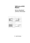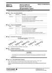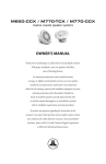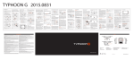
1
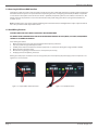
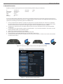
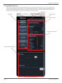
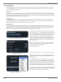
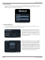
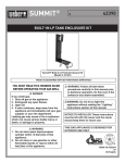
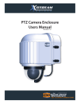
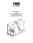
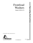
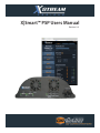
X|Smart™ PSP Users Manual
Revision 1.0
X|Smart™ Users Manual
Table of Contents
Copyright Information........................................................................................................................................................................................................3
Limited Warranty...................................................................................................................................................................................................................4
Installation Guidelines........................................................................................................................................................................................................5
Security Notes........................................................................................................................................................................................................................5
Final Installation Notes.......................................................................................................................................................................................................5
Section 1: Introduction.......................................................................................................................................................................................................6
1.1 X|Smart_PSP Features................................................................................................................................................................................7
1.2 Applications...................................................................................................................................................................................................8
1.3 Accessory Power Connections & Indicators.......................................................................................................................................8
1.4 Accessing the X|Smart Web Interface...................................................................................................................................................9
1.5 Good Wiring Practices................................................................................................................................................................................9
Section 2: Network Connection......................................................................................................................................................................................10
Control Window 3: Overview...........................................................................................................................................................................................11
3.1 Control Window...........................................................................................................................................................................................12
System Setup Windows.....................................................................................................................................................................................................14
4.1 Control Interface Tab..................................................................................................................................................................................14
4.2 System Settings Tab....................................................................................................................................................................................14
Optional Accessories...........................................................................................................................................................................................................17 Page 2
X Stream Designs, Inc.
X|Smart™ Users Manual
Copyright Information
This document is Copyright ©2014 by X Stream Designs, Inc. All rights reserved.
All trademarks are the property of their respective owners.
All parts of this product and design including but not limited to firmware, hardware design, schematics, PCB layout, concept, graphics, users
manual, etc., are property of X Stream Designs, Inc. ©2014. X|Smart may not be opened, disassembled, copied or reverse-engineered.
No part of this manual may be reproduced or transmitted in any form or by any means, electronic or mechanical, including photocopying or
scanning, for any purpose other than the personal use by the purchaser of this product. X Stream Designs, Inc., assumes no responsibility for any
errors that may appear in this document.
Whereas reasonable effort has been made to make the information in this document as useful and accurate as possible, X Stream Designs, Inc.
assumes no responsibility for the application, usefulness, or completeness of the information contained herein. Under no circumstance will X
Stream Designs, Inc. be responsible or liable for any damages or losses including direct, indirect, special, incidental, or consequential damages
or losses arising from either the use of any information contained within this manual or the use of any products or services referenced in this
manual.
X Stream Designs, Inc. reserves the right to change any product’s features, specifications, documentation, warranties, fee schedules, and conditions at any time and without notice.
Page 3
X Stream Designs, Inc.
X|Smart™ Users Manual
LIMITED WARRANTY
X Stream Designs warrants that, during the Warranty Period, the Product will, with normal use and service, be free from faulty parts, manufacture or workmanship.
X Stream Designs extends the following warranty for all X Stream Designs Products unless otherwise stated, to the original owner/purchaser of the Product for a
period of 12-months, from date of shipment.
This warranty shall be voided if the article in question is improperly installed, applied, operated or maintained; subjected to overload, misuse, negligence or an accident; or repaired or altered outside of the X Stream Designs warehouse or by anyone other than an authorized X Stream Designs service partner under direction
of X Stream Designs. Products manufactured by others, but supplied by X Stream Designs as part of a X Stream Designs Product, are not warranted by X Stream
Designs, and Customer’s sole recourse if any such product should fail shall be under the warranty, if any, of such other manufacturer.
Customer’s sole and exclusive remedy against X Stream Designs and X Stream Designs’ only obligation, for breach of warranty, shall be, at X Stream Designs’ option, the repair or replacement (with either a refurbished or new Product) of any Product that on X Stream Designs’ examination is found to be defective at the
time of delivery due to faulty workmanship and/or defective material, but only if the Customer submits a claim in writing to X Stream Designs within the warranty
period.
When making a warranty claim, the Customer must request an RMA from X Stream Designs. Upon issuance of the RMA, the Customer will forward the Product to
X Stream Designs for evaluation. Freight and insurance will be paid for by the Customer.
The Customer is responsible for repackaging Products returned in suitable
packing material to prevent damage in transit. If X Stream Designs ascertains that the Product is defective due to faulty workmanship and/or defective material,
X Stream Designs shall send the repaired Product or a replacement Product to the Customer. X Stream Designs may choose the method of delivery and will pay
freight and insurance and credit the Customer for freight and insurance costs resulting from return shipment from the Customer to X Stream Designs authorized
by the RMA. Products or product parts which have been replaced shall be the property of and retained by X Stream Designs. If X Stream Designs’ determines that
the Product is not defective due to faulty workmanship and/or defective material or that the warranty has been voided, the Product shall be returned to the Customer, if the Customer requests. In such case, freight and insurance shall be paid by the Customer.
MAKING A WARRANTY CLAIM:
1. Customer must inform X Stream Designs as soon as the warranty claim arises by calling 1-858-768-2992 or sending an email to support@xstreamdesigns.
com.
2. Customer must provide original proof of purchase and a description of the fault and any other relevant material.
3. If the warranty claim is accepted, X Stream Designs will issue a RMA and give Customer authorization to ship faulty parts/and or the entire Product to X
Stream Designs for repair or replacement.
4. X Stream Designs will, at its cost, repair or replace any faulty parts and/or the entire Product and return the Product back to Customer.
If you do not wish to be bound by any of the provisions in this warranty, please return the product(s) immediately to X Stream Designs.
For further Warranty information contact:
X Stream Designs, Inc.
Customer Service Department
2120 Jimmy Durante Blvd., Suite 110
Del Mar CA 92014
U.S.A.
1-858-768-2992
Disclaimer of Warranties
EXCEPT FOR THE WARRANTIES STATED IN SECTION 11, THE PRODUCTS ARE SUPPLIED “AS IS”, “WHERE IS” AND “WITH ALL FAULTS”. X STREAM DESIGNS DISCLAIMS
ALL OTHER WARRANTIES WITH RESPECT TO THE PRODUCTS, EITHER EXPRESS OR IMPLIED, ARISING BY OPERATION OF LAW, COURSE OF DEALING, USAGE OF TRADE
OR OTHERWISE, INCLUDING BUT NOT LIMITED TO THE IMPLIED WARRANTIES OF MERCHANTABILITY AND FITNESS FOR A PARTICULAR PURPOSE.
Indemnification Customer shall indemnify, defend and hold X Stream Designs harmless from all claims, including but not limited to all claims filed by third parties, for injuries,
harms, losses or damages of any kind, (a) caused by or resulting from, (i) the Product after it has been delivered, (ii) the improper use, repair, maintenance or operation of the Product by Customer, (iii) the failure of Customer to adequately train personnel in the operation of the Product, or (iv) the Customer’s failure to comply
with applicable laws or regulations or (b) to products manufactured by the Customer or to products of which the Customer’s products form a part.
The Customer consents to the jurisdiction of any court or arbitral tribunal in which any third party files a claim for injuries, harms, losses or damages allegedly
caused by any Product sold to Customer.
Limitation of Liability
IN NO EVENT SHALL X STREAM DESIGNS BE LIABLE FOR ANY SPECIAL, INDIRECT, CONSEQUENTIAL, PUNITIVE OR EXEMPLARY DAMAGES OR LOSSES ARISING OUT
OF ANY BREACH OF WARRANTY, FAULTY PRODUCT, DELAY IN THE DELIVERY OF THE PRODUCT, PRODUCT LIABILITY, FAILURE TO WARN, RECALL OR OTHERWISE,
IRRESPECTIVE OF THE CAUSE, INCLUDING BUT NOT LIMITED TO, LOSS OF PRODUCTION, LOSS OF PROFIT AND LOSS OF GOODWILL.
Notice of Claims
Claims or complaints as to defects and/or delay in delivery of the Products or other claims shall be submitted in writing by Customer to X Stream Designs without
undue delay.
Page 4
X Stream Designs, Inc.
X|Smart™ Users Manual
Installation Guidelines
- The X Stream Designs enclosure system should be installed by qualified personnel.
- This unit must not be used for medical, life saving purposes, or for any purpose where its failure could cause serious injury
or the loss of life.
- This unit must not be used in any way where its function or failure could cause significant loss or property damage.
Security Notes
The X|Smart™ system employs a Linux operating system and does have the ability to support features such as telnet, FTP and SSH. For this reason, there is a chance that someone can ‘break in’ to the X|Smart™ system and access other devices on your local
network. As with any device installed on a network, appropriate security precautions should be observed.
If the X|Smart™ system is installed on the Internet, it is recommended that the control password be enabled. Passwords should be at least 8
characters in length and use a combination of upper and lower case letters and numbers. For additional security, a firewall may be used to limit
access to selected IP addresses. Another option may be to set up a Virtual Private Network (VPN) between the network where X|Smart™ resides
and the client machine.
Final Installation Notes
The X|Smart™ product and the integrated 5 port switch (4 available ports) supports 10Mbps ,100Mbps and 1000Mbps network connections.
Only one of the ports provides switched 48VDC Power Over Ethernet (POE).
Page 5
X Stream Designs, Inc.
X|Smart™ Users Manual
Section 1: Introduction
X|Smart_PSP (Power Spectrum Platform) is a multi-function web-enabled power supply chassis facilitating control and monitoring of the camera
enclosure system. The X|Smart_PSP power supply chassis consists of two 12VDC, two 24VDC and one 48VDC POE user accessible accessory
power ports. It can be controlled and/or monitored over any IP network including private networks and the Internet. Using a web browser,
users can control the dome wiping and cleaning process, check washing fluid levels, remotely turn on and/or off the accessory power ports,
monitor and control temperature setttings and monitor power and temperature in real time as well as over a period of time via the graphing
functionality.
Figure 1.1 - X|Smart_PSP Power Supply Chassis
Figure 1.2 - X|Smart_PSP PCBA
Figure 1.3 - X|Smart_PSP Web Interface
Page 6
X Stream Designs, Inc.
X|Smart™ Users Manual
1.1 X|Smart_PSP Features
115/230VAC to 24VDC 150 Watt Internal Power Supply
The X|Smart_PSP power supply chassis has an integrated 115/230VAC power supply capable of providing 150 Watts of power at
24VDC to the PCBA and enclosure system.
12VDC Power Ports [2]
Capable of providing up to 53 Watts of power to accessory devices, the two 12VDC ports can be remotely controlled (on/off ) via
the web interface.
24VDC Power Ports [2]
Capable of providing up to 70 Watts of power to accessory devices, the two 24VDC ports can be remotely controlled (on/off ) via
the web interface.
48VDC Power Over Ethernet Port (POE) [1]
Capable of providing up to 38 Watts of power to POE devices, the non IEEE-802.3 compliant POE port can be remotely controlled
(on/off ) via the web interface.
Internal & External Digital Temperature Sensors
Embedded on the X|Smart PCBA, the internal digital temperature sensor allows you to monitor the internal temperature of the
enclosure in real-time. It is also integrated into the climate control system triggering heat on/off when the system is set to AUTO.
The External Temperature Sensor is an optional accessory from X Stream Designs allowing you to monitor the outside temperature
in real-time.
Integrated 5 Port 10/100Mbps Network Switch
The X|Smart_PSP system employs a 5 Port 10/100Mbps network switch giving the user 3 available ports after populating the uplink port with your network connection. The 5th port connects to the integrated Linux embedded controller.
Power Supply Fans [2]
Integrated into the power supply chassis are two 2 power supply fans. The fans can be remotely controlled (on/off ) via the web
interface.
Input Voltage Monitoring
Monitor the PCBA input voltage in real-time via the web interface and detect potential power issues before it becomes a
problem.
Input Current Monitoring
Monitor the PCBA input current in real-time via the web interface and detect potential power issues before it becomes a
problem.
Load Monitoring (Watts)
The watt is a derived unit of power which can be used to express the rate of energy or transfer of energy with respect to time.
Ohm’s Law (W = Voltage x Current) allows us to derive the enclosure power load and monitor it in realtime. A great feature for offgrid and remote applications or the energy concious user.
Climate Control System
Control the interior enlosure temperature setting via the web interface by choosing heat AUTO and setting the temperature or
Heat OFF. Integrated on the PCBA is a thermostatic snap switch used to control the air conditioning system in X|Cold model enclosure systems.
Real Time Clock
Manually set the time & date or synchronize via an NTP server.
Fluid Level Meter
Monitor the washing fluid level in real-time via the web interface. Level values are FULL, 2/3, 1/3 and RESERVE.
Event Scheduler
Schedule the X|Rain & X|Clear enclosure systems to Clean and/or Wipe at pre-difined intervals via the web interface.
Graphing
Monitor Power Usage & Temperature over a period of time in graph format.
Page 7
X Stream Designs, Inc.
X|Smart™ Users Manual
1.2 Applications
The X|Smart_PSP power supply system and web based user interface was designed to meet numerous industry applications. It
gives the user much more functionality than just an interface to trigger wiping and cleaning of the enclosure dome. With the
integrated relays and power sensors, users can remotely control multiple accesory power ports and monitor power usage in realtime. A great tool for remote camera systems and especially off-grid powered systems.
The X|Smart_PSP system is integrated into our X|Clear and X|Rain enlosure systems and is also available as an option in our X|Mod,
X|Cold and X|Heat enclosure systems. The next generation X|Smart_PSP will include an integrated UPS with battery backup power
and integrated solar charge controller systems.
Example Applications Include Coastal Monitoring Cameras, Rainy Environments, Off-Grid Powered Camera Locations, Remote
Camera Applications and any installation that requires housing additional camera accesorry components.
1.3 Accessory Power Connections & Indicators
System LED
[2] 12VDC Ports
[2] 24VDC Ports
[1] 48VDC POE Port
115/230VAC Input
[3] 10/100Mbps
RJ45
24VAC Input
Figure 1.4 - X|Smart_PSP Connections & Indicators
[2] 12VDC Accessory Power Ports
The X|Smart system has two 12VDC accessory power ports. Each port is individually controlled (on/off ) via the X|Smart web interface. Next to each accessory port is a green indicator LED which illuminates when power is available on the port.
[2] 24VDC Accessory Power Ports
The X|Smart system has two 24VDC accessory power ports. Each port is individually controlled (on/off ) via the X|Smart web interface. Next to each accesory port is a green indicator LED which illuminates when power is available on the port.
[1] 48VDC Accessory Power Over Ethernet Network Port
The X|Smart system has one 48VDC accessory POE network port which is controlled (on/off ) via the X|Smart web interface. Next
to the POE port is a green indicator LED which illuminates when 48VDC power is available on the port.
[3] 10/100Mbps RJ45 Network Switch Ports
The X|Smart system has 3 non POE powered 10/100Mbps Network switch ports. Two are accesible on the face of the X|Smart
chassis while the third is underneath as indicated in Figure 1.4 above.
115/230VAC & 24VAC Power Inputs
The X|Smart power supply chassis takes either 115/230VAC or 24VAC input power. The 115/230VAC power input is located on the
face of the X|Smart power supply chassis as shown in Figure 1.4 above. The 24VAC power input is located underneath the power
supply chassis.
System LED
The System LED is a blue LED light which blinks every 5 seconds indicating the system is live and operating normally. Allow approximately 10-15 seconds at power up for the System LED to start blinking.
Page 8
X Stream Designs, Inc.
X|Smart™ Users Manual
1.4 Accessing the X|Smart Web Interface
The X|Smart system has a built-in web server that provides the user with a simple web interface for controlling and monitoring the
PTZ camera enclosure system. No special software is required to get started. Configuring the network parameters is explained
in more detail in subsequent sections of this user manual. By default, the X|Smart system has an IP address of 192.168.1.25. The
default username and password to access the control interface and system settings tabs after accessing the web interface are
u: admin / p: xsd
Note: Depending on the setup of your network, configuring your network router and / or managed switches may be required in order to
access the system from outside of your local network.
1.5 Good Wiring Practices
CAUTION: MAKE SURE THAT POWER IS COMPLETELY OFF BEFORE WIRING.
MIS-WIRING OR MIS-CONFIGURATION COULD CAUSE PERMANENT DAMAGE TO THE X|SMART_PSP PCBA, THE EQUIPMENT
TO WHICH IT IS CONNECTED OR BOTH.
Correct Wiring Procedures:
1. Make sure that power is disconnected completely from the X|Smart_PSP Chassis.
2. Strip each power wire approximately 4 to 5 mm.
3. Carefully insert the bare end of the wire into the appropriate (-/+) power port minding the voltage (12VDC or 24VDC).
4. Make sure that no bare wire shows.
5. Give the wire a slight tug to make sure that it is in the power port securely.
6. Re-Apply power to the X|Smart_PSP chassis.
Making clean and proper connections to the accessory power ports on the X|Smart_PSP power supply chassis is important. See
Figures 1.6.1 and 1.6.2 below.
Figure 1.6.1 - Exposed Wire & Poor Connection
Page 9
Figure 1.6.2 - Good Connections
X Stream Designs, Inc.
X|Smart™ Users Manual
2. Network Connection
By default, your X|Smart_PSP system will arrive with the following network settings and credentials:
IP: Subnet Mask: Gateway IP:
DNS1:
DNS2: HTTP Port:
192.168.1.25
255.255.255.0
192.168.1.1
8.8.8.8
192.168.1.1
80
Username: Password: admin
xsd
To access the web interface of the X|Smart_PSP system and configure the settings for your network, power up the enclosure system and step through the following instructions. It is suggested to do the initial connection and configuration of the X|Smart_PSP
system prior to mounting the enclosure system at the installation site.
1.
2.
3.
4.
5.
6.
7.
Connect an Ethernet Cable between a computer (or laptop) direct to any of the ethernet ports on the face or underneath
the power supply chassis. This can be done direct or through a network switch (Figure 2.1.2). It is suggested that no other
devices are connected to the network if connecting through a switch to avoid potential IP Address conflicts.
Configure your computer to have an IP address within the same 192.168.1.X subnet (EX: 192.168.1.20) and Subnet Mask:
255.255.255.0
It is not necessary to input a Gateway IP address or DNS information. If you enter this information, use 192.168.1.1 for the
Gateway IP Address, DNS1: 8.8.8.8 and DNS2: 8.8.4.4
Apply and/or save those settings on your computer.
Open up your favorite web browser. Firefox and Chrome work well.
Enter the following into the URL Window; http://192.168.1.25:80 then hit enter.
The XSmart web interface will load in the web browser and look similar to Figure 2.1.1 below. You are now connected with
the X|Smart web interface.
Figure 2.1.2 - X|Smart Connection - Computer Direct & Through a Networks Switch
Figure 2.1.1 - X|Smart Initial Web Interface Window
Page 10
X Stream Designs, Inc.
X|Smart™ Users Manual
3. Control Window Overview
When first connecting to the web interface of the X|Smart system, the control window will appear. You can also navigate to the
control window by clicking on the control tab. It is within the control window that you monitor power and temperatures, control
the CID washing and wiping functions and power on and off accessory power ports. The system by default does not require a
username or password when first accessing the web interface of the X|Smart system.
CONTROL Tab
Navigation Tabs
Status Pane
CID Control Pane
Component Control Pane
Power & Temperature Graphs
Figure 3 - X|Smart Control Window
Page 11
X Stream Designs, Inc.
X|Smart™ Users Manual
3.1 Control Window
The Control Window is comprised of the Status Pane, Navigation Tabs, CID Control Pane, Component Control Pane and the Temperature & Power Graphs. Each section of the control window and what is displayed can be customized as desired by the user
within the CONTROL INTERFACE tab.
Status Pane
This section of the control window displays the System Name, Time/Date, Enclosure Model, Exterior Temperature (If exterior temperature probe is installed), Interior Temperature, Input Voltage, Input Current and Load. By default, the system displays temperature in both Fahrenheit and Celius. This can be changed to ºF, ºC or both as well as what is displayed in the status pane within the
CONTROL INTERFACE and SYSTEM SETTINGS navigation tabs.
Navigation Tabs
The navigation tabs allow the user to navigate from the Control Window to system setup menus. When first navigating to either
the CONTROL INTERFACE tab or the SYSTEM SETTINGS tab, the system will ask for a username and password. The default username is admin and the default password xsd (password is case sensitive).
CID Control Pane
It is within this section of the Control Window that the user controls the dome washing function and the dome wiping function.
In the X|Clear model enclosure, the CID Control Pane will display the Fluid Bottle Level meter, Wash and Wipe functions. In the
X|Rain model enclosure, the CID Control Pane will only display the Wipe function. If the X|Smart_PSP system is installed in the
X|Heat, X|Cold or X|Mod enclosures as an option, the CID Control Pane will not be displayed.
Figure 3.1 - Fluid Bottle Level Meter
The Fluid Bottle Level meter displays the level of the washing fluid
at four levels - FULL, 2/3, 1/3 and RESERVE. When the fluid bottle is
filled completely, FULL will be displayed for approximately 15 wash
cycles. 2/3 will then be displayed until approxmiately 30 wash
cycles are completed. 1/3 will then be displayed until approximately 50 wash cycles are completed. When no bar is displayed
in the meter, the fluid bottle has reached the RESERVE level. This
happens at approximately 70 was cycles with approximately 20
was cycles remaing.
Note: There is no indicator as to when the fluid bottle is completely
empty. Damage to the system components can occur if the system
runs out of fluid and continued attempts
are made to clean the dome.
Figure 3.2 - CID Control
The wash and wipe functions can be activated in one of two ways.
1.) One Time Wash or Wipe - When desired, simply depress the
WASH or WIPE button to the right of WASH ONE TIME or WIPE ONE
TIME (Figure 3.2).
2.) Scheduled Intervals - User selectable intervals are enabled by
a mouse click to the boxes left of WASH EVERY and WIPE EVERY
(Figure 3.2 and 3.3). A check mark will appear in the box indicating
that the interval wash or wipe function is enabled. Once enabled,
the interval for each function is selected via a drop down menu
found just to the right of WASH EVERY and WIPE EVERY (Figure 3.3).
Note: A check mark in the box left of WASH EVERY or WIPE EVERY indicating that the interval wash or wipe is enabled MUST appear BEFORE
you can select an inverval with the drop down menu.
Figure 3.3 - Interval Selection
Page 12
X Stream Designs, Inc.
X|Smart™ Users Manual
Component Control Pane
This section of the Control Window allows the user to monitor and control the accessory power ports, the heating system and the
internal circulation fans. By default, the system displays the 12VDC and 24VDC accessory ports as 12VDC_1, 12VDC_2, 24VDC_1
and 24VDC_2 where “_1” is the port on the left and “_2” is the port on the right for both the 12VDC and the 24VDC ports. The
Power Over Ethernet port is displayed as POE by default. The naming of these accessory power ports can be changed as desired
within the CONTROL INTERFACE tab.
Examples: 12VDC_1 to NVR or POE to Sony PTZ Camera (Figure 3.4).
Enabling and disabling power to the accessory power ports is
achieved by clicking the mouse in the appropriate control box
to the right. The indicator is either green when enabled or red
when disabled. There is also an orange status indicator which
appears when the port of system is enabled. The default state
for each component on powering up the system can be setup
within the CONTROL INTERFACE tab.
Figure 3.4 - Component Control
The enclosure heating system is set to AUTO and 10ºC/50ºF
by default. The options are OFF or AUTO. If OFF, the Internal
Heater Lower Limit value is not selectable. If Internal Heater is
set to AUTO, the user is able to select the Internal Heater Lower
Limit value via a drop down menu (Figure 3.5). No matter what
temperature is selected, the internal heating system turns off
at 21ºC / 70ºF. The heat will again turn on automatically if the
internal temperature drops to the Internal Heater Lower Limit.
Figure 3.4 - Internal Heat Selection DRop Down Menu
Temperature & Power Graphs
(Figure 3.6) The X|Smart web interface displays the power
usage, the internal tempeture of the enclosure and the
exterior temperature if the optional external termperature
probe is installed over a period of 24 hours. The Power
Usage graph displays the current wattage each hour. The
Temperature Graph displays the temperature in Fahrenheit
each hour. Within the CONTROL INTERFACE tab, the user is
able to enable or disable displaying the power and temperature graphs in the Control Window.
Figure 3.6 - Power & Temperature Graphs
Page 13
X Stream Designs, Inc.
X|Smart™ Users Manual
System Setup Windows
Accessing the system setup windows is achieved by clicking on the CONTROL INTERFACE and SYSTEM SETTINGS tabs. When clicking on either of these tabs for the first time, you will be asked for a username and password (Figure 4.1). The username is always
admin and the default password is xsd . Both are case sensitive.
Figure 4.1 - Login Window
4.1 CONTROL INTERFACE Tab
Under the CONTROL INTERFACE tab, you will find the Main Header Text, Display Item and Display Status configuration options.
Each section and the configuration options are explained below in detail.
The Main Header Text allows you to enter text or a name which
will appear above the time and date in the Status Pane. Simply
enter text into the text input box and click on the update button.
This section also allows you to select Auto Refresh - you or no and
the Refresh Rate. It is suggest to set Auto Refresh to yes with a
refresh rate of 10 seconds or less. The refresh rate determines how
often the X|Smart user interface polls the S|Smart_PSP system for
updated status information.
Figure 4.2 - Main Header Text
The Display Item configuration section allows you to customize the
name of each accessory power port and select whether it should
be displayed in the Component Control section of the CONTROL
window. It also allows the user to enable or disable the power
port on system startup. To display a power accesorty port in the
Component Control section of the CONTROL window, mouse click
in the box to the right of the Custom Name text input box (A check
mark will appear), Customize the name of the port (Ex: Sony PTZ
Cam), then mouse click on the update button. In order to enable
a power port on startup, mouse click in the box under On Startup.
The red ball will move to the right and turn green indicating that
the power port will be “ON” when the system starts up.
Figure 4.3 - Display Item
Page 14
X Stream Designs, Inc.
X|Smart™ Users Manual
The Display Status configuration section allows the user to enable
or disable Status Pane status readings as well as enable or disable
displaying the Power Usage and Temperature Graphs.
To disable displaying a status parameter, simply mouse click on the
check mark under Display. To Enable displaying a status parameter, simply mouse click in the empty box. A check mark will appear.
After enabling or disabling a status display parameter, mouse click
on the update button.
Figure 4.4 - Display Status
4.2 SYSTEM SETTINGS Tab
Under the SYSTEM SETTINGS tab, you will find the Network Settings, System Settings, User Password, Authentication, Time/Date
Settings and Enclosure Reporting configuration options. Each section and the configuration options are explained below in detail.
The Network Settings section of the SYSTEM SETTINGS tab allows
the user to change the network settings of the X|Smart_PSP system. It is suggested to contact the administrator of your network
for these settings prior to changing these settings and connecting
to your network. Selecting DHCP yes will configure the system to
get its network settigns automatically via the DHCP server on your
network. Selecting DHCP “No” allows the user to assign static IP
Address network settings into the X|Smart system. Enter the IP
Address, Subnet Mask, Gateway (Router), DNS1/DNS2 information
and mouse click on the update button. When doing so, you will
temporarily lose connectivity to the X|Smart system. If the new IP
Address information entered is part of a different network subnet
(Example: 10.0.0.25), you will have to change the network settings
on your computer to allow access to that subnet in order to access
the system again.
Figure 4.5 - Network Settings
Page 15
The HTTP port by default is port 80. This can be changed as
desired. If the HTTP port is changed to 8000 for example, the new
URL to access the X|Smart system will be http://<IP_Address>:8000
When changing the HTTP port, mouse click on the update button.
You will then have to use the new URL format above in order to
access the X|Smart system.
X Stream Designs, Inc.
X|Smart™ Users Manual
The System Settings section of the SYSTEM SETTINGS tab is mostly
reserved for future software releases and X Stream Designs XSD
Central portal system for accessing and controlling multiple enclosure systems from a single web interface.
The Temperature Display unit settings - Fahrenheit and Celcius
can be changed here. Choose to display temperature in ºC , ºF or
Both by selecting the appropriate field and mouse clicking on the
update button.
Figure 4.6 System Settings
The User Password section of the SYSTEM SETTINGS tab allows the
user to change the default admin password xsd . Enter the new
password into both the New Password and Re-Enter New Password
text fields and mouse click on the update button. The system will
immediately require the user to enter the new login in credentials.
Enter admin and your new password, then click Login.
Figure 4.7 - User Password
The Authentication section of the SYSTEM SETTINGS tab allows the
user to require or not require a password in order to control any of
the funtions found within the CONTROL tab. To require or not require a password for CONTROL tab functions, click in the appropriate field then mouse click the update button.
Figure 4.8 - Authentication
Page 16
Note: Login credentials are always required to change any of the
settings parameters found in the CONTROL INTERFACE and SYSTEM
SETTINGS tabs.
X Stream Designs, Inc.
X|Smart™ Users Manual
The Time/Date Settings section of the SYSTEM SETTINGS tab allows
the user to set the time and date of the X|Smart system either
manually or via an NTP server (Figures 4.9 & 4.10).
To set the Time and Date manually, via the drop down menu select
MANUAL, adjust the date and Time, then mouse click on the update button. Note: The time is in 24 Hour Format only.
To set the Time and Date via an NTP (Network Time Protocol) server,
via the drop down menu select SYNC W/ NTP, enter the NTP server
into the text field, select SYNC ON POWER UP yes or no, enter the
UTC Offset (Example: PST = -8:00), choose the SYNC INTERVAL, then
mouse click on the update button.
Figure 4.9 - Manual Setting
Figure 4.10 - Sync. w/ NTP Server
The Enclosure Reporting section of the SYSTEM SETTINGS tab
is reserved for future software releases and X Stream Designs
XSD Central portal system for accessing and controlling multiple
enclosure systems from a single web interface. At this time, setting
Disable Reporting & Alerts to either Yes or No does nothing.
Figure 4.11 - Enclosure Reporting
Optional Accessories
The following optional accessories are available for purchase from X Stream Designs. Please contact an X Stream Designs representative via phone, our website at http://xstreamdesigns.com or email [email protected].
Accessory
Description
Part Number
External Temperature Sensor
1 Wire Stainless Steel External Temperature
Senor Probe
XSD-EXTTEMP-P
Accesory Shelf - Short
Black Powder Coated Perforated Aluminum
Accessory Shelf Mount
XSD-SHELF-S
Accessory Shelf - Full
Black Powder Coated Perforated Aluminum
Accessory Shelf Mount
XSD-SHELF-F
Replacement Rotating Dome Lens
Replacement Rotating Dome Lens
XSD-RDL
Replacement Fixed Dome Lens
Replacement Fixed Dome Lens
XSD-FDL
XSD Camera Mounting Plate
XSD Camera Mounting Plate
XSD-CMP
XSD _L - Extended Camera Mounting Tray
Convert your X|Model short enclosure system
to a long version with the XSD Extended
Camera Mounting Tray
XSD-ECMT
XSD _S - Short Camera Mounting Tray
Convert your X|Model long enclosure system
to a short version with the XSD Short Camera
Mounting Tray
XSD-SCMT
Page 17
X Stream Designs, Inc.