1
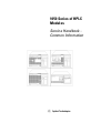
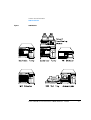
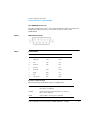
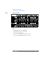
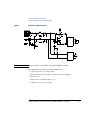
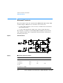
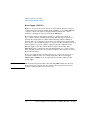
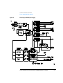
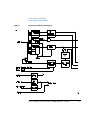
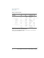
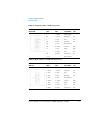
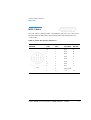
1050 Series of HPLC Modules Service Handbook Common Information Copyright Agilent Technologies 2001 All rights reserved. Reproduction, adaption, or translation without prior written permission is prohibited, except as allowed under the copyright laws. Part No. NONE 11/2001 Printed in Germany Warranty IMPORTANT NOTE The information contained in this document is subject to change without notice. This version of the 1050 service manual includes all sections from the 01050-90102 edition 4 (1995) and G1306-90102 edition 2 (May 1994). It merges both sections, the MWD and the DAD. Agilent Technologies makes no warranty of any kind with regard to this material, including, but not limited to, the implied warranties or merchantability and fitness for a particular purpose. Agilent Technologies shall not be liable for errors contained herein or for incidental or consequential damages in connection with the furnishing, performance, or use of this material. Agilent Technologies Hewlett-Packard-Strasse 8 76337 Waldbronn Germany The series I opticals information (79854A MWD) information has been removed (product went out of support during 2000). Part numbers have been updated as of 11/2001. Contact your local Agilent support office in case of part number issues or upgrades. The latest version of this manual is available as Adobe Acrobat Reader (PDF) version only and can be downloaded from the Agilent Technolgies web page www.agilent.com. Contents 1 Common: General Information This chapter provides general information about the 1050 Series of HPLC Modules 5 Safety Information 6 General 6 Operation 6 Safety Symbols 8 Radio Interference 9 Manufacturer’s Declaration Sound Emission 9 9 Manufacturer’s Declaration UV-Radiation 10 Solvent Information 9 11 Flow Cell 11 Solvents 11 1050 Introduction 12 The Modules Overview 12 1050 Identification 14 Repair Policy 14 2 Common: Electronic Information This chapter provides common electronic information about the 1050 Series of HPLC Modules 15 Overview 17 Common Main Processor Board (CMP) 18 Common 1050 Functions CMP Details 20 Remote Control 23 18 Service Handbook for 1050 Series of HPLC Modules - 11/2001 3 Contents Firmware Board (FIM) Firmware Description 29 29 Fluorescent Indicator Module (FIP) External Contacts 32 Power Supply (DPS-B / DPS-A) 33 31 General Description 33 Base Supply (DPS-B) 34 Lamp Supply (DPS-A) 36 Communication Interface (CIB / CRB) 40 3 Common: Cable Information This chapter provides information on cables for the 1050 Modules 43 Overview 44 Analog Cables 46 Remote Cables 48 BCD Cables 53 4 Service Handbook for 1050 Series of HPLC Modules - 11/2001 1 1 Common: General Information This chapter provides general information about the 1050 Series of HPLC Modules Common: General Information Safety Information Safety Information The following general safety precautions must be observed during all phases of operation, service, and repair of this instrument. Failure to comply with these precautions or with specific warnings elsewhere in this manual violates safety standards of design, manufacture, and intended use of the instrument. Agilent Technologies assumes no liability for the customer’s failure to comply with these requirements. General This is a Safety Class I instrument (provided with terminal for protective earthing) and has been manufactured and tested according to international safety standards. Operation Before applying power, comply with the installation section. Additionally the following must be observed. Do not remove instrument covers when operating. Before the instrument is switched on, all protective earth terminals, extension cords, auto-transformers, and devices connected to it must be connected to a protective earth via a ground socket. Any interruption of the protective earth grounding will cause a potential shock hazard that could result in serious personal injury. Whenever it is likely that the protection has been impaired, the instrument must be made inoperative and be secured against any intended operation. Make sure that only fuses with the required rated current and of the specified type (normal blow, time delay, and so on.) are used for replacement. The use of repaired fuses and the short-circuiting of fuseholders must be avoided. Some adjustments described in the manual, are made with power supplied to the instrument, and protective covers removed. Energy available at many points may, if contacted, result in personal injury. Any adjustment, maintenance, and repair of the opened instrument under voltage should be avoided as much as possible. When inevitable, this should be carried out by a skilled person who is aware of the hazard involved. Do not attempt internal service or adjustment unless another person, capable of 6 Service Handbook for 1050 Series of HPLC Modules - 11/2001 Common: General Information Safety Information rendering first aid and resuscitation, is present. Do not replace components with power cable connected. Do not operate the instrument in the presence of flammable gases or fumes. Operation of any electrical instrument in such an environment constitutes a definite safety hazard. Do not install substitute parts or make any unauthorized modification to the instrument. Capacitors inside the instrument may still be charged, even though the instrument has been disconnected from its source of supply. Dangerous voltages, capable of causing serious personal injury, are present in this instrument. Use extreme caution when handling, testing and adjusting. When working with solvents please observe appropriate safety procedures (for example, goggles, safety gloves and protective clothing) as described in the material handling and safety data sheet by the solvent vendor, especially when toxic or hazardous solvents are used. Service Handbook for 1050 Series of HPLC Modules - 11/2001 7 Common: General Information Safety Information Safety Symbols Table 1 shows safety symbols that are used on the instrument and in the manuals. Table 1 Safety Symbols Symbol Description The apparatus is marked with this symbol when the user should refer to the instruction manual in order to prevent risk of harm to the operator and protect the apparatus against damage. Indicates dangerous voltages. Indicates a protected ground terminal. Eye damage may result from directly viewing the light produced by the deuterium lamp used in this product. Always turn off the deuterium lamp before opening the metal lamp door on the side of the instrument. WA R N I N G A warning alerts you to situations that could cause physical injury or damage to the equipment. Do not proceed beyond a warning until you have fully understood and met the indicated conditions. C A UT I O N A caution alerts you to situations that could cause a possible loss of data. Do not proceed beyond a caution until you have fully understood and met the indicated conditions. 8 Service Handbook for 1050 Series of HPLC Modules - 11/2001 Common: General Information Radio Interference Radio Interference Manufacturer’s Declaration This is to certify that this equipment is in accordance with the Radio Interference Requirements of Directive FTZ 1046/1984. The German Bundespost was notified that this equipment was put into circulation, the right to check the series for compliance with the requirements was granted. Test and Measurement If test and measurement equipment is operated with equipment unscreened cables and/or used for measurements on open set-ups, the user has to assure that under operating conditions the radio interference limits are still met within the premises. Sound Emission Manufacturer’s Declaration This statement is provided to comply with the requirements of the German Sound Emission Directive of 18 January 1991. This product has a sound pressure emission (at the operator position) < 70 dB. • Sound Pressure Lp < 70 dB (A) • At Operator Position • Normal Operation • According to ISO 7779:1988/EN 27779/1991 (Type Test) Service Handbook for 1050 Series of HPLC Modules - 11/2001 9 Common: General Information UV-Radiation UV-Radiation Emissions of ultraviolet radiation (200-315 nm) from this product is limited such that radiant exposure incident upon the unprotected skin or eye of operator or service personnel is limited to the following TLVs (Threshold Limit Values) according to the American Conference of Governmental Industrial Hygienists: Table 2 UV-Radiation Limits Exposure/day Effective Irradiance 8 hours 0.1 µW/cm2 10 minutes 5.0 µW/cm2 Typically the radiation values are much smaller than these limits: Table 3 UV-Radiation Typical Values Position Effective Irradiance Lamp installed, 50-cm distance average 0.016 µW/cm2 Lamp installed, 50-cm distance maximum 0.14 µW/cm2 10 Service Handbook for 1050 Series of HPLC Modules - 11/2001 Common: General Information Solvent Information Solvent Information Observe the following recommendations on the use of solvents. Flow Cell Long term operation at pH > 11 should be avoided. Never leave strongly alkaline solutions in the flow cell without flow. Solvents Always filter solvents through 0.4 µm filters, small particles can permanently block the capillaries. Avoid the use of the following steel-corrosive solvents: • Solutions of alkali halides and their respective acids (for example, lithium iodide, potassium chloride, and so on). • High concentrations of inorganic acids like sulfuric acid, especially at higher temperatures (replace, if your chromatography method allows, by phosphoric acid or phosphate buffer which are less corrosive against stainless steel). • Halogenated solvents or mixtures which form radicals and/or acids, for example: 2CHCl3 + O2 → 2COCl2 + 2HCl This reaction, in which stainless steel probably acts as a catalyst, occurs quickly with dried chloroform if the drying process removes the stabilizing alcohol. • Chromatographic grade ethers, which can contain peroxides (for example, THF, dioxane, di-isopropylether) such ethers should be filtered through dry aluminium oxide which adsorbs the peroxides. • Solutions of organic acids (acetic acid, formic acid, and so on) in organic solvents. For example, a 1-% solution of acetic acid in methanol may attack steel. • Mixtures of carbon tetrachloride with 2-propanol or THF dissolve stainless steel. Service Handbook for 1050 Series of HPLC Modules - 11/2001 11 Common: General Information 1050 Introduction 1050 Introduction The Modules Overview 1050 is a series of HPLC products based on a modular concept. The necessary functions are broken down into independent stand-alone modules with standardized external design hydraulic- and external interfaces. Following modules will be available at introduction: Table 4 1050 Modules Module Product Number 1050 Isocratic Pump 79851A 1050 Quaternary Pump 79852A 1050 Quaternary Pump (bio compatible) 79852B 1050 Variable Wavelength Detector 79853C 1050 Multiple Wavelength Detector 79854A 1050 Diode Array Detector G1306A 1050 Autosampler 79855A 1050 Autosampler (bio compatible) 79855B 12 Service Handbook for 1050 Series of HPLC Modules - 11/2001 Common: General Information 1050 Introduction Figure 1 1050 Modules Service Handbook for 1050 Series of HPLC Modules - 11/2001 13 Common: General Information 1050 Introduction 1050 Identification Each module is identified by a 5 digit product number and a 10 unit serial number on a label attached to the wall inside the module. The first four digits of the serial number are the serial prefix. The letter identifies the country of origin. The last five digits are an identification number unique to each module. Any changes to the modules will be covered initially by Service Notes. They will be sent out to all Service personnel prior to implementation of the change to the instrument. With every reprint these changes will be incorporated into the documentation. Repair Policy Major mechanical and electrical assemblies inside the 1050 modules will be repaired on an assembly-exchange level. All other items have to be repaired on board/component level. Repair procedures are given in the respective sections of this manual (refer to Table of Contents). Assemblies can be set up to the Blue Stripe Exchange system or can be removed. If in doubt contact Waldbronn Product Support (Europe/ICON) or Little Falls Product Support (USA/Canada). 14 Service Handbook for 1050 Series of HPLC Modules - 11/2001 1 1 Common: Electronic Information This chapter provides common electronic information about the 1050 Series of HPLC Modules Common: Electronic Information This chapter gives information about the common electronics used in more than one of the 1050 Series of modules: • Overview • Common Main Processor (CMP) • Remote Control • Firmware Boards (FIM, SFW) • Fluorescent Indicator Module (FIP) • External Contacts • Poweer Supplies (DPS-B, DPS-A) • Communication Interfaces (CIB, CRB) 16 Service Handbook for 1050 Series of HPLC Modules - 11/2001 Common: Electronic Information Overview Overview Some of the electronic boards are used in more than one 1050 module. The following table shows common electronic assemblies: Table 1 Common Electronic Boards Description Modules Part Number Exchange Power Supply (DPS-B) pump, sampler 5061-3374 01050-69374 Power Supply (DPS-A) MWD, DAD, VWD 5061-3375 01050-69375 Common Main Processor (CMP) pump, sampler, MWD, DAD 5061-3380 01050-69580 Display Interface Board (FIP) pump, sampler, MWD, DAD 5061-3376 no Communication Interface (CIB) pump, sampler 5061-3382 no Communication Interface (CRB) MWD, DAD 5062-2482 no Service Handbook for 1050 Series of HPLC Modules - 11/2001 17 Common: Electronic Information Common Main Processor Board (CMP) Common Main Processor Board (CMP) Repair Level: Board Table 2 Part Numbers for CMP Board Item Part Number CMP Board (Exchange) 01050-69580 CMP Board (NEW) 5061-3380 Common 1050 Functions • display handling • keyboard polling • remote control input and output • leak sensing • option interfacing • time programming • method storage • module configuration • memory switching • 32 kbyte RAM with battery back-up for parameter storage. 18 Service Handbook for 1050 Series of HPLC Modules - 11/2001 Common: Electronic Information Common Main Processor Board (CMP) Figure 1 Blockdiagram CMP Service Handbook for 1050 Series of HPLC Modules - 11/2001 19 Common: Electronic Information Common Main Processor Board (CMP) According to the above functions the main processor board contains some basic hardware which is common to all 1050 modules: • 68008 main processor running at 8 MHz; • 64 kByte RAM (32 kbyte RAM with battery back-up for parameter storage. The data will be lost when CMP is removed from the slot); • interrupt logic for system communication; • 3 channel software controlled timer; • interface to keyboard/display module; • remote I/O hardware; • leak sensor electronics; • interface to backplane bus; • watchdog hardware. Firmware is not part of this board, because parts of the main processor’s software are module specific. The main processor firmware will be located on the ’personality module’ (AQB-, RAD, VMD-Board) or on an optional board. CMP Details Interrupt system There are one non-maskable interrupt six high priority hardware interrupt lines and seven low priority mail interrupt lines. The non-maskable interrupt is connected to the powerfail line of the power supplies (DPS-A/B). The high priority interrupt lines are: One from timer 6840 for hardware synchronization and five from remaining slots (these lines are disabled by SOK- = HIGH (system not ok). The low priority interrupt lines are: Five lines from all slots except power supply used for communication with local processors via dual port RAMs and two lines for CMP controlled software interrupts. Watchdog timer (Test for CPU hang-up) This circuitry is software retriggerable and is disabled during CPU initialization. In case of CPU hang-up SOK line is set the CPU is halted and the remote line ’shutdown’ is set. 20 Service Handbook for 1050 Series of HPLC Modules - 11/2001 Common: Electronic Information Common Main Processor Board (CMP) LED on board There is a RED LED on the board which is the output of the watchdog circuit. It is ON during initialization and when the processor has a hang-up (LD 101). Programmable timer It includes 3 independent timers: • Timer 1 is connected to the backplane bus it’s free for module special use. • Timer 2 is used as software timer for the CMP. • Timer 3 is used to generate the BUS ERROR signal. Reset system A harware reset is performed • at power • manually by on-board switch Hardware reset will reset all devices connected to the bus but main processor can reset these devices by software too. Reset for display unit The latch for the status LEDs and the brigthness control will not be reseted by power on or by software reset. The alphanumeric display is reseted at power on. I/O Two remote connectors are at the rear panel. They provide start, stop, not ready, shutdown, prepare-run and power on signals. The remote lines are input and output and are decoupled for EMC. The shutdown line is set by hardware in the case of leak or CPU hang-up. System control The POK (peripheral OK) is driven from all devices. The SOK- (system OK) • is outputted from main processor to all devices; • is hardware and software controlled • disables/enables all devices by main software; • disables all devices if main processor watchdog becomes active (main processor hang-up); Service Handbook for 1050 Series of HPLC Modules - 11/2001 21 Common: Electronic Information Common Main Processor Board (CMP) All devices are enabled after initialization. Bus control After bus request the main processor will pass bus control to the requesting external controller. The local main processor areas including I/O are accessible too. This may be a feature for diagnostics or if data rate is increasing to much with later options. For this second case an external fast transfer hardware (for example DMA device) could do the transfers after set-up by the main processor. Leak sensing The leak detection circuit is located on the CMP board and checks continuously for presence and leak conditions. If the sensor is missing (defect) or in leak condition the PTC is cooled down the error message appears. When the module is turned on the leak message is disabled for some time to allow the sensor to reach its working range. Working condition of the PTC Normal: about 75°C 400...500 Ohm Error: below 55°C about 150 Ohm Actions: ❏ Check for leak. ❏ Check connector of the sensor. ❏ Check resistance of leak sensor. ❏ Change leak sensor. ❏ Change CMP board. ❏ Change FIM board. 22 Service Handbook for 1050 Series of HPLC Modules - 11/2001 Common: Electronic Information Common Main Processor Board (CMP) Remote Control The CMP board provides two remote connectors. Remote control allows easy connection between single instruments or systems to ensure coordinated analysis with simple coupling requirements. When 1050 System is started from the autosampler the following signals can be measured at the remote lines. The START REQUEST signal is only available when the autosampler was started from any other module (remote configuration set to HPSystem). Figure 2 Remote Control Analysis Service Handbook for 1050 Series of HPLC Modules - 11/2001 23 Common: Electronic Information Common Main Processor Board (CMP) For the 1050 Series of HPLC Modules the subminiatur D connector is used. Each module provides two remote connectors which are both parallel and inputs/outputs (wired-or technique). To provide maximum safety within a distributed analysis system one line is dedicated to SHUT DOWN the system’s critical parts in case any module detects a serious problem. To detect whether all participating modules are switched on or properly powered one line is defined to summarize the POWER ON state of all connected modules. Control of analysis is maintained by signal readiness READY for next analysis followed by START of run and optional STOP of run triggered on the respective lines. In addition PREPARE and START REQUEST may be issued. Signal description SHUT DOWN (L) System has serious problem (e.g. leak: stops pump). Receiver is any module capable to reduce safety risk. POWER ON (H) All modules connected tosystem are switched on. Receiver is any module relying on operation of others. READY (H) System is ready for next analysis. Receiver is any sequence controller. PREPARE (L) Request to prepare for analysis (e.g. calibration detector lamp on). Receiver is any module performing preanalysis activities. START REQUEST (L) Request to start injection cycle (e.g. by start key on any module). Receiver is the autosampler. START (L) Request to start run / timetable. Receiver is any module performing runtime controlled activities. STOP (L) Request to reach system ready state as soon as possible (e.g. stop run abort or finish and stop injection). Receiver is any module performing runtime controlled activities. The signal level are defined as standard TTL levels (0 V is logic true, + 5 V is logic false). The remote lines can be input or output (wired or technique). • Fan-out is 10 • Input Load 2 kOhm against + 5 V • Outputs are open collector type 24 Service Handbook for 1050 Series of HPLC Modules - 11/2001 Common: Electronic Information Common Main Processor Board (CMP) The REMOTE Connector To help you make the correct connections the signals carried on each pin are listed in the table below (the colors refer to wires of remote cable 01046-60201). Figure 3 APG Remote Connector Table 3 Remote Signals Pin Signal Active Color 1 Digital ground 2 Prepare run LOW brown 3 Start LOW gray 4 Shut down LOW blue 5 Reserved 6 Power ON HIGH yellow 7 Ready HIGH red 8 Stop LOW green 9 Start request LOW black white pink Remote Configuration The 1050 Series provides three remote configurations: HPsystem Start of automatic operation from any modules’ start key. Start request is outputted. GLOBAL Synchronized start of several modules for a single run. Start / Stop is outputted. LOCAL Single modules’ start. No pulses outputted. Service Handbook for 1050 Series of HPLC Modules - 11/2001 25 Common: Electronic Information Common Main Processor Board (CMP) Figure 4 Table of line definition Notes • Y1 is done by balance key of MWD only. • Y2 BALANCE on detectors is performed. • Y3 is not used in the module. • The remote line SHUT DOWN will always be active. • The remote line POWER ON will not be processed. 26 Service Handbook for 1050 Series of HPLC Modules - 11/2001 Common: Electronic Information Common Main Processor Board (CMP) Figure 5 Schematic of Remote Control N OT E Above schematic is for Pump, Autosampler, MWD and DAD. The signal level are defined as standard TTL levels • (0 V is logic true, +5 V is logic false). • The remote lines can be input or output (wired or technique). • Fan-out is 10 • Input Load >=2.2 kOhm against + 5 V • Outputs are open collector type Service Handbook for 1050 Series of HPLC Modules - 11/2001 27 Common: Electronic Information Common Main Processor Board (CMP) Figure 6 Board Layout CMP 28 Service Handbook for 1050 Series of HPLC Modules - 11/2001 Common: Electronic Information Firmware Board (FIM) Firmware Board (FIM) Repair Level: Exchange Board Table 4 Part Numbers for Firmware Boards Item Part Number Exchange for Pumps (79851/2A/B) on RAD Board 01018-66518 no for Autosamplers (79855A/B) on VMD Board 01078-66504 no for Multiple Wavelength Detectors (79854A) on AQB Board 01048-66504 no for Diode ArrayDetectors (G1306A) on AQB Board G1306-66524 no Firmware Description Figure 3-7 shows the firmware structure for the 1050 Series of modules (pump, autosampler, multiple wavelength detector and diode array detector). As many as possible tasks use the same core firmware and only special routines for each module are developed seperate (control of the hardware sensors motors and so on). This common structure gives maximum flexibility for later development of similar products. It is obvious that also in the common firmware different commands display contents method parameters and so on. appear (Dialog, Method Handler, Parameter Handler). But nevertheless the structure is the same. In each part of the firmware there exist tables which hold the module specific commands parameters and so on, which are all handled under the same conditions. The firmware works with a foreground background mode. All time critical tasks (timetable execution, sensor and motor information) are working in the foreground mode and have highest priority. All other tasks share the remaining time in the background. If there are no tasks running the processor goes into the idle state. The firmware per module has approxmiately 300 kByte, where 170 kByte is Common and 130 kByte module specific). Service Handbook for 1050 Series of HPLC Modules - 11/2001 29 Common: Electronic Information Firmware Board (FIM) The firmware is located on the module specific firmware board which is piggy back on the personality board of each module (AQB-, RAD- or VMD-board) and can be exchanged easily. Figure 7 Firmware Structure 30 Service Handbook for 1050 Series of HPLC Modules - 11/2001 Common: Electronic Information Fluorescent Indicator Module (FIP) Fluorescent Indicator Module (FIP) Repair Level: Board or Fuse ICP1 Table 5 Part Numbers for FIP Board Item Part Number used for FIP Board 5061-3376 pumps, autosampler, MWD amd DAD Fuse 1 A 2110-0099 The FIP module is located behind the keyboard module of pump, autosampler and multiple wavelength detector. The function of the FIP module is to provide an interface between a host system and the user. Messages can be displayed with up to 32 characters (2 lines x 16 characters/line). A matrix keyboard is scanned for numeric or special function input and status information is displayed through 4 LEDs. The characters are displayed in a 5 x 7 dot matrix. In case of a dark display, check the on board fuse ICP1 (1 A) which is soldered in close to the connector P1/P2. Figure 8 Board Layout FIP Service Handbook for 1050 Series of HPLC Modules - 11/2001 31 Common: Electronic Information External Contacts External Contacts The personality boards of the 1050 modules (MWD/DAD: AQB, Pumps: RAD and Autosampler: VMD) have two external conacts at the rear. • 1 contact without supply (contact closure) <newline>max. 30 V/250 mA (fused with 250 mA) • 1 contact with internal 24 V supply (max. 250 mA output with fuse) The schematic for all three boards (AQB, NMD and RAD) is in general the same. Only the values of the components vary from board to board due to internal specifications. Figure 9 External Contacts Table 6 Components of External Contacts Components AQB RAD VMD L1, L2, L3, L4 4.7 µH 10 µH 1 µH C1, C2, C6, C7 100 nF 1 nF C3, C4, C8, C9 10 nF 10 nF C5, C10 1 nF 10 nF Fuse F250 mA (2110-0004) 32 Service Handbook for 1050 Series of HPLC Modules - 11/2001 Common: Electronic Information Power Supply (DPS-B / DPS-A) Power Supply (DPS-B / DPS-A) Repair Level: Fuses and DPS-B / DPS-A Table 7 Part Numbers for LUC/LPC Board Item Part Number used for DPS-B (Exchange) 01050-69374 Pumps and Autosamplers DPS-B (New) 5061-3374 Pumps and Autosamplers DPS-A (Exchange) 01050-69375 MWD, DAD, VWD DPS-A (New) 5061-3375 MWD, DAD, VWD Fuse for 110 V operation 3 A 2110-0003 Fuse for 220 V operation 2 A 2110-0002 General Description The power supply is a primary switching regulated type. It consists of two parts. the Base Supply and the Lamp Supply. The Base Supply provides outputs of +5 V, ±19 V, +24 V and +36 V. In addition the Lamp Supply provides all circuits necessary for the operation of a deuterium lamp. Service Handbook for 1050 Series of HPLC Modules - 11/2001 33 Common: Electronic Information Power Supply (DPS-B / DPS-A) Base Supply (DPS-B) Figure 11 on page 59 shows the base part of the DPS-A. The line voltage is rectified filtered and switched with about 50 kHz by a power MOS-FET. The complete control of frequency and pulsewidth is made by the control board #1 containing the logic needed and the FET driver. The isolation between the primary and the secondary part is made by opto-couplers and the switching transformer. The DC-output voltages are generated by single-phase rectifiers and LC-filtering with the additional features: The +36 V output has an separate over-voltage protection to limit the voltage to +45 V maximum. The +5 V output contains an additional analog series regulator to provide a stable output for all load conditions under different applications. The synchronization input is used in the 1050 MWD/DAD only to synchronize the switching frequency to a value of three times (54 kHz) of the diode array readout frequency. This output is not used in the other modules. The power supply status is monitored by the processor system to detect a powerfail condition and to save all important data. The Power Supply STATUS LED (GREEN) at the rear panel shows the OK condition of the power supply. N OT E OK means that the pulsewidth of the switching FET is inside the allowed limits. OK does not means that all voltages at the output are present (for example a broken inductor is not detected). 34 Service Handbook for 1050 Series of HPLC Modules - 11/2001 Common: Electronic Information Power Supply (DPS-B / DPS-A) Figure 10 Block Diagram DPS-B (Base Supply) Service Handbook for 1050 Series of HPLC Modules - 11/2001 35 Common: Electronic Information Power Supply (DPS-B / DPS-A) Lamp Supply (DPS-A) Figure 12 on page 61 and Figure 13 on page 62 show the additional circuits necessary for the deuterium lamp: • a DC output of 5.5 V for the regulated heater output (located on the primary board); • a regulated constant current source with selectable current of 320 mA, 360 mA or 400 mA; • a 600 V lamp ignition circuit; • a 12 V regulated output for future use. WA R N I N G Hazardous voltage present at the output connector with instrument power cord connected to AC line. The main feature of this power supply is a low noise current source for the deuterium lamp. For realization a pulse-width modulated DC-DC converter (36 V input, 170 V no load output) is built-up with a switching FET and high voltage transformer. The pulse-width is regulated so that the DC-output is about 12V above the actual anode voltage of the deuterium lamp. This design allows minimum power loss if the anode voltage varies from lamp to lamp and by aging between 65 V and 100 V. The final regulation to the selected current is made by an analog power regulator. Again the switching frequency is synchronized to 54 kHz in the 1050 MWD/DAD. 36 Service Handbook for 1050 Series of HPLC Modules - 11/2001 Common: Electronic Information Power Supply (DPS-B / DPS-A) Figure 11 Block Diagram DPS-A (Lamp Supply I) Service Handbook for 1050 Series of HPLC Modules - 11/2001 37 Common: Electronic Information Power Supply (DPS-B / DPS-A) Figure 12 Block Diagram DPS-A (Lamp Supply II) 38 Service Handbook for 1050 Series of HPLC Modules - 11/2001 Common: Electronic Information Power Supply (DPS-B / DPS-A) Lamp Ignition To ignite the deuterium lamp a 0.5 µF capacitor loaded with 600 V is discharged via a 10 kOhm resistor to the anode. These 600 V are generated by a separate winding. The lamp status output signal shows "OK" if the lamp current has the selected value. Otherwise an error message is generated. The heater output made by a series regulator is in the pre-heating status 2.5 V always. After ignition a different output voltage is selected depending on the lamp type used: In the 79853C VWD, 79854A MWD and the G1306A DAD, the heater is switched off after ignition. The 12 V low noise output is made by a series regulator connected to the +19 V output. Service Handbook for 1050 Series of HPLC Modules - 11/2001 39 Common: Electronic Information Communication Interface (CIB / CRB) Communication Interface (CIB / CRB) Repair Level: Exchange Board Table 8 N OT E Part Numbers for CRB Board Item Part Number used for CIB Board (NEW) 5061-3382 Pumps and Autosampler CRB Board (NEW) 5062-2482 79854A MWD / G1306A DAD This section describes the communication interface for the 1050 Pumps (79851/2A/B), Autosamplers (79855A/B), Multiple Wavelength Detectors (79854A) and Diode Array Detector (G1306A) only. The communication interface for the 1050 Variable Wavelength Detector (79853C) is described in the chapter of the 1050 VW Detector. The communication interface board is necessary for the control by a Personal Computer and to connect printer or plotter devices. The communication interface board provides one GPIB and one RS-232 interface. The CRB for the 1050 MWD/DAD has a 96 kbyte runbuffer for the data/spectrum operation with the Multiple Wavelength Detector. The interface is located in Slot #2 of the module. 40 Service Handbook for 1050 Series of HPLC Modules - 11/2001 Common: Electronic Information Communication Interface (CIB / CRB) Compatibilities Table 9 CIB/CRB Compatibility Instrument CIB CRB Firmware 1050 Pump R P REV 3.1 1050 Sampler R P REV 3.1 1050 MWD C R REV 3.1 1050 DAD C R REV 1.0 R recommended configuration P possible but not neccessary C only for instrument control Firmware To use the communication interface board it is mendatory to have the 1050 Modules equipped with the latest firmware revisions (see Table 13). Baud rate The board contains a baudrate generator. The baudrate is setable up to 19200 baud from the keyboard. The transmitter and receiver baudrate are independent adjustable. RS-232 Interface The implemented serial interface is a subset of the RS-232 standard only. It contains at PIN 2 RxD receive data (data input) PIN 3 TxD transmit data (data output) PIN 4 GND (Ground) The 1050 modules are designed as DCE (data communication equipment) without hardware handshake. Service Handbook for 1050 Series of HPLC Modules - 11/2001 41 Common: Electronic Information Communication Interface (CIB / CRB) 42 Service Handbook for 1050 Series of HPLC Modules - 11/2001 1 1 Common: Cable Information This chapter provides information on cables for the 1050 Modules Common: Cable Information Overview The 1050 Modules provide • Analog Signal Output (Pumps, Detectors) • Remote Control Connector (all) • BCD Connector (Autosampler) WA R N I N G Never use cables other than the ones supplied by Agilent Technologies to ensure proper functionality and compliance with safety or EMC regulations. 44 Service Handbook for 1050 Series of HPLC Modules - 11/2001 Common: Cable Information Overview Table 1 Cables Overview Type Description Part Number Analog cables 3390/2/3 integrators 01040-60101 3394/6 integrators, 35900A A/D converter 35900-60750 General purpose (spade lugs) 01046-60105 3390 integrator 01046-60203 3392/3 integrators 01046-60206 3394 integrator 01046-60210 3396A (Series I) integrator 03394-60600 Remote cables 3396 Series II / 3395A integrator, see page 74 BCD cables GP-IB cable 3396 Series III / 3395B/96C/97A integrator 03396-61010 1100 / 1050 modules / 1046A FLD / 35900A A/D converter 5061-3378 1040 DAD / 1090 liquid chromatographs / SDM 01046-60202 3392/3 integrators obsolete 3396 integrator 03396-60560 General purpose (spade lugs) 18594-60520 1100 module to ChemStation, 1 m 10833A 1100 module to ChemStation, 2 m 10833B 1100 module to ChemStation, 5 m 10833D Service Handbook for 1050 Series of HPLC Modules - 11/2001 45 Common: Cable Information Analog Cables Analog Cables One end of these cables provides a BNC connector to be connected to 1050 Series modules. The other end depends on the instrument to which connection is being made. 1050 to 3390/2/3 Integrators Connector 01040-60101 Pin 3390/2/3 Pin 1050 Signal Name 1 Shield Ground 2 3 Not connected Center 4 5 Signal + Connected to pin 6 Shield Analog - 6 Connected to pin 4 7 Key 8 Not connected 1050 to 3394/6 Integrators Connector 35900-60750 Pin 3394/6 Pin 1050 1 46 Signal Name Not connected 2 Shield Analog - 3 Center Analog + Service Handbook for 1050 Series of HPLC Modules - 11/2001 Common: Cable Information Analog Cables 1050 to BNC Connector Connector 8120-1840 Pin BNC Pin 1050 Signal Name Shield Shield Analog - Center Center Analog + Pin 1050 Signal Name 1050 to General Purpose Connector 01046-60105 Pin 3394/6 1 Not connected 2 Black Analog - 3 Red Analog + Service Handbook for 1050 Series of HPLC Modules - 11/2001 47 Common: Cable Information Remote Cables Remote Cables One end of these cables provides a Agilent Technologies APG (Analytical Products Group) remote connector to be connected to 1050 Series modules. The other end depends on the instrument to be connected to. 1050 to 3390 Integrators Connector 01046-60203 48 Pin 3390 Pin 1050 Signal Name Active (TTL) 2 1 - White Digital ground NC 2 - Brown Prepare run Low 7 3 - Gray Start Low NC 4 - Blue Shut down Low NC 5 - Pink Not connected NC 6 - Yellow Power on High NC 7 - Red Ready High NC 8 - Green Stop Low NC 9 - Black Start request Low Service Handbook for 1050 Series of HPLC Modules - 11/2001 Common: Cable Information Remote Cables 1050 to 3392/3 Integrators Connector 01046-60206 4 - Key Pin 3392/3 Pin 1050 Signal Name Active (TTL) 3 1 - White Digital ground NC 2 - Brown Prepare run Low 11 3 - Gray Start Low NC 4 - Blue Shut down Low NC 5 - Pink Not connected NC 6 - Yellow Power on High 9 7 - Red Ready High 1 8 - Green Stop Low NC 9 - Black Start request Low Pin 3394 Pin 1050 Signal Name Active (TTL) 9 1 - White Digital ground NC 2 - Brown Prepare run Low 3 3 - Gray Start Low NC 4 - Blue Shut down Low NC 5 - Pink Not connected NC 6 - Yellow Power on High 5,14 7 - Red Ready High 6 8 - Green Stop Low 1 9 - Black Start request Low 1050 to 3394 Integrators Connector 01046-60210 13, 15 N OT E Not connected START and STOP are connected via diodes to pin 3 of the the 3394 connector. Service Handbook for 1050 Series of HPLC Modules - 11/2001 49 Common: Cable Information Remote Cables 1050 to 3396A Integrators Connector 03394-60600 Pin 3394 Pin 1050 Signal Name 9 1 - White Digital ground NC 2 - Brown Prepare run Low 3 3 - Gray Start Low NC 4 - Blue Shut down Low NC 5 - Pink Not connected NC 6 - Yellow Power on High 5,14 7 - Red Ready High 1 8 - Green Stop Low NC 9 - Black Start request Low 13, 15 Active (TTL) Not connected 1050 to 3396 Series II / 3395A Integrators Use the cable 03394-60600 and cut pin #5 on the integrator side. Otherwise the integrator prints START; not ready. 50 Service Handbook for 1050 Series of HPLC Modules - 11/2001 Common: Cable Information Remote Cables 1050 to 3396 Series III / 3395B Integrators Connector 03396-61010 Pin 33XX Pin 1050 Signal Name 9 1 - White Digital ground NC 2 - Brown Prepare run Low 3 3 - Gray Start Low NC 4 - Blue Shut down Low NC 5 - Pink Not connected NC 6 - Yellow Power on High 14 7 - Red Ready High 4 8 - Green Stop Low NC 9 - Black Start request Low 13, 15 Active (TTL) Not connected 1050 to 1050, 1046A or 35900 A/D Converters Connector 5061-3378 Pin 1050 / … Pin 1050 Signal Name 1 - White 1 - White Digital ground 2 - Brown 2 - Brown Prepare run Low 3 - Gray 3 - Gray Start Low 4 - Blue 4 - Blue Shut down Low 5 - Pink 5 - Pink Not connected 6 - Yellow 6 - Yellow Power on High 7 - Red 7 - Red Ready High 8 - Green 8 - Green Stop Low 9 - Black 9 - Black Start request Low Service Handbook for 1050 Series of HPLC Modules - 11/2001 Active (TTL) 51 Common: Cable Information Remote Cables 1050 to 1090 LC, 1040 DAD or Signal Distribution Module Connector 01046-60202 5 - Key Pin 1090 Pin 1050 Active Signal Name (TTL) 1 1 - White Digital ground NC 2 - Brown Prepare run Low 4 3 - Gray Start Low 7 4 - Blue Shut down Low 8 5 - Pink Not connected NC 6 - Yellow Power on High 3 7 - Red Ready High 6 8 - Green Stop Low NC 9 - Black Start request Low Pin 1050 Signal Name Active (TTL) 1 - White Digital ground 2 - Brown Prepare run Low 3 - Gray Start Low 4 - Blue Shut down Low 5 - Pink Not connected 6 - Yellow Power on High 7 - Red Ready High 8 - Green Stop Low 9 - Black Start request Low 1050 to General Purpose Connector 01046-60201 52 Pin Universal Service Handbook for 1050 Series of HPLC Modules - 11/2001 Common: Cable Information BCD Cables BCD Cables One end of these cables provides a 15-pin BCD connector to be connected to the 1050 Series modules. The other end depends on the instrument to be connected to. 1050 to 3392/3 Integrators (Obsolete) Connector 18584-60510 6 - Key Pin 3392/3 Pin 1050 Signal Name BCD Digit 10 1 BCD 5 20 11 2 BCD 7 80 3 3 BCD 6 40 9 4 BCD 4 10 7 5 BCD 0 1 5 6 BCD 3 8 12 7 BCD 2 4 4 8 BCD 1 2 1 9 Digital ground 2 15 +5V Service Handbook for 1050 Series of HPLC Modules - 11/2001 Low 53 Common: Cable Information BCD Cables 1050 to 3396 Integrators Connector 03396-60560 Pin 3392/3 Pin 1050 Signal Name BCD Digit 1 1 BCD 5 20 2 2 BCD 7 80 3 3 BCD 6 40 4 4 BCD 4 10 5 5 BCD 0 1 6 6 BCD 3 8 7 7 BCD 2 4 8 8 BCD 1 2 9 9 Digital ground NC 15 +5V Low Wire Color Pin 1050 Signal Name BCD Digit Green 1 BCD 5 20 Violet 2 BCD 7 80 Blue 3 BCD 6 40 Yellow 4 BCD 4 10 Black 5 BCD 0 1 Orange 6 BCD 3 8 Red 7 BCD 2 4 Brown 8 BCD 1 2 Gray 9 Digital ground White 15 +5 Vt 1050 to General Purpose Connector 18594-60520 54 Low Service Handbook for 1050 Series of HPLC Modules - 11/2001 In This Book This manual contains technical information about the Agilent 1050 liquid chromatographs. This manual is available as electronic version (Adobe Acrobat Reader file) only.


![Tuning Box V2.0 [MISCE0020000000] – User Manual](http://vs1.manualzilla.com/store/data/006916997_1-f633cd68a1955a465787e5d9b5627253-150x150.png)