1
OWNER
MANUAL
FORWARD
in this manualwill helpyou get
The operatinginstructionsand maintenancerecommendations
acquaintedwith, and get the mostsatisfactoryperformancefromyournew HardinMarineEngine.
How well your enginewill delivertheperformanceit has built into it dependsin the care it receives.
This manual containsa listing of maintenanceproceduresthat should be performedat recommendedintervals.The operatororservicepersonnelresponsibleforthe careof this engineshould
be thoroughly familiarwith these procedures.
This manualcoversthe full line of Hardin GasolineEngines.Theseengineshavemany differences,howeverthe operationand serviceis the same on all theseengines.In this manualwe will
cover the basic operation and serviceas well as some of the differencesbetweenengine models.
Hardin Marinetakes pride in producingenginesof qualityfor a wide varietyof marineapplications. Enginesthat havebeencreatedthrough a greatdeal of researchusing high qualitypartsto
achievethe upmost in performanceand durability.
Should a need for replacementpartsor servicedevelop,contact Hardin Marineor the Hardin
Marine AuthorizedDealernear vou.
TABLEOF CONTENTS"'
IMPO RT A NT
O W NE RR E G IS T R A T IO
......
N
INFORMATION
War r antF
y or m. .
War r antCar
y d ..
En gineS er ialNum b e r. .. ...
PAGE
....,...2
.........2
,, ,... ..,2
. ... ..2
PR EDE LI V E RY
I NS PE C T ION
.....
.......,..3
o w NE RSRE S P O NS | B | L | T |.ES
1 0H ourI ns pec t ion s
.............4
.,.,..4
EN GI NE
S P E CI F I CA T IO ,.
NS
.....5.9
OPERA T I NG
I NS T RU C T ION....
S
Sta r t ingE ngine.
Op e r at ingT heHe a d e r(G a te V a l v e )
Op e r at ing
Hint s. .
1 0 HourB r eak - in
P e ri o d.
l n s t r um ent s
L U BR T CA T I O
. .N
...
En gineO il. . , .
En gineO il Dr aining
P ro d e d u re
Un i v er s al
Dr iv eLine s
Th rot t leCable.
Crankcase
Breather
Filter. .
PC VV alv e
Ma int enanc eS er v i c e Oh a rt..
.... ... .
..... 10-14
........10
.....11
...... 12
..... .. 13
..,.14
... 15-17
...... 15-16
.......... 17
.. .. .. ... . . 17
......... 17
..... . 17
..... 17
.... 18
.
COOLINGSYSTEMS
Description
S al tW aterOperati on
Fl ushi ng
P rocedure
PAGE
. 19-20
. . . . . . . . . . . 20
. . . . . 21
E LE C TR IC ASLY S TE MS
A l ternator
B attery.
SparkPlugs
, . . . . . , 22- 23
. . . . . . 22
. . . . . . . . 22
. 22-23
FU E LS Y S TE M
FuelP umo
Fi l ter..
TypeFuel
C arburetor
, . . . . . . . 23. 24
. . . . . 23
. . . . . . . . . 23
. . . . . . 23
, . , . . 24
TR OU B LE
S H OOTIN G
, . , . . . . , 25- 27
WINTERSTORAGE
,, 28-29
P R E P A R A TION
OF E N GIN EFORS E R V IC E
. . . . . . . 30
W IR IN GD IA GR A M
. . . , 31- 33
W A R R A N TY
S E R V IC E
W A R R A N TY
S TA TE ME N T
. . . . . I nsideBackCover
. . . . . . . . Back Cover
IMPORTANTINFORMATION
IS
POINTEDOUT BY BOLDREDTYPE.
IMPORTANT
OWNER
'FEGTSTRATTON
TNFORMATTON
WARRANTY
FORM
E NG I NES E RI A LNUMB E R
Included with this manual is a warranty form which must be f illed oul and
mailed to Hardin Marine to iniliate the warranty on your new Hardin engine
and/or drive.
This form is pre-addressed
to Hardin Marineand should be filledout by
you and your dealerat the time of purchase.Pleasefill out the card completely,includingthe enginemodel and serialnumberand mail it within 10
days of purchasedate.
The serial number should be recordedon the warrantyform supplied
with this manualand shouldbe relerredto in any correspondence
concerning your engine. This n.umberwrll be rmprintedon your warranty card
which must be used whenever any warranty repairs are made on this
engine.
NOTE:
The FederalBoat Safety Act of 1971 requiresthat registration
listsof marineproductssold in the United Statesbe maintained
by the manufacturersand dealersof theseproducts.Therefore,it
is extremely important that we receiveyour registrationform
both for warranty purposesand to comply with federal regulations.This productowner informationwill alsoenableus to contact you should it become necessaryto change or improvethe
productto protectthe well beingof you, the owner andoperator.
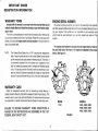
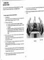
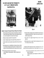
The engine serial number is stamped onto the engine block or head on
the port (left) side of the lronl ol the engine as indicated by the arrows
below. (See figure 1).
WARRANTYCARD
When the completed warranty form is receivedby Hardin Marine, a
plasticOwner'sWarrantyCard will be madeand sentdirectlyto you. This
warrantycard is your only valid identificationfor warrantywork and must
be presentedto a Hardin AuthorizedServiceDealerfor warrantv work.
A
FAILURETO RETURNWARRANTYFORM CONSTITUTES
AS DESCRIBED
IN THE 1971
WAIVEROF ANY NOTIFICATION
FEDERALBOATSAFETYACT.
MODELS
H20s, H225,H260
H280,H333,H400
H405.H425.H430
MODEL
H320
F I G U R E1
PRE-DELIVERY
INSPECTION
The selling dealer should assistyou in being properly equipped according to Coast Guard requirementsand local regulations.He should also
assistyou in watertesting the boat to permityou to familiarizeyourselfwith
the handlingand operationof the boat.
The dealer should conduct a pre-deliveryinspiectionof your boat priorto
deliveryto you. The following items are to be checked:
1. Engine Oil Level
2. Tightnessof fuel and oil lines
3. Battery charge
4. All water hosestight
5. Tightnessof all exhaustmanifold nuts
6. Control adjustments
7. All drain petcocksclosed
8. Alternatorbelt tension
9. Exhausthose and clamps
10. Alternatorfor charge
11. En gin e idle spe ed
12. Bilge area for water leaks
OWNERSRESPONSIBILITIES
A. With the ownershipof a new boatyou receivecertainresponsibilities.
By law you are now responsiblefor alloccupantsof your boat.lt is reguired
that you meet U.S.Coast Guard PersonalFlotationDevice(PFD)requirements.Instructat leastone other personaboardin the basichandlingskills
of your boat to enable that person to operate the boat in case of an emergency.
You shouldobservethe rulesand regulationsof the areain which you are
going to operate your boat in order to protect your passengersas well as
yourself. For additional information contact the local U.S. Power
Squadron,AmericanRed Cross or the State BoatingAuthorities.
B. As a boat owner,you are responsiblefor the normalmaintenanceand
replacementof service items.These are not considereddefects in material
and workmanshipwithin the terms ol the warranty.
i
O WNER 'S
R ESPO N SIBILITIE S
1 OHO U R IN SPECTION
To insurethat you receivethe maximumservicefrom your Hardinequipment yo u sh ou ld a sk your Har din Dealerabout a 10 hour s e r v i c ea n d i n spectio nafte rth e f irst 1 0 hour s of oper at ion.ALTHO UG HT H E 1 0 H O U R
S E R VICElS NOT COV EREDUNDERTHE W ARRANTYP O L I C Y 't h e c o s t
to you will b e minima la nd s houlda m alf unc t ionbe f ound a n d c o r r e c t e da t
this t ime. the inspe ctio nwill pay f or it s elfm any t im es ove r .
The {ollowing is a list ol items to check or service:
1.
2.
3.
4.
5.
6.
7.
B.
9.
10.
Che ck fo r oil, fuel or wat er leak s .
Dra in oil an d re plac ef ilt er . ( s eeoil c hange) .pg. 15 - 1 7
Che ck an d re{ight en engine m ount bolt s .
Check fuel line f ittingsfor tightness.
Check hose clamPsand hoses.
Check the alternatorbelt for correct tension'
Check throttle linkage.
Check the flame arrestor'
Check the fuel filter.
Check all electricalconnectionsfor tightness.
11.
12.
13.
14.
15.
16.
17.
C h e c k e x h a u s tm a n i f o l db o l t s f o r t i g h tn e ss
Check the bilge pump and blower for operation'
Check all switches,lights,and other equipmentfor operation'
Launch the boat.
S t a r tt h e e n g i n ea n d c h e c kt h e t i m i n ga n d d w e l l o fth e d i str i b u to r
Check the operationof all the instruments.
Check the carburetoradjustments.
18. Check for overheatingat maximum RPM's,and at idle RPM's'
19. Check the operationof the steeringand shifting system'
, a | f u n c t i o n so r S i g n So f a b u see xi st i n th e 1 o - h o u
l f a n y d e l i c i e n c i e sm
inspection,it shou|d be noted,broughtto your attention,and correctedat
thar time.
NOTE:
lf defects are found in the equipment that is not supplied by
Hardin Marine, please contact that manufacturerfor serv'ce
information.
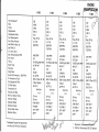
ENGINE
H 205
Net Horsepower.Bore
Stroke
Displacement
CompressionRatio
Fuel Requirements
Fuel Pump Pressure
ldle RPM In Waler Jet
ldle R P M l / O
V or Direct Drive
Max. B e c o m m e n d e dR PM
Point Dwell
T im i n g
S par k P I u g s
P lug c a p
Firing Order
Norm a lO i l P r e s s u r e@ 1 5 0 0Rp M
Oil Viscosityand Type
O il C a p a c i t yw i t h F i t t e r
O il F i l t e rM o d e l
TransmissionOil
Viscosityand Type
Mini m u mB a t t e r yR a t i n g
AlternatorRating
AlternatorN4odel
DistributorModel
Normal Water Temp.
M ax i m u mT e m p .
zvc
4.000
3.480
2 6 2 C.t.
9.3:1
Reg. 87 Oct.
6 - 7 PSI
850 RPM
4600 RPM
390
80 BTDC@600RPM
ACM R4 3 T
.035
165432
35-45 PSt
SAE 30 Class SF, SE
5 Quart Approx.
AC PF 51
See Note
1 o t2
73 Amp
3 5 Am p
I M R 2 0 5 1F
Prestolite
'1200-1800F
2000F
H 225
H 260
225
3.74
3.48
305 C .t.
8.5:1
Reg. 87 Oct.
4-7 P S I
8OOR P M
750 RPM
260
4.00
3.48
350 C.l.
9:1
Reg. 87 Oct.
4-7 P S I
8OORPM
750 R P M
44OORPM
26" Each
8. BTDC@700RPM
MR 43T
.03s
18436572
30-45 P S I
SAE 30 Class SFSE
6 Quart
AC PF 25
See Note
1ot2
73 Amp
35 A mp
I MR 2051 F
YL 67OAV2
1200-1800F
2000F
44OORPM
260 Each
8 BTDC@700RPM
MR 43T
.U JC
18436572
30-45 PSI
SAE 30 Class SF.SE
6 Quart
AC PF 25
See Note
1or2
73 Amp
35 A mp
8 MR 2051 F
YL 67OAV2
1200-180"F
2000F
H 280
280
4.oo
:,T" I
|
Res.87
oct.
4-7Psr
I
I
800RPM
I
800RPM
I
5000RPM
I
260Each
I
8 BrDC@700
RPy
MR43r
I
.o3s
18436572
3o-4sPSt
I
|
I
S A E 30 C l assS F$E
6 Quart
I
A C P F25
|
See Note
I
1or2
|
73 Amp
35 Amp
8MR20s1F
YL 670AV2
12Oo-18OoF
200oF
A
YM*r*'
I
9:1
+r
t' Horsepower
FiguresAre Approximate
And lvlayVary With Each Installation.
I
I
I
I
|
I
I
320
,\
' tty '
+.Jo
V
\
3.850
460 C .l .
8:1
Reg. 87 Oct.
5-7 P S I
9OOR P M
750 R P M
4600 RPM
31.
8 BTDC@550RPT/
A H F 32
.03s
15426378
35-65 P S I
S A E s 0 C l as sS FS E
6 Ouart
ctAz 6731A
S ee N ote
1or2
73 Amp
/
I
I
I
I
3sAmp
8M R20s1F
D3JL12100
120"-180.F
200oF
I
1
//q
I
i
|
I
I
tl
Borswarner;M'#
Twin-DiscTransmissionSAE 30 Deteroenl
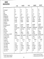
ENG INE
SPECIFICATIONS
H 333
Net Horsepower'.
Bore
Stroke
Displacement
CompressionRatio
Fuel Requirements
Fuel Pump Pressure
ldle RPM In WaterJet
ldle R P M l / O V
Or Direct Drive
I/ax. RecommendedRPM
Point Dwell
T im i n g
Spa r k P l u g s
S pa r k P l u g G a p
F rn n gu r o e r
Nor m a lO i l P r e s s u r e@ 1 5 0 0RPM
O il V i s c o s i t ya n d T Y P e
Oil Capacitywith Filter
O il F i l t e rM o d e l
T ra n s m i s s i oO
ni l
Viscosityand TyPe
Min i m u mB a t t e r yR a t i ng
AlternatorRating
AlternatorModel
Dis t r i b u t oM
r odel
Normal WaterTemP.
Ma x i m u mT e m P .
" Hors e p o w e rF r g u r e sA r e Ap p r o xim a te
A nd M a y V a r yW i t h E a ch ln sta lla tio n .
H 400 0s
H 405
H 42sos
H 4300s
333
4 .2 5
4.0
4 5 4 c.l.
8 :1
Reg. 87 Oct.
4 - 7 PSI
8 5 0 RPM
750 FIPM
400
4.25
4.0
454 C .l .
8.8:'1
Reg. 87 Oct.
4.7 PSI
850 RPM
750 R P M
360
4.25
4.O
454 c.l .
8.8:1
Reg. 87 Oct.
4.7 P S I
850 RPM
750 RPM
425
4.25
4.0
454 C .l .
8.8:1
Reg. 87 Oct.
4.7 PSI
850 RPM
8OORPM
430
4.25
4.O
454 C .l .
8.8:1
Reg. 87 Oct.
4.7 PSI
850 RPM
8OORPM
4600 RPM
260 Each
I BTDC@700RPM
RPM
5OOO
26" Each
I B TD C @700R P M
MR 43 T (AC)
RPM
5OOO
26" Each
RPM
8 BTDC@7OO
MR 43 r (Ac)
52OORPM
26'E ach
I ETDC@700RPM
MH 43 T (AC)
52OORPM
260 Each
RPM
8 BTDC@7OO
MR 43 T (AC)
.035
18436572
30-45 P S I
SAE 30 Class SF.SE
11 Quart
Fram HP '1
See Note
1o(2
73 Amp
35 A mp
8 lvR 2051 F
YL 67OAV2
'1200-'180'F
.035
18436572
30-45 P S I
SAE 30 Class SF.SE
6 Ouart
AC PF 25
See Note
1or2
73 Amp
35 A mp
8 MR 2051 F
YL 67OAV2
120.- 180'F
2000F
.035
18436572
30-45 PSI
SAE 30 Class SFSE
11 Quart
Fram H P 1
See Note
1o(2
73 Amp
35 Amp
8 tvlR2051 F
YL 67OAV2
1200-1800F
2000F
.035
18436572
30-45 P S I
SAE 30 Class SF.SE
'11Quart
M R4 3 T
.035
18436572
30-45 PSI
SAE 30 Class SF.SE
6 Qu a r t
AC PF 25
See Note
1or2
7 3 Am p
3 5 Am p
8 MR 205'1F
YL 67OAV2
1200-1800F
2000F
2000F
Fram HP 1
See Note
1ot2
73 Amp
35 A mp
8 MR 2051 F
YL 67OAV2
1200-1800F
2000F
1. BorgwarnerTiansmissionATF Dextron.
2. Twin-DiscTiansmissionSAE 30 Detergenl
5a
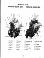
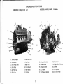
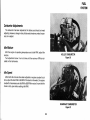
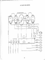
E NG I NES P E CI F I CA T I O NS
MODELS H205,H225, H260, H28OJCt
MODELSH225,H260,H280V-Drive
14
tc
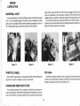
1. FlameArrestor
2. Carburetor
3 . Fu el Pum p Vent
4. Fuel Filter
5 " Oil FillerCap
6 . Fu el Line
7. Fuel Pu m p I n l e t
8. Fuel Pu m p
9. Water lnlet
10. Front Mount
11. Rear M o u n t
' t 2. O il Filt e r
13. ExhaustManifold Drain
14. ExhaustRiser
15. ExhaustOutlet
1 9 . E n g i n eSe r i a lN u m b e r
20. Starter
2 1 . O i l D i p sti ck
16. PCV Valve
17. Oil PressureSender
18. Alternator
22. Trans Oil Dipstick
23. Oil Drain Hose
24. Trans Oil Cooler
I
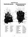
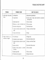
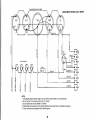
E NG I NE S P E CI F I CA T I O NS
MODELS H333,H405, V'DT|VE
MODELS H333, H4O5 JEt
1. FlameArrestor
2. Carburetor
3. F uelP u mpV e n t
4. F uelFi l te r
5. O il F i l l e rC a p
6. F uelL i n e
7. Fuel Pu m p I n l e t
8. Fuel Pu m p
9. Water Inlet
10. Fr ont M o u n t
11. Rear M o u n t
12. O il Filt e r
13.ExhaustManifold
14.ExhaustRiser
15.ExhaustOutlet
16.PCVValve
S ender
17.Oi l P ressure
18.Alternator
19.E ngi n eSer ialNum be
20.Starter
21.Oi l D ipst ick
22.Oil DrainHose
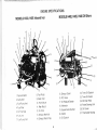
E NG I NES P E CI F I CA T I O NS
MODELSH260,H280TournamentSkier
1. FlameArrestor
2. Carburetor
3. FuelPumpVent
4. FuelFilter
5. Oil FillerCap
6. FuelLine
7. FuelPumpInlet
8. FuelPump
9. Waterlnlet
10.FrontMount
11.RearMount
12.Oil Filter
MODELSH225,H260,H280,H333,H405
InboardFreshWater Gooling
13.ExhaustManifoldDrain
14.ExhaustRiser
15.ExhaustOutlet
16.PCVValve
17.Oil Pressure
Sender
18.Alternator
19.EngineSerialNumber
20.Starter
21.Oil Dipstick
22.TrcnsOil Cooler
23.TransOil Dipstick
24.Oil DrainHose
25. HeatExchanger
26.RadiatorCap
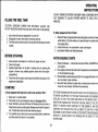
ENG I NE S P E CI F I CA T I O NS
M O D ELS H333,H405 Inboard lro n
MODELS H400, H425,H430 Off Shore
4
8:"
\ ,-.
'w
i%*-15
2 Carb ur et or
ir. Fue l Pum P Vent
4 Fu el Filt er
B Fuel P u m P
9 W at e r l n l e t
10. Fr o n t M o u n t
1 1. Rea r M o u n t
5 OlFi ller CaP
l ne
6 FLreLt
7 Fue l Pum P lnlet
12 O il F i l t e r
13. Ex h a u s tM a n i l o l d
14 Ex h a u s tR i s e r ( P i P e )
1 Fla m eAr r es t or
1 5 . E x h a u s tO u t l e t
1 6 .P C V V a l v e
1 7 . O i l P r e s s u r eS e n d e r
1 8 .A l t e r n a t o r
1 9 . E n g r n eS e r r a lN u m b e r
20.Starter
2 '1. O i l D i P S t i c k
2 2 . Tr a n s Oi l D i PSti ck
Tr a n s Oi l C o o l e r
2 4 . Oi l D r a i n H o se
2 5 Po w e r Ste e r i n gU n i t
2 6 Oi l C o o l e r
2 7 Th e r m o sta tH o u sl n g
OPERATING
INSTRUCTIONS
DO NOT OPERATESTARTERFORMORETHAN 15 SECONDSWITHOUT PAUSINGTO ALLOW STARTERMOTOR TO COOL FOR 2
MINUTES.
FILLINGTHE FUELTANK
CAUTION:GASOLINEVAPORSARE EXPLOSIVE.
ALWAYSUSE
SAFETYMEASURES
WHENFUELING
ANDSTARTING
YOURENGINE.
B. Boatr equlppedwith Foot Throtlle
1. Insurethat all electricalequipmentis turnedoff.
2. Extinguish
all openflameand all smokingmaterial.
3. Thef illerhosenozzleshouldbein contactwiththefill pipeto prevent
sparks.
BEFORESTARTING
'1. Gheckengine,transmission
or outdrivefor properoil level.
2. Checkfuel supply.
3. Operatebilge blowerfor at least4 minutesprior to crankingthe
engineto removeany possiblegasolinefumeslrom the engine
compartment.
4. Checkthat all the engineandexhaustmanifolddrainplugson the
engineare closedtight.
STARTING
A. Boals equlppedwlth slngle leyercontrol such aBMorse"MV-J"
1. Placeleverin neutraldetent.
2. Pull buttonout or pull outwardon leverto disengageshifter.
3. Pumpthrottleby movingshift leverfull foruardand returntwo or
threetimesto primea coldengine.Do notpumpthrottleif engineis
hot. Throttleshouldbe at idlewhen startingengine.
4. Turn ignitionkey to startand as soonas enginestarts,releasekey
and allowswitchto returnto run position.
10
1. Placeshift leverin approximate
neutralandplaceonehandon lever
whilestarting.Thiswill enableyouto keepthe boatin neutralwhen
the enginestarts.
2. Pumpthrottleas in an automobileto startcold engine.
3. Usestarterlimitationas listedpreviously.
AFTERENGINESTARTS
'1. Checkoil pressure
- lt shouldbeat or above10lbs.at idleRPMon a
cold engine.
2. Runengineat closeto idleuntila risein temperature
canbedetected
guage.
on the temperature
3. Placethrottlein neutralandpushbuttonin to engageshiftcable.You
are now readyto get underway.
4. Moveshift leverforwardto placedrivein forwardandas levercontinuesto moveforward,throttlewill be advanced.
JETDRIVEENGINES
MAYBERUNWITHBOATOUTOFWATER
ONLY
IF WATERIS SUPPLIED
TO THE INLETWATERHOSEFORENGINE
COOLING.DO NOT RUN OVER2OOO
RPM OR FOR MORETHAN 1
MINUTEOR DAMAGEMAYOCCURIN THESEALAREAOF THEJET
DRIVE.IF WATERIS NOT SUPPLIED
TO THE ENGINEIT MAY BE
STARTED,
BUT SHOULDONLYBE ALLOWEDTO RUN FORA FEW
SECONDS.
DO NOTSTARTV-DRIVE,
I/O ORDIRECTDRIVEENGINES
WITHOUTA WATERSUPPLYAS DAMAGEMAY BE DONETO THE
WATERPUMP.
OPERATING
INSTRUCTIONS
AWAY
CAUTION: KEEP PASSENGERS
FROM HEADERAT ALL TIMES.
INJURY'
lN SEVERE
ieriune ro Do so couLD RESULT
headersto keep
ln short, allow only enough water to pass through
blueing'
from
the rest of the chrome
headerand engine at al
Keep belongingsanctpassengersaway from
times.
Headers
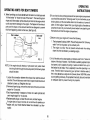
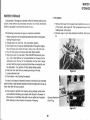
C. Boats equipped with Water lniected
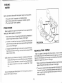
The Gate Valve:
t.
that you can regulatethe
fn" g"t" u"fu" (see fig. 8) is necessaryso
headers'
the
passes
through
amoJnt of water that
Operatingthe Gate Valve:
to headers'
A. Turn valve clockwise to allow more water
the amount of water
restrict
to
clockwise
counter
valve
Turn
B.
to headers.
C.Ge ne ral r ulet olollow: Thef as t er t heboat s p e e d 't h e m o r e
slower the boat
the valve should be turned clockwise' The
counter clockspeed, the more the valve should be turned
wise.
nose of boat is elevated'
3. When running boat on trailer, make sure
this
Procedure:
Always follow
OFF WATER' STOP
START ENGINE,TURN ON WATER.TURN
ENGINEON JE TS O NLY.
equipped with an engine driven
4. For V-Drive engines or engines
water PumPfollow this Procedure:
TURN OFF
TURN ON WATER,START ENGINE.STOP ENGINE,
WATER.
are also hot
Water inlected headersare DRY and HOT at idle They
f ittingand the
the f irst'6 inchesout from the headto the water inlet
chrome will blue to this Point'
could
Failureto do any of above,or if systemis not workingcorrectly
o.
DAMAGE'
ENGINE
result in SEVERE
Figure 8
11
Gate V al v e
OPERATING
INSTRUCTIONS
OPERATING
HINTSFORBOATOWNERS
A. When launching your boat, do not back the trailer in at a fast pace and
"hit the brakes" to "shoot the boat off the trailer". This launching tech_
nique could force water up the exhaustport and into the enginewhich
could cause severedamage to the engine. The flappers in the exhaust
ports and the risers on the exhaust manifold are designed to prevent
this from happeningunder normal use. (Seefigure 9).
B. lf your boat is a low profiletype boatwith an openenginecompartment,
you should be awareof the "followingwake" of your boat when you are
slowing down and the boat setiles back into the water as it comes off
plane. A little nudge of power from your enginejust as the wake ap_
proachesthe stern of your boat will preventwater from splashingover
the transom and into the engine compartment.
C. Beforeturning your engine off, insurethe following:
1. The boatspeedis below2 MpH. Thiswillhelppreventthe,,following
wake" from forcing water up the exhaust ports.
2. The engine is at idle. This will preventexhaustwater from being
drawn into the manifoldsby a coastingengine.
D. At full throttle and top boat speed a jet obtains water from 2" below the
bottom of the boat. However, if full throtfle is suddenly applied at zero
boat speed,a jet is capableof pulling in water and debrisfrom up to 6
feet below the jet intake.This is especiallytrue when operatingin reverse.Thereforewhen maneuveringyour jet boat in shallowwater (6
feet or less) do not use a large burst of power (above 1500RpM) unless
you are gettingunderway.For propellerdriveboats,be sureto maintain
an adequatedepth to preventfouling the propeller.
FIG.9
NOTE: lf the engine should develop a hydro-static lock (water drawn
into the cylinderthroughthe exhaustsystem)the followingsteps
should be taken:
1. Loosenthe connectionbetweenthe exhaustriser and the exhaust
manifold.This will allow any waterthat is trappedinsidethe exhaust
chamberto drain out. Retightenthe riser.
2. Removeall spark plugs,removethe centerwireof the coil,and crank
engine for 15 seconds.
3. Squirt approximately1 teaspoonof motor oil in each cylinderand
crank engine again for 1Sseconds.
4. Replacespark plugs, re-installthe coil wire, and start engine.
lf engine does not sound normal,do not continueto operateyour
"-' engine until your Hardin Marine Dealer has checked it out thoroughly.
1T
OPERATING
INSTRUCTIONS
of the 10 hour break in period'
8. Change oil and filter at the end
9. Change fuel filter'
P E R IOD
ENG I N E1 OH O U RB R E A K -IN
the factoryfor a short ne1i9O.ot
All Hardinenginesnave beentest run at
the systems'This is not to be
all
out
time to make adjustmentsand check
break-inis essentialto
proper
The
engine.
the
of
break-in
considereda
performanceand
engine
maximum
and
assumeminimumoil consumptio-n
servlce.
.10
checkfor oil pressure'leaks'proper
1. First minutes- ldle RPM and
adiustment'
control
proper
cooling, and
RPM '
2. Ne xt 15 minu tes- M inim um planning
no sudden acceleration"
with
RPM
4O0O
to
3. Next 35 minutes- Up
to maximum RPM momentarily'
up
RPM
Varied
minutes
60
Next
4.
with no sudden accelerations'
of your engine'slile vary the
5. For the remainderot the first 10 hours
accelerations
throttle
full
RPM with no
.
in accordancewithnor6. Conduct 10 hour checkand operateengine
l f ( a f t e r i n i t i a | b r e a k - i n p e r i o d ) y o u w i s h t o o p e r a te yo
u r e n g i n e a to r n e a
the craft mav become
Rpru'. in rough watei ionditions wherein
r;-i;;;
thata RPMLimiterbe installedon
temporarilyair-borne,it is recommended
RPM Limiterthat is available
your engineto proteclVoutinu"ltt"nt' The
RPM'This is onlyto preRated
Maximum
at
is
set
i;
;;;t HardinDealer
the enginesuddenly
sho-uld
RPM's
vent the enginefrom go'ng ; e*ti"te
a governorand the same
be
to
designed
not
is
unload under fullthrottle-it
should be observed'
RPM limitationsfor normal operation
BE
T I M E S H OYL D TH E EN GIN E
CAUTION FOR HIGH RPM: AT NO
ENRATING'
MAXIMUM RPM
OPERATEDBEYOND THE SPECITIED
HIGH RPMWILL
OF EXCESSIVELY
NESUiT
IJN
WHICH
FAILURE
GINE
WARRANTY.
THE
UNDER
r.IOiAE REPAIRED
ISAS FOLLOWS:
MAXIMUM RECOMMENDEDRPM
RPM
H405-5000
RPM
H205-4600
RPM
H225-4400
mal Procedures'
H26O-4400RPM
H280-5000 RPM
CAUTION:
UNDERHEAVYLO A D S D U R I N G
D O N OT PUL L SKIERSO RO PERATE
PERI
oD'
inr ro Hou R BREAK - I N
DURING BREAK'IN PERIOD
OBSERVE INSTRUMENTSCAREFULLY
npM
n"iz-o-+'otio
nisi-aooo npN'l
npft'f
Ff+OO-SOOO
RPM
H425-5200
H43O-5200RPM
INSTRUMENTS
your enginegauge::Y:lll":
A good habit to form is that of checking
on the performanceol
information
of
source
minutes.They are the best
your engine.
oF ENGINE'
oPERATIoN
iol.rsune PRoPER
Oil PressureGauqe
7. Also check for:
a. Correct oil level
b. ProPercooling
c. Oil, water or fuel leaks
d. Abnormalvibrationor noise
nuts and clamps
e. Loose mountings,fittings' bolts'
eachtimethe engineis startedandat
snoutooE-cnecked
Oil pressure
3G40
is between
Normaloil pressure
timesdurinj operation'
intermittent
the engineis
when
RPM
900
at
PSI at 1500nprr,t.rvriniirll'oiift"t"u'"
throughlywarmis 10 PSI'
13
EN GIN E
INSTRUMENTS
WaterTemperatureGauge
Tachometer
The water temperature should be observedclosely during the break-in
period. Normal operatingrange is from 120oFto180"F.Maximumoperation temperatureis 195oF. During break-inperiodspecialattentionshould
be given to engine temperature at idle. lf necessary,idle the new engine
higher than normal to provideadequatecooling during break-inperiod.
This indicatesthe RPM at which the engine is running.A decreasein
maximum RPM indicatesa loss of horsepowerf rom the engine and may be
an indicationof needfor a tune.up.An increasefrom the normalmaximum
RPMwould be an indicationthat the jet drive or V-drivemay not be f unctioning properly.
Ammeter
The ammeter indicatesthediflerence betweenalternatoroutput and current "draw". Should the ammeter indicate discharge when the engine is
running above 1000RPM, haveyour dealercheck the circuit as soon as
possible. Normal ammeter reading at averagecurrent draw is 20 amps at
1500RPM. Higher readingswill be seen if the battery has avery low charge.
Voltmeter
The
Yourboatmaybeequippedwith a voltmeterin placeol anammeter.
voltmeterindicatesbatteryand alternatorconditions.Withswitchon,the
of 11to12volts.Duringnormalopvoltmeter
indicates
batteryconditions
erationthe voltmetershouldindicate12.5to 14volts.Duringstarting,9.5
voltsis normal.Shouldvoltagedropto 7 whilecrankingor remainat 12
volts during normaloperationsee your HardinDealerfor an electrical
checkup.
14
1 . Oil Pressure
2. Wator Tempoaature
3. Tachomatel
4. Ammeler or Voltmeter
5. Fuel Guage
-l
EN GIN E
L U B R ICATIO N
E N G INEO IL
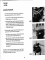
Method A: Remove Oil Through the Oil Pan Drain
Use only SF engineoil (SF oil meetsquality standardGM-6163GMand
FMC-M2C101-C).lt is recommendedthat SAE 30 be usedat all times.The
oil changeintervaland the new enginewarrantyare basedon the useof oil
which meetsthese requirements.Oil conformingto thesestandardscontain detergentanti-wearadditives.
1. With coolantwater flowing through the engineand transmissionor
jet drivein neutral:startengineand allowto reachnormaloperating
temperaturebut do not run longerthan 5 minutes.Shut off engine.
2.Removeoil drain plug locatedin enginecrankcaseoil pan and drain
oil in suitablecontainer.Replacedrain plug.
NOTE: lf you are unableto drain the oil through the oil pan drain plug:
removethe oil dip stick and pump the oil out of the enginevia a
plastictube insertedin the dip stick tube. (See Figure 10)
NON DETERGENTAND LOW QUALITY OILS ARE SPECIFICALLYNOT
R E C OMMENDED.THE USE O F PRO PER ENG I NE O I L A N D O I L
CHANGE INTERVALS IS EVEN MORE IMPORTANT IN A MARINE
ENGINE DUE TO THE HIGHERLOADS AND RPM THAT CAN BE AP_
PLIED TO THE ENGINE FOR EXTENDEDPERIODSOF TIME.
The oil and f ilter that were installedat the factoryshouldbe changedat
the 10 hour inspection.Oil and filter changesshould be made every 50
hours of operationor every 60 days thereafter,whicheveroccurs first.
ENG I N EO I L D R A IN IN GP R OC E D U R E
There are two basic procedureswhich can be used for draining or removing oil from the engine'scrankcase.
15
N O T E : B e g i n n i n gi n 1 9 8 5a l l H a r d i nE n g i n e swi l l b e e q u i p p e dw i th a n o i l
drain hose.To drain the oil on these enginessimply removethe
brasscap at the end of the hose and drain in to a suitablecontainer.
3. Removethe oi I f ilter.Coatsealon f aceof newli lterwith cleanengine
oil and installnew filter. Tighten 2/3turn past finger tight.
4. Pour fresh oil into engine through filler cap on top of engine
(sAE 30)
5. Startengineand tu rn on water.Checkfor oil pressure and run at idle
for 2 minutes.Check for leaks.
6. Stop engineand checkoil levelwith oil dip stick.Add oil if necessar
to bring level up to the full mark.
When checking oil level,the engine should be near level,the dip stick
pusheddown fully and sufficienttime should be allowedfor the oilto drain
back into the oil pan area.
ENGINE
LUBRICATION
OIL PAN PLUGSMUSTBE TORQUEDTO
25 FT. LBS.TO PREVENTWATER
D I L UT IONOF OIL .
Figure 1 0
Figure1 1
Method B: Remove Oil Through Oil PressureFitting at Front of Engine
'1.With coolantwaterflowingto engineand transmissionor let drivein
neutral:start engineand allow to reach normal operatingtemperature, but not longer than 5 minutes.Shut off engine.
6. Removeoil f ilter.Coat sealon face of new f ilterwith cleanengineoil
or greaseand installnew filter.Tighten2/3Iurn pastf ingertight.Reinstalloil pressurefitting.
7 . P o u r f r e s h o i l i n t o e n g i n e t h r o u g h f i l l e r c a p o n to p o f e n g i n e
(SAE 30)
2. Removeoil pressuresender from engine block.
3. Installa threaded nipple into the senderfitting. (see Figure 11)
B.Startengineand turn on water.Check for oil pressureand run at idle
f o r 2 m i n u t e s .C h e c k f o r l e a k s .
4. Installrubber hose over nipple and placeother end into an oil drain
oan.
5. Start engineand run at 1000RPM until oil stops runningout rubber
hose.Normally,this takesabout 25seconds.In all cases,do not run
enginefor more than 60 secondswith oil pressuresenderremoved.
A n o p t i o n a lo i l f i l t e r r e l o c a t o rw h i c h a i d s i n t h e r e m o va lo f th e o i l fi l te r
a n d a n o i l d r a i n k i t a r e a v a i l a b l eA. s k y o u r H a r d i nD e a l e r fo r tu r th e r d e ta i l s.
N O T E : Ru nn ingpro ce du r ef or J et Dr iv e Engines :
S T ARTENGINE,TURNO N W ATER.TURNO FFW ATERS
, TOP
E NGINE.
16
N O T E :R u n n i n gp r o c e d u r ef o r V - D r i v e 'Ou t D r i veo r En g i n eD r i ve n
Wa t e r P u m P E n g i n e s .
T U R N O N WA T E R ,S T A R TE N G I N E.SIOP EN GIN E,TU R NOFF
WA T E R .
ENG INE
LUBRICATION
valve rocker cover. Should this filter become plugged, blow-by fumes
would be condensedin the crankcase,resultingin the formationof acid
s l u d g e b u i l d - u p ,o i l d i l u t i o n ,o i l b l o w - b y ,h i g h ero i l co n su m p ti o na n d r u st
Any of these conditionscould shortenthe life of your Hardinengine.To
preventthis, removethe filter at each oil changeand wash in solvent,re-oi
lightly with clean engine oil and replace.
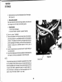
U N IVER SALJOINT
Use a hand greasegun at the Zerk fittingson each crossof the universal
joint. Do not overgreasethese as the seals may be damagedby excess
grease. Use a .l50 weight EP2 automotive chassistype grease,but do not
use a high pressuregun such as that used in a servicestation.
Figure 12
Figure13
Figure 14
Figure 15
THROTTLECABLE
PCVValve
SprayWD40or light weight oil on exposedend of the th rottlecableat the
engine end and work the cable in and out to lubricate.
A positivecrankcaseventilationvalveis locatedon the right hand valve
rocker cover of the engine (leftside on the H320).This valveshould be replaced at leastevery 24 months. (See Figure 15).
BREATHER
FILTER
CRANKCASE
The crankcasebreatherfilter is locatedon the left hand valvecover on
engine models H225,H260,H280,H333and H405.(SeeFigure14).On engine model H320the crankcasebreatherfilter is iocatedon the right hand
17
ENGINE
LUBRICATION
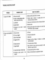
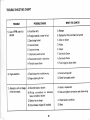
EN GIN EM AINTE NA NCECHA RT
Maintenance Log
Service
F ir s t
10- Hour s
Every
50-Hours
Every
At Least
100-H ours OnceA Year
)han ge e ng ine oil
X
X
X
lha nq e oil f ilter
X
X
X
Every
trme
n spec ft or f uel, oil o r
ruaterleaks
enqrne
is used
X
llean cra nkca seven t f ilt el
X
R ep laceP CV V alv e
l e plac ec ar bur et o r
'u e lf ilt er
X
lheck batterv
X
X
X
X
X
llean batterycables
X
X
llean f lamearrestor
X
X
X
X
X
X
)ooling systemhoses&
:l a m ps
X
l h ec k alt er nat orbe l t te n s i o n
X
X
-u br ic at eU- joint
:n g inet une- up
X
X
18
d,-////////
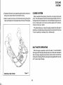
CO O L I N G
SYSTEM
cooling systems'
Hardin enginesare offeredwith three types of engine
engines'
Hardin
'1. Free systemwhich is standardon all
on all Har di n e n g i n e s
2. Re circula tingsystemwhic h is opt ional
3. Th e closed syste mwhic h is opt ional
\
.r''-'.
7--a
\
-
\\\JI
--':
i
Exit
t/
$
engine
\,\ ." From i et dri ve \
N-l
FREESYSTEM
jet
or f r om a n e n g i n ed r l v e n
W at eris su pp liedto th e enginef r omt he dr iv e
w ater p ump wh en cou pledt o a t r ans m ls s lon'
and is preheatedas it
1. Waterentersthe tront of the exhaustmanifold
t
he en g l n e '
t
o
way
t
he
on
m
anif
olds
pa ssesthro ug h the
2. Th ewa terisrou tedf r om t heex haus t m anif o|dt ot he t r o n t c o v e r
the water
plateof the engineand throughthe blockand exitsthrough
do me on to p o f the englne'
is dumped into the ex3. The waterthen passesthroughthe risersand
into the exhaustin the
hausthoseat the rearof the engine'or directly
case of some V-drives.
FRE€ SYSTEM
Figure16
RECIRCULATINGSYSTEM
jet drive' or from an englne
Water is suppliedto the engine lrom the
the engineby a recirculat
through
driven water pump, and is reciiculated
by a thermostatlois
controlled
engine
the
of
temperature
pump.
The
ing
engine'
the
of
caied on the upper front section
is preheatedas it
1. Waterentersthe f ront of the exhaustmanifoldand
engine'
the
to
way
the
on
passesthrough the manifolds
t he engin e ,p a r t i c u l a ra t .
N oT E: Wh en th e je t i St he Sour c eof wat er f or
RPM
oit heeng i n e l f t h e i d l e i s
idle
t
ot
he
giv
en
ten tionsh ou ldbe
RPM in the water)the jet will not develop
set too low loerovigOO
engin e a f t e r a h a r d
the pre ssure r equir ed t o c ool down an
run
the bottomof the
2. The water is routed f rom the exhaustmanifoldto
portionof th(
what
determines
thermostatnouslng The thermostat
at the top of th(
exits
rest
the
and
engine
tne
cJol
to
is
used
water
thermostathousing
engi n es h o u l db e r t r n
Max imumtemp era tur ef or t his engineis 195"F The
t
hr
ot
t
le
full
un
de
r
14
0'F
around
19
COOLING
SYSTEM
3. The water in the block is circulatedthroughthe block by the recirculating pump locatedbelow the thermostathousing.
CLOSED SYSTEM
Water is suppliedto the engineby the jet driveor an englnedrivenwater
pump.This water passeslhroughthe heatexchangerlocatedat the front of
the engineand into the exhaustrisers.The manifoldsand engineare cooled by a closed system much like an automotivesystemwith the heat exchangerworking as a radiator.
4. Water is routed from the top of the thermostathousingthroughthe
risersand dumped into the exhausthose at the reai of the engine.
This system allows you to keep the engine protectedfrom salt water if
operatingin saltwater areasand alsoprotectsfrom sandand dirt build-ups
if you are operatingin extremelysilty or shallowwater.
SALT WATER OPERATING
When the engine is operatedin salt or silty water,it is recommendedto
flush enginewith freshwateraftereach days use.lf salt water is allowedto
stay in the engine,depositsf rom salt build-upand corrosioncould buildup
to the point of shuttingoff the f low of enginecoolingwaterwhich could result in severeengine damage.
RECIRCUI.ATINGSYSTEM
Figure 17
20
COO L I N G
SYSTEM
P R OC E D U R E
FL U S H I N G
1. Disconnecthose at coupling in front of drive unit or installan approved flushing attachmentand connect a garden hose'
a. On Free System run water through system untilwater is clear or
salt free coming out ol the exhaustports'
Flgure18
b.lfRe circula tings y s t em is us ed, t heengines ho u l d b e s t a r t e d a n d
whilef lushingwateris being
run at idle at operatingtemperature,
pass
through the thermostat
to
the
water
applied. This allows
housing and recirculationpump for completeflushing' Do not
run longer than 5 minutes'
2 .|fen gin eh asbe enoper at edins i|t y wat er f or s ev e r a | h o u r s , i t i s a
good practiceto flush the block for sand deposits'
a. With enginerunning,open petcockon the side of the block and
apply flushing water to the engine (See Figure 18)'
plugs in manifold and close engine drain petcocks
-b. Open drain
and apply more flushing water. Manitold drains are located in the
lower rear portion of the manifold (See Figure 19)'
Flgure19
c. tl equippedwith an optionaloil coolerortransmissionoil cooler'
removeplug in cooler and allow water to flush through engine'
(See Figure 20)'
CAUTION: IF BOAT HAS OVER TRANSOM EXHAUST, MAKE SURE
NOSE OF BOAT IS UP. STARTENGINETHEN TURN ON WATER'SHUT
OFF WATER,STOP ENGINE. (JETS ONLY)
Flgure20
21
ELECTRICAL
SYSTEM
The electricalsystem of your Hardin engine consistsprimarily of an
alternator,transistorizedvoltage regulator,batteryand distributor.
BATTERY -73 AMPEREHOUR RATING
ALTERNATOR
Your boat should be equippedwith a 12 volt, minimum73 amperehour
rating battery. Battery cables should be as short as possible. lf the combined length of the positiveand negativecablesis I feet or less,number2
gauge cablesare requiredto enableyou to crank your engine properly.
Periodicallycheck water level in each cell and use only pure distilled
water when replenishingthe supply. Make sure battery is fully charged
when stored below 32oF.This will preventfreezing.
B a t t e r ya c i d s h o u l d b e h a n d l e dw i t h c a r e .l f i t i s sp i l l e do r sp l a sh e do n
any part of the body, immediatelyflush the exposed area liberallywith
waIer.
The Hardin engineis equippedwith a MotorolaMarinealternatorwith a
built in solid-statevoltage regulatorwhich requiresno adiustment.The
output of this alternatoris 37 amperesat 1500RPM and above.Hardinengines which are shipped from the factory prewiredhavea 35 amp circuit
breaker,which protects the electrical system. This breaker is located on
top of the enginebellhousingand should it trip, you may resetit. Shouldit
continue to trip, consult your Hardin AuthorizedDealerto determinethe
cause.
Alternator belt tension may be checked by pressing the belt down midway betweenthe pulleys.Under proper tension,the belt should be displaced about 1/zinch.To tighten belt, loosen the top bolt on the alternator
and the bolt in the sloted bracket
at the bottom and adiust to ProPillitilS er tension and retighten both
bolts. Belt tension should be
checked after the first 10 hours
and several times a season
thereafter.
Keep battery clean, particularlythe top of the battery.Clean by washing
with a solutionof bakingsodaand water,makingsure neithersodasolution
nor water get intothe battery cells.Flushwith cleanwater.A light coat of oil
will help retard corrosion on battery posts.
When connecting a battery, insure that the negative (-) terminal is
grounded. When connecting a booster batteryor charger,make certainthe
connectionsare plus to plus and minus to minus.Failureto do this could
damage the battery.
SPARKPLUGS
fromyourengineuseonlyther+
To obtainthe maximumperformance
commended
sparkplugs.
22
ELECTRICAL
SYSTEM
1. Refer to tune-up chart, page 5, for proper spark plugs for your
eng ine .
2. Remove and inspect each plug for broken, gtazed or blistered insulators.
3. Replaceall plugs which are not serviceable.
4. Be sure ail prugsthat are instailedare of the same makeand number
as other plugs in the engine.
FUEL
SYSTEM
Fuel Pump
An externally vented marine type fuel pump is installed on Hardin
engines.A clear plastic hose is routed from the pump to the f lame arrestor.
lf fuel appearsin this hose,it indicatesthat a malfunctionin the fuel pump
has occurred. consult your Hardin service Dealer as soon as possiblefor
correctiveservice.
Under no circumstancesshould an automotivetype fuel pump be used
on any of the Harclin engines.
Fugl
Filter
A pleated paper filter is installed in the fuel intake fitting ol the quadraiet
carburetor.This f ilter should be replaced once a season,orwhenever it becomes contaminated.This filter will not allow water to pass and will need
replacingshould any water be pickedup. When checkingthe f ilterfor dirt'
inspectthe insideportion of the filter,since the fuel flows from the inside
toward the outside'
A bronze filter is used in the Holley carburetors.This filter should be
washed in carburetorcleanerand blown dry, or replaced'
FUErREQUIREMEIITS
Hardin engines are designedto operateon low-lead or unleadedregular
iuel of 91 octane ResearchMethod or higher'
NoTE:
Road Method
=
87 octane
=
83 octane
91 octane
(Road Method rating is posted on gas pumps)'
Research Method
Motor Method
GasolineContainingAlcoholor Gasohol
in your HardinEngine
The useof Gasoholis not recommended
23
F U EL
SYSTEM
,
GarburetorAdjustments
The carburetor has been adjusted at the factory and should not need
adjusting.However,changein f uel,altitudeand climatemay makeit necessary to re-adjust.
ldle Mixture
With the engine at operatingtemperatureand at idle RPM, adjust idle
mixture.
Turn adjustmentscrew 1/tlurnal a time until the maximumRPM is indicated on the tachometer.
HOLLEY CARBURETOR
Figure 20
ur
',
ldle Speed
After both idle mixtureshave been adjustedon enginescoupledto jet
drive,adjustthe idle RPMto 900 RPM if the boat is in thewater.On engines
coupledto transmissionset idle RPMto 850RPMin neutral.lnsurethatthe
choke is fully open beforesetting idle RPM.
QUADRAJET
CARBURETOR
Figure21
24
TROUBLE SHOOTING CHART
TROUBLE
1. Enginewill not crank
2. Enginecranks trrt will not
start.
WHAT YOU CAN DO
POSSIBLECAUSE
C. Low Battery
A. Makesureshift control leveris in neutral
B. Tighten cables on battery. lf corroded,clean as describedunderElectricalSystem'
C. Check level of electrolyteand refer to ElectricalSystem
D. lgnition Switch
D. Replaceswitch
A. Neutral start switch
B. Loose or corroded battery cables
and/or wiring harnessPlug.
E. Hydrostatic Lock (water in engine
cylinder)
E. Removespark plugsand turn engineover by hand' See
HardinDealerif engineis damaged
A. Empty fuel tank
A . Fi l l tank
B. Tank vent clogged
B. Freevent of obstruction
C. Shut off valveclosed
D. Cloggedfuel filter
C. Openvalve
E. Chokestuck oPen
E. Freechokevalveand linkage
F. Open-throttle full oPen and do
enginefor at least5 minutes
D. Inspect fuel filter. Replace,if necessaryas outlined
under Fuel System
F. Engineflooded
G. Fouledsparkplugsor impropergap
H. Distributor points burned or misadjusted
25
attempt
G. Inspectsparkplugs,Cleanor replace
of points
H. Seeyour HardinDealerfor replacement
T RO UB L ES HO O T I N GC H A R T
T RO UB LE
ldles rou gh o r misseswhile
idling
4 . E n gin e he sita tes on ac cele ratio n or slu gg is h
P O S SIB L EC A U S E
W H A T Y OU C A N D O
A. ldle s peed low
A. Adjust idle to specifications
B. Vac uum leak s
B . C o r r e c t l e a k s i n h o s e s ; i n t a k e m a n i fo l d o r ca r b u r e to r
mounting bolts.
C. Spar k plugs f ouled
C. Clean or replace
D. M os it ur e or c r ac ks i n d i s t r i b u t o r c a p
D. Cleanor replace
E. Bur ned or s t ic k ing v a l v e s
E. SeeHardin Dealer
F. I nc or r ec t dis t r ibut o r a d v a n c e o r p o i n t
dwell
F. Adjust or seeHardin Dealer
G . I nc or r ec t idle m ix tu r e
G. A dj ust
A. Fuel f ilt er dir t y
A , R e p l a c ef i l t e r
B. Ac c eler at or pum p i n o p e r a t i v e
B . H a v e H a r d i n D e a l e rc h e c k
C. I nc or r ec t dis t r ibuto r a d v a n c e o r p o i n t
dwell
D . H a v e H a r d i n D e a l e rc h e c k
D. lgnit ion c oil bad
E. lgnit ion wir ing c r a c k e d
wir e ends .
Adjust or seeHardin Dealer
corroded
E. Cleanor replace
F. Spar k plugs f oul- d
F. Cleanor replace.
G . Thr ot t le not f ully o p e n e d
G. Adjust throttle cable
26
'1
-t
TROUBLE SHOOTING CHART
TROUBLE
5. Lossof RPMunderfull
throttle
6. Enginebackfires
WHAT YOU CAN DO
POSSIBLE CAUSE
A. Fuelfilter dirty
A. Replace
B. Foreignmaterialor water in fuel
B. Replacefuel filter and cleanfuel system
C. Sparkplugsfouled
C. Cleanor replace
D. Incorrectdwell
D. Adiust
E. Incorrecttiming
E. Adiust
F. DistributorPointsburned
G. Stuck powerpistonin carburetor
F. SeeHardinDealer
G. S eeH ardi nD eal er
H. Partiallyclosedchoke
H. Freelinkageor adiustchoke
A. Sparkplugwiresinstalledwrong
A. Correctwiring order
B. Enginestarvingfor fuel
B. Checkfuel suPPlYsystem
7. Alternatorwill not charge A. Drive belt looseor broken
or haslow output.
B . Wi ri n g c o n necti ons on al ternator
loose,corrodedor broken
A. Adust or replacebelt
B. Cleanand tightenconnectionsand checkwiring
C. Battery hasno charge
C. Checkbatteryconditions
D. Circuitbreakertripped (if installed)
D. Reset
n
W IN T ER
STORAG
WINTERSTORAGE
a. Free System
Long periodsof storagecan adverselyeffect the internalpartsof your
engine unlessmethodsof preservationare used.Your HardinAuthorized
Dealeris equippedto providethis servicefor you.
1. Removethe hosesfrom the water inlet manifolddome on tcp
of the engine.See Figure 22. This will preventvacuum frorr
holding water in the block.
2. Remove plugs on port and starboardmanifolds.See Figure
23.
The following procedureswill give you maximum protection:
1. Warm up engineto normaloperating temperature with coolingwater
flowing through engine.
L
Change engine oil and filter - See LubricationSystem.
Run enginea few rninutesto distributefreshoil throughoutengine.
Shut off engine and check oil levelto insure it is at the full nrark.
4. Shut off fuel supply and removeand clean flame arrestor.
Startengineand run a fast idle of 100G1200RPMwhileslowlypouring 1 cup of SAE 20W oil (or rust preventativefor this use) into the
carburetorwhile the fuel in the carburetor and fuel line is being
burned.Stallthe engineby dumpingthe lastfew ouncesrapidlyinto
the carburetor.Turn ignition off and replaceflame arrestor.
6. Drain fuel from fuel tanks to preventgumming of the fuel.
7. Loosen alternatorbelt.
8. Flush engine- see FlushingProcedures.
&.,
-13
Figute 22
lf a sand or silt depositis allowedto remainin the block for an extended
period of time, it may becomeimportantto flushthe engineprior to lay-up
ratherthan after the lay-up period.
9. Drain engine to protect from freezingduring storage.Hardin does
not recommenddrainingyour engine with the boat in the water.A
50o/omixture of antifreeze and water may be added to all systems
after drainingto help minimizethe chance of freezing.
ExhaustManitold
Drain Plug
Figure23
28
WINTER
ST O R AG E
3. Open pelcockson port and starboardside of the engine'
See Figu re 24.
b. Recirculating SYstem
Same as above plus disconnectlarge water pump hose and
cra nk en gin e ov er t o em pt y r ec ir c ulat ingpum p .
c. Closed SYstem
1 . Drain he at ex c hanger s .
2. Add anti-treezeto system to preventfreezing'
10 . Dra in oil coo ler , if ins t alled.
11. Removethe batteryfrom the boat,clean posts,checkelectrolyte level and store in a ventilatedareathat is not exposedto
children.The batteryshould be fully chargedwhen storedto
preventdamagetrom freezing,and should be rechargedperiodically if stored for an extended period of time (over 3
mon ths).
1 2. Co al all e ng ineelec t r ic alc onnec t ionswit h a lig h t c o a t i n go f
rust Preventative.
13. Cover the intakearea of the flame arrestorand exhaustports
with tap e to m inim iz ec ondens at ionins idet he e n g i n e
N O TE:
Block Drain
The precedingprocedureis intendedfor preparationofyour boat
for dry storage.Hardin Marine does not recommend leavinga
Hard ineq uip pe dboat in t hewat er f or an ex t endedp e r i o d o ft i m e
if you do not intend to operatethe boat on a regular basis For
more inlo rmatio non leav ingy our Har din equippe db o a t i n t h e
wate r, co nsult the Har din dealer in y our ar ea.
29
RETUR NEN GIN E
FORSERVICE
PREPARATION
OF ENGINEFORSERVICE
1. Close petcock drains; 1 port side and 1 starboard side of the
block.
7. Remove tape from flame arrestor and exhaust ports.
8. Removespark plugs. Clean and gap, crank engine over for 15
seconds to insure all reciprocating parts are free, and fresh oil is
being pumped throughout the engine. lnstall spark plugs, and
take care to connect plug wires in proper order.
Replacedrain plugs - 1 port side and 1 starboardside ol manifolds.
e
Replaceplug in oil cooler if oil cooler is used.
9. Installnew carburetorfuel filter.
'10. Check engineand drivefor any foreignobjects;loosenuts,etc. . ,
'11. Air out engine compartntentthoroughly and start engine.See
4. Connect water hoses and check all hose connections.
l.
Clean batteryend of cablesand installfully chargedbattery.Insure positivecable is connected to positive post. Apply light coat
of oil to battery post.
engine starting procedureson page 10.
Fill fuel tank with fresh fuel and turn fuel valveon.
,J
30
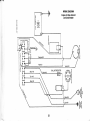
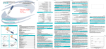
IN S TR U ME N T WIR IN G A MME TE R
@
el
;i
!1
9'
,i,
";l
Ft
2t
*l
ACC SW ITCHES
dl
Fr
j us"
!
o
t
[J
:1
--'r ;
r aoc 20-L_
(
I
Fuse
AGC 1O
31
Y erw /R r1o
llo
.'
T-
Blue#16 Instr um ent L
INSTRUMENTWIRINGVOLT METER
Acc. Switches
NOTE:
1. This diagramdepictsvoltmeterusage.The use of the old style ammeteris not recommended.
2. Do not connect12 volt powersourceto any "s" terminal.
3. Do not connectany wire to voltmeter"s" terminal.
4. Hardintachs may be usedfor 4,6 or I cylinderengines,Insurejumperwire is connectedto properpin.
5. Theseinstrumentsare compatiblewith all Hardinengines.
WIR IN G D IA GR A M
B
It
Engine wilh Slave Solenoid
and Circuil Breaker
-t
i
s:
o
o
c
=
m
x
m
BALLASTRESISTOB
mm
z ui O
vvlML
m
*-€
2 n >.
33
IMPORTANTFACTS ABOUT YOUR WARRANTY
1. A War ran lyFormisse nt wit hlheengineand/ or dr iv e. Th i s l o r m m u s t b e f i l l e d o u t b y y o u a n d y o u r d e a l e r a n d s e n t t o H a r d i n Ma r i n e fo r
product regislralion within 10 days of purchase. A Warranty Card will then be sent to you.
2' A Warranty Card musl b€ presented to a Hardin Marine Aulhorized Dealer before any warranty service is begun.
3. The englne musl be deliveredto a Hardin Marine Authorized Dealer'splace of businessduring regular businesshours for warranly
repairs.
The following ilems are not covered by the warranty:
a. Normaltune-up (points,plugs,condenser,carburetoradjustments,or wiring).
b. Malfunctionsdue to impropermaintenanceor lack of maintenance.
c. Additionalservicework which is requestedby you that is not
.necessaryto repair the defect.
d. Damagefrom use of lower octane fuel than that specifiedor
use of contaminatedfuel.
e. Damage to the engine electrical system due to incorrect
wiring of harness,instrumentpanel or electricalequipment
not provided by Hardin Marine.
f. Damageto engine from submersionor freezing.
g. Damage from water reentering engine through exhaust
svstem.
Engine failure from excessiveRPM.
Engines used for racing, or subiect to accident neglect,
alterationsor imporper installations.
Repairsfor normal wear, rust or corrosion,or failure of nonauthorizedoarts.
P i c k - u pa n d d e l i v e r yo f b o a t ;m e c h a n i c 'st r a v e l ,t i me ,o r h a u l out charge.
Subsequentowners are not covered under the warranty.
Basically,this warranty is designedto protecl you trom bearinglhe cosl of repair of a Hardin engine,drive unil or lrans where lhat repair is
caused by Hardin's neglect. This wartanty is not deslgned to protect you if your engine is not maintained and operaled properly.
H A R D IN .MA R IN E
LIMITEDENGINEWARRANTY
delectsin materialand workmanship'
1. HardinMarinewarrants,to the firstoriginalretailpurchaser,each new engineassemblymanufacluredby HardinMarineto be free trom
2'The w a f r a n t y p e r i o d sh a | | co m m e n ce o n th e d a te th e p r o d u c ti sfi rstp|acedi nservi ce,orth{dateofpurchasebytheJi rstretai |purchaser' w hi c heV
erc omes fi rs t,3l 9..
be effectivelor a periodof 90 days
continuefor a periodof one year from that date undei normal,non commercialuse. In the Caseof commercialuse, this warrantyshall
periodof three monthstrom the datg
for
a
shall
be
H425
oS
model
warranty
on
engine
limited
purchaser.
Marine's
Hardin
purchase
retail
the
originat
ny
from the date of
of original retailpurchase.
to the purchaser'sresidence,the address
3. Claimsunder this warrantyshall be made by returningthe defectivepart to an authorizedservicedealerof HardinMarinenearest
HardinMarinewill not pay for iabor
of which will be furnlshedby HardinMarineupon yori r"qre"t, or by returningthe defectivepart to HardinMarineat the addressbelow.
and/or materialsfurnishedby other than Hardin Marineor its authorizedservicedealers.
periodwill be repairedor replaced,at HardinMarine'soption,
4. Any productdeterminedby HardinMarineto be defectivein eithermaterialor workmanshipduringthe warranty
parts found to be defectiveduring the warrantyperiod'
iepairing
or
replacing
to
be
limited
shall
hereunder
liability
Marine's
parts
Hardin
or
labor.
for
without charge
product
without
assuming any obligalion to modify any such units
Hardin
Marine
5. Hardin Marine reserves the right to change or improve the design of any
previouslymanufactured.
EXCLUSIONSAND LIMITATIONS
This warrantydoes not apply to:
warrantyhas beensuppliedto the consumerby the respectivemanufacturer'
by HardinMarine,and for whicha manutacturer's
1, Any part,accessoryor produ;t not manufactured
resull of normalwear and tear.
necessary
as
a
2. Normal maintenanceitems such as tune-up,lubrication,filtersand adjustments
Hardin
Marine;
than
other
repaired
by
or
altered,
modified,
part
has
been
which
or
3. Any engine assembly
suppliedwith each new Hardin Marine
which are not suitablefor use with the engi-ne,failuie to operateand.maintai;the productin accordancewith the owner'smanual
the engine at RPM in
product,productsused for racing,damage resultingtrom water or other substancesenteringthroughthe exhaustmanifoldor carburetor,operating
material,or assemblyof a HardinMarineProduct'
excessof the maximumratedRpM as statedin the owner'smanual,or any cause otherthan i defeci in the manufacture,
cost
incidental,consequentialor other damageswhatsoever,includingbut not limitedto: loss of use, loss of time, inconvenience,
5,
- HardinMarineshall not be liablefor any
loss or damage to personalproperty'
lodging,
or
Hardin
Marine,
travel,
dealeior
Marine
service
Hardin
proouct
ro
an
authorized
o"ie"iiu"
;i;;i;r;i;gfi"
not apply to you.
6. Some statesdo not ailow the excluslonot limitationof incidentalor consequentialdamages,so the above limitationsmay
and fitnesstor a parlicutarpuipor.. nrt impiiio warrantiesare limitedin durationto the minimumperiodrequiredby state law.
any other personto assume for it any other liability-orwarrantyin connectionwith its products.
on the durationof impliedwarranties,so the above limitationmay not appl-vto you
a Sor" statesdb not allow timitations
rights,and you may also have other rightswhich may Varyfrnnl stateto state
you
legal
gives
specilic
warranty
This
9.
H A R D INMA R IN E ,IN C .
1711S. ClaudinaWay,Anaheim,California92995 o (714)956-9100
HardinMarineneithe,assumesnor authorizes
BPI Revised1/88
Printedin U.S.A.