1
_6
Operator's Manual
CRRFTSMRN_
1.4 cu. in./21cc 2-Cycle / .065 In. Line
16 Inch Cutting Path
®
GASOLINE WEEDWACKER
Model No.
358.798520
WARNING:
Read and follow all Safety Rules and Operating
Instructions before first use of this product.
For answers to your questions about this product:
Call 7 am-7 pm, Mon-Sat; Sun, 10 am-7 pm
1-800-235-5878
Sears, Roebuck and Co., Hoffman Estates IL 60179 USA
530..084025
3/13/96
H
H
H
H
H
Warranty Statement
Safety Rules
Assembly
Operation
Maintenance
2
2
4
5
8
Service & Adjustments
Storage
Troubleshooting Chart
Spanish
Parts and Ordering
9
11
12
16
Back
FULL ONE YEAR WARRANTY ON CRAFTSMAN GAS POWERED
WEEDWACKER ® LINE TRIMMER.
For one year from the date of purchase, when this Craftsman Gas Powered
Weedwacker® Line Trimmer is maintained, lubricated, and tuned up according to
the operating and maintenance instructions in the operator's manual, Sears will
repair, free of charge, any defect in material or workmanship.
This warranty excludes nylon line, spark plug, and air filter, which are expendable
parts and become worn during normal use.
If this Weedwacker® Line Trimmer is used for commercial purposes, this warranty
applies for only 90 days from the date of purchase. If this Weedwacker® Line Trimmer is used for rental purposes, this warranty applies for only 30 days from the date
of purchase. This warranty applies only while this product is in use in the United
States.
WARRANTY SERVICE IS AVAILABLE BY RETURNING THE WEEDWACKER®
LINE
TRIMMER TO THE NEAREST SEARS SERVICE CENTER IN THE UNITED STATES.
This warranty gives you specific legal rights, and you may also have other rights
which vary from state to state.
Sears, Roebuck
and Co. Dept. D/817WA Hoffman
WARNING:
When using gardening
appliances, basic safety precautions
must always be followed to reduce the
risk of fire and serious injury Read and
follow all instructions
This power unit can be dangerous!
Ooeretor is responsible for following
instructions and warnings on unit and
in manual. Read entire Operator's
Manual before using unit! Be thoroughly familiar with the controls and the
proper use of the unit. Restrict the use
of this unit to persons who have read,
understand, and will follow the instructions and warnings on the unit and in
lhe manual. Never allow children to
operate this unit.
Estates, IL 60179
Safety information on the unit
DANGER: Never use blades or flailing
devices. This unit is designed for line
trimmer use only. Use of any other accessories or attachments will increase
the risk of injury.
000
WARNING: Trimmerline throwsobjects violently. Youand otherscan be
blinded/injured.Wear eye and leg
• Move at least 10 feet (3 meters)
away from fueling site before starting
engine.
• Stop engine and allow to cool before
removing fue] cap.
CUTTING SAFETY
• Use only for trimming, mowing, edging, and sweeping. Do not use for
pruning or hedge trimming.
• Inspect the area before each use.
Remove objects (rocks, broken
glass, nails, wire, etc.) which can be
thrown by or become entangled in
line. Hard objects can damage the
trimmer head and be thrown causing
serious injury.
• Keep firm footing and balance. Do
not overreach.
• Keep all pads of your body away
from muffler and spinning line. Keep
engine below waist level. A hot muffler can cause serious burns.
• Cutting on left side of the shield will
throw debris away from the operator.
TRANSPORTING
AND STORAGE
• Allow engine to cool; secure unit before storing or transporting in vehicle.
• Empty the fuel tank before storing or
transporting the unit. Use up fuel left
in the carburetor by starling the engine and letting it run until it stops.
• Store unit and fuel in area where fuel
vapors cannot reach sparks or open
flames from water heaters, electric
motors or switches, furnaces, etc.
• Store unit so line limiter cannot accidentally cause injury. The unit can be
hung by the tube.
• Store unit out of reach of children.
• If situations occur which are not covered in this manual, use care and
good judgment. If you need assistance, call 1-800-235-5878.
• If situations occur which are not covered in this manual, use care and
good judgement, ff you need assistance, contact Sears Service or call
f-800-235-5878.
OPERATOR
SAFETY
• Always wear safety eye protection.
• Always wear long pants, long
sleeves, boots, and gloves. Wearing
safety tog guards is recommended.
Do not go barefoot or wear sandals.
Stay clear of spinning line.
• Secure hair above shoulder length.
Secure or remove loose clothing or
clothing with loosely hanging ties,
straps, tassels, etc. They can be
caught in moving parts,
• Do not operate when you are tired,
ill, or under the influence of alcohol,
drugs, or medication.
• Wear hearing protection if you use
unit for more than 1-1/2 hours per
day.
• Never start or run inside a closed
room or building. Breathing exhaust
fumes can kill.
• Keep handles free of oil and fuel.
UNIT / MAINTENANCE
SAFETY
• Disconnect the spark plug before
performing maintenance except carburetor adjustments.
• Look for and replace damaged or
loose parts before each use. Look
for and repair fuel leaks before use.
Keep in good working condition.
• Replace trimmer head parts that are
chipped, cracked, broken, or damaged in any other way before using
the unit.
• Make sure unit is assembled correctly as shown in this manual.
• Make carburetor adjustments with
rower end supported to prevent line
from contacting any object.
• Keep others away when making carburetor adjustments.
• Use only recommended Craftsman
accessories and replacement parts.
FUEL SAFETY
• Mix and pour fuel outdoors.
• Keep away from sparks or flames.
• Use a container approved for fuel.
• Do not smoke or allow smoking near
fuel or the unit.
• Wipe up all fue! spills.
SPECIAL
NOTICE: This unit is not
equipped with a temperature limiting
muffler and spark arresting screen
which meets the requirements of California Codes 4442 and 4443. All U.S.
forest land and the states of California,
Idaho. Maine. Minnesota, New Jersey,
Oregon, and Washington require by
law that many internal combustion engines be equipped with a spark arrestor screen. If you operate in a locale
where such regulations exist, you are
3
legally
responsible for installing and
maintaining the operating condition of
these parts. Failure to do so is a violation of the law, Refer to the MAINTENANCE section in this manual.
vessel damage in otherwise healthy
people. If symptoms occur such as
numbness, pain, loss of strength,
change in skin color or texture, or loss
of feeling in the fingers, hands, or
joints, discontinue the use of this tool
and seek medical attention. An antivibration system does not guarantee
the avoidance of these problems. Users who operate power tools on a continual and regular basis must monitor
closely their physical condition and the
condition of this tool.
SPECIAL
NOTICE: Exposure to
vibrations through prolonged use of
gasoline powered hand tools could
cause blood vessel or nerve damage
in the fingers, hands, and joints of
people prone to circulation disorders or
abnormal swellings. Prolonged use in
cold weather has been linked to blood
CARTON
CONTENTS
ADJUSTING
THE HANDLE
WARNING:
When adjusting the handle, be sure if remains between the
trigger and the safety label.
• Loosen wing nut or knob on handle.
• Rotate the handle on the tube to an
upright position; retighten wing nut.
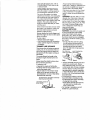
ATTACHING
SHIELD
WARNING: The shield must be properly
instalred.The shield provides partia!
protection from the risk of thrown objects
to the operator and others and is
equipped with a line limiter which cuts
excess line to the proper length. The line
limiter {on underside of shield) is sharp
and can cut you. For proper orientation.
see illustration in Operation section.
• Remove wing nut from shield
• Insert bracket into slot as shown.
• Pivot shield until bolt Dasses through
hole in bracket.
• Securely tighten wing nut onto bolt.
Check carton contents against the following list.
Model 358.798520
• Trimmer
• Shield
• Container of Oil
Examine parts for damage. Do not use
damaged parts.
NOTE: II you need assistance or find
parts missing or damaged, call
1-800-235-5878.
It is normal for the fuel filter to rattle in
the empty fuel tank.
Finding fuel or oil residue on muffler is
normal due to carburetor adjustments
and testing done by the manufacturer.
ASSEMBLY
WARNING:
If received assembled,
repeat all steps to ensure your unit is
properly assembled and all fasteners
are secure.
Slot
/
Bracket
/
_
4
Wing
Nut
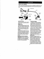
KNOW YOUR TRIMMER
READ THIS OPERATOR'S MANUAL AND SAFETY RULES BEFORE OPERATING YOUR
UNIT, Compare the illustrations with your unit to familiarize yourself with the location of the various controls and adjustments. Save this manual for future reference.
Assist Handle
Tube
On/Stop
Switch
_Thro_le
Trimmer
Head
Starter
Rope
Choke
Lever
Debris
Shield
Line
Primer
Bulb
Fuel Mix
Fill Cap
ON/STOP SWITCH
The On/Stop switch is used to stop the
engine. Press and hold the switch to
stop the unit.
PRIMER BULB
The primer bulb removes air from the
fuel lines and fills them with fuel. This
allows you to start the engine with fewer pulls on the starter rope. Activate
the primer bulb by pressing it and alPowing it to return to its original form.
CHOKE
The choke helps to supply fuel to the
carburetor during starting. This allows
you to start a cold engine. Activate the
choke by moving the choke lever to
the Full position. After the engine has
started, move the choke to the Off
position.
BEFORE STARTING
ENGINE
_r,......._._ Limiter
Blade
FUELING ENGINE
This engine is certified to operate on
unleaded gasoline. Before operation,
gasoline must be mixed with a good
quality 2-cycle air-cooled engine oil
We recommend Craftsman brand oil.
Mix gasoline and oil at a ratio of 40:1
{A 40:1 ratio is obtained by mixing 3.2
ounces of oil with 1 gallon of unleaded
gasoline). DO NOT USE automotive oil
or boat oil. These oils will cause
engine damage. When mixing fuel.
follow instructions printed on container.
Once oil is added to gasoline, shake
container momentarily to assure that
the fuel is thoroughly mixed. Always
read and follow the safety rules
relating to fuel before fueling your unit.
IMPORTANT
Experience indicates that alcohol
blended fuels (called gasohol or using
ethanol or methanoil can attract moisture which leads to separation and
formation of acids during storage.
Acidic gas can damage the fuel systern of an engine while in storage.
To avoid engine problems, empty the
fuel system before storage for 30 days
or longer. Drain the gas tank, start the
engine and let it run until the fuel lines
WARNING:
Be sure to read the fuel
information in the safety rules before
you begin. If you do not understand
the safety rules, do not attempt to fuel
your unit. Call 1-800-235-5878,
5
andcarburetor
areempty.
Usefresh
fuelnextseason.
Neveruseengine or carburetor cleaner products in the fuel tank or permanent damage may occur.
See the STORAGE section for additional information.
STOPPING
YOUR
ENGINE
• Press and hold the On/Stop switch in
the STOP position.
• If engine does not stop, move choke
to the Full Choke position.
Choke Lever
Engine
Stoe
STARTING
YOUR
ENGINE
COLD ENGINE OR WARM ENGINE
AFTER RUNNING OUT OF FUEL
WARNING:
The trimmer head will
turn while starting the engine.
Avoid any contact with the muffler. A
hot muffler can cause serious burns.
NOTE: If the engine sounds as if it is
trying to start before the 5 th pull, go to
the next step.
• Move the choke lever to the Half
Choke position.
• Pull stader rope sharply until engine
runs, but no more than 6 pulls.
NOTE: if the engine has not started
after 6 pulls (at half choke), check to
make sure the choke lever is in the
proper position. Then, move the choke
lever to the Full Choke position and
press the primer bulb 6 times; squeeze
and hold the throttle trigger and pull
the starter rope 2 more times. Move
the choke lever to Half Choke and Dull
the starter rope until the engine runs.
but no more than 6 more Dulls. If the
engine still has not started, it is probably flooded. Proceed to "Starting a
Flooded Engine."
• Allow the engine to run 10 seconds
then move the choke lever to Off
Choke. Allow the unit to run for 30
more seconds at Off Choke before
releasing the throttle trigger.
NOTE: If engine dies with the choke
lever at the Off Choke position, move
the choke lever to Half Choke and pull
the rope until engine runs.
STARTING A WARM ENGINE
• Rest engine and shield on ground,
supporting trimmer head off ground.
• Move the choke lever to the Full
Choke position.
• Slowly press the primer bulb 6 times.
• Squeeze and hold the throttle trigger.
Keep throttle trigger fully squeezed
until the engine runs smoothly.
Choke Lever
• Pull starter rope sharply 5 times.
• Move the choke lever to the Half
Choke position.
• Squeeze and hold the throttle trigger.
Keep throttle trigger fully squeezed
until the engine runs smoothiy.
• Pull starter rope sharply until engine
runs. but no more than 5 pulls
• Allow engine to run 15 seconds,
then move the choke lever to Off
Choke,
NOTE: if engine has not started, pull
starter rope 5 more pulls. If engine still
does not run. it is probably flooded.
DIFFICULT STARTING OR
STARTING A FLOODED ENGINE
Flooded engines can be started by
placing the choke lever in the Off
Choke position; then, pull the rope to
clear the engine of excess fuel. This
could require pulling the starter handle
many times depending on how badly
the unit is flooded.
Iftheunitstilldoesn't
start,referto
TROUBLESHOOTING
chartorcall
1-800-235-5878.
OPERATING
Always tap the trimmer head on a
grassy area. Tapping on surfaces such
as concrete or asphalt can cause excessive wear to the trimmer head.
INSTRUCTIONS
If the line is worn down to 2 in. (5 cm)
or less, more than one tap will be required to obtain the most efficient line
length.
WARNING:
Use only .065" (1.6 mm)
diameter line. Other sizes of line will
not advance properly and can cause
serious injury. Do not use other materials such as wire, string, rope, etc. Wire
can break off during cutting and become a dangerous missile that can
cause serious injury.
CUTTING METHODS
Bring the engine to cutting speed before entering the material to be cut.
Do not run the engine at a higher
speed than necessary, The cutting line
will cut efficiently when the engine is
run at less than full throttle. At lower
speeds, there is less engine noise and
vibration. The cutting line will last
longer and will be less likely to "weld"
onto the spool.
If the trimmer head does not turn when
the engine is in operation, make sure
the drive shaft housing is properly
seated in engine shroud.
Always release the throttle trigger and
allow the engine to return to idle speed
when not cutting.
To stop engine:
• Release the throttle trigger.
• Push and hold down the momentary
switch until the engine has stopped
completely.
TRIMMER
WARNING: Use minimum speed and
do not crowd the line when cutting
around hard objects (rock, gravel,
fence posts, etc.), which can damage
the trimmer head, become entangled
in the line, or be thrown causing a serious hazard.
• The tip of the line does the cutting.
You will achieve the best performance and minimum line wear by not
crowding the line into the cutting
area. The right and wrong ways are
shown below.
LINE ADVANCE
The trimmer line will advance approximately 2 in. (5 cm) each time the bottom of the trimmer head is tapped on
the ground with the engine running at
full throttle.
Tip of the Line
DoesThe Cutting
The most efficient line length is the
maximum length allowed by the line
limiter.
Right
Always keep the shield in place when
the tool is being operated.
To Advance Line:
• Operate the engine at full throttle.
• Hold the trimmer head parallel to and
above the grassy area.
• Tap the bottom of the trimmer head
lightly on the ground one time. Approximately 2 in. (5 cm) of line will be
advanced with each tap.
Line Crowded Into
Work Area
"_'-"_"." Wrong
-'
• The line will easily remove grass and
weeds from around walls, fences,
trees and flower beds. but it also can
cut the tender bark of trees or shrubs
and scar fences. To help avoid damage especially to delicate vegetation
or trees with tender bark. shorten line
to 4-5 in. (10-13 cm] and use at less
than full throttle.
• For trimming or scalping, use less
than full throttle to increase line life
and decrease head wear, especially:
• During light duty cutting.
• Near objects around which the line
can wrap such as small posts.
trees or fence wire.
For mowing or sweeping, use full
throttle for a good clean job.
Toadvance line. tap bottom of tdmmer
head on ground one time.
proper length.
7
WARNING;
Always
weareyeprotection.Neverleanoverthetrimmer
head.
Rocks
ordebriscanricochet
orbe
thrown
intoeyesandfaceandcause
blindness
orotherserious
injury.
TRIMMING
- Holdthebottom
ofthe
trimmer
headabout
3 in.(8cm)above
theground
andatan angle. Allow only
the tip of the line to make contact. Do
not force trimmer line into work area.
Trimm
3 in. (8 cm)
Above Ground
Mowing
I_
._
_"_'_Ql_\
_
"'_
SWEEPING - The fanning action of
the rotating line can be used for a
quick and easy clean up. Keep the line
parallel to and above the surfaces being swept and move the tool from side
to side.
SCALPING - The scalping technique
removes unwanted vegetation. Hold
the bottom of the trimmer head about 3
in. (8 cm) above the ground and at an
angle. Allow the tip of the line to strike
the ground around trees, posts, monuments, etc. This technique increases
line wear,
Scalping
MOWING - Your trimmer is ideal for
mowing in places conventional lawn
mowers cannot reach. In the mowing
position, keep the line parallel to the
ground. Avoid pressing the head into
the ground as this can scalp the
ground and damage the tool.
...........
Sweeping
,
MAINTENANCESCHEDULE
Check for Loose fasteners and parts
Check for damaged or worn parts
Clean unit and labels
WHEN TO PERFORM
Before each use
Before each use
After each use
Clean air filter
Every 5 hours of operation
Inspect and clean spark arrestor
Replace spark plug
Every 25 hours of operation
Yearly
CARE & MAINTENANCE
TASK
CHECK FOR LOOSE
FASTENERS
AND PARTS
• Spark Plug Boot
• Air Filter
• Housing Screws
• Assist Handle Screws
• Debris Shield
GENERALRECOMMENDATIONS
The warranty on this unit does not cover items that have been subjected to
operator abuse or negligence. To receive full value from the warranty, the
operator must maintain unit as instructed in this manual. Various adjustments
wil! need to be made periodically to
properly maintain your unit.
8
CHECK FOR DAMAGED
WORN PARTS
• Wash the filter in soap and water,
• Allow filter to dry.
• Replace parrs.
OR
Refer replacement of damaged/worn
parrs to your Sears Service Center.
• On/Stop Switch - Ensure On/Stop
switch functions properly by moving
the switch to the "Stop" position.
Make sure engine stops; then restart
engine and continue.
• Fuel Tank - Discontinue use of unit if
fuel tank shows signs of damage or
leaks.
• Debris Shield - Discontinue use of
unit if debris shield is damaged.
Air Fi_ter
crews
J
Cove_
INSPECT AND CLEAN SPARK
ARRESTOR
(if equipped)
As the unit is used, carbon deposits
build up on the muffler and spark
arrestor screen, and must be removed
to avoid creating a fire hazard or affecting engine performance.
Remove the spark arrestor screen
from the muffler and clean. Replace
spark arrestor screen if breaks occur.
CLEAN UNIT & LABELS
• Clean the unit using a damp cloth
with a mild detergent.
• Wipe off unit with a clean dry cloth.
CLEAN AIR FILTER
Do not clean filter in gasoline or other
flammable solvent to avoid creating a
fire hazard or producing harmful evaporative emissions.
REPLACE
REPLACING
THE LINE
• Remove the spool by firmly pulling on
the tap button.
• Clean entire surface of hub and spool.
• Replace with a preowound spool, or
cut a length of 20 feet of.065" (1.6 mm)
diameter Craftsman ® brand line. Never use wire, rope, stdng, etc., which
can break off and become a dangerous missile.
• Insert one end of the line about 1/2
inch (1 cm) into the small hole inside
the spool
• Wind the line evenly and tightly onto
the spool. Wind in the direction of the
arrow found on the spool.
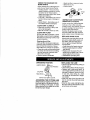
POSITION
ALWAYSWEAR:
PLUG
Replace the spark plug each year to
ensure the engine starts easier and
runs better. Set spark plug gap at
.025 in. Ignition timing is fixed and
nonadjustable.
• Twist, then pull off spark plug boot.
• Remove spark plug from cylinder
and discard.
• Replace with Champion RCJ-8Y
spark plug and tighten with a 3/4 in.
socket wrench (10-12 ft.-Ibs).
• Reinstall the spark plug boot.
Cleaning the air filter:
A didy air filter decreases engine performance and increases fuel consumption and harmful emissions. Always
clean after every 5 hours of operation,
• Clean the cover and the area around
it to keep dirt and debris from falling
inte the carburetor chamber when
the cover is removed.
• Remove parts as illustrated.
OPERATING
SPARK
"_
Eye Protection
Long Pan_
Heavy Shoes
Cut from your right to your left.
ADVANCING
THE CUTTING LINE
Advance line by tapping bottom of cutting head lightly on the ground while engine is running at full speed. A metal
blade attached to the shield wilt cut the
line to the proper length.
9
• Push the line into the notch, leaving 3
to 5 inches (7 - 12 cm) unwound.
• Insert the line into the exit hole in the
hub as shown in the irlustration.
• Align the notch with the line exit hole.
• Push the spool into the hub until it
snaps into place.
• Pull the line extending outside the hub
to release it from the notch.
Small
.e,°
sped,
'°nte
Hub
Line exit hole
CARBURETOR ADJUSTMENT
WARNING: The trimmer head will be
spinning during most of this procedure
Wear your protective equipment and
observe all safety precautions. After
making mixture adjustments, recheck
idle speed.
Carburetor adjustment is critical and if
done impropeny can permanently
damage the engine as well as the carburetor. If you reqmre further assrstance or are unsure about pedorming
this procedure, carl our customer assistance help line at 1-800-235-5878.
Old fuel. a dirty air tilter, a dirty fuel filter. or flooding may give the impression of an improperly adjusted carburetor. Check these conditions before
adjusting the carburetor.
]'he carburetor has been carefully set
at the factory. Adjustments may be
necessary if you notice any of the following conditions:
• Engine will not idle. See "Idle Speed"
under adjusting procedure.
• Engine dies or hesitates instead of
accelerating. See "Acceleration
Check" under adjusting procedure
• Loss of cutting power. See "Mixture
Adjustment" under adjusting
procedure.
There are two adjustment screws on
the carburetor. They are located in the
area just above the primer bulb.
CARBURETOR
PRESETS
When making carburetor preset adjustments, de not force plastic limiter caps
beyond stops or damage will occur.
If carburetor presets are not needed,
proceed to "Adjusting Procedure, Idle
Speed."
To adjust presets:
• Turn mixture screw counterclockwise
until it stops.
• Turn the idle speed screw clockwise
until it stops. Now turn counterclockwise 4-1/2 turns.
• Start motor, cut grass for 3 minutes,
and proceed to the adjustment
section. If engine does net start,
refer to troubleshooting chart or call
1-800-235-5878,
• If engine performance is acceptable
at the preset positions, no further
adjustment is necessary.
ADJUSTING
PROCEDURE
Idle Speed
Allow engine to idle. Adjust speed until
engine runs without stalling.
• Turn clockwise to increase engine
speed if engine stalls or dies.
• Turn counterclockwise to decrease
speed.
No further adjustments are necessary
if performance is satisfactory.
Mixture Adjustment
"H"
DO NOT operate engine at full throttle
for prolonged periods while making adjustments. Damage to the engine can
occur. Extend line to the length allow
by the line limiter and cut some grass.
Based on performance while cutting,
turn the mixture adjustment in
t/16-turn increments as follows:
• Clockwise until the engine has good
cower while cutting with no hesitation.
Do not adjust by sound or soeed, but
judge by how well the engine performs while cutting.
• Counterclockwise if the engine has
speed but dies or lacks power while
cutting.
After completing adjustments, check
for acceleration. Reset if necessary.
10
Acceleration
Check
Mixture Screw (with
Limiter Cap)
If engine dies or hesitates instead of
aecererating, turn mixture adjustment
counterclockwise until you have
smooth acceleration. Recheck and adjust as necessary for acceptable performance.
I___ldle
"_lr_:__--.
Air Filter
Cover -_-_
Prepare unit for storage at end of season or if it will not be used for 30 days
or more.
WARNING:
• Allow engine to cool, and secure the
unit before storing or transporting.
• Store unit and fuel in a well ventilated area where fuel vapors cannot
reach sparks or open flames from
water heaters, electric motors or
switches, furnaces, etc.
• Store unit with all guards in place.
Position unit so that any sharp object
cannot accidentally cause injury.
• Store unit and fuel well out of the
reach of children.
EXTERNAL
SURFACES
If your unit is to be stored for a period
of time, clean it thoroughly before storage. Store in a clean dry area.
• Lightly oil external metal surfaces.
FUEL SYSTEM
Under Fueling Engine in the Operating
Section of this manual, see message
labeled IMPORTANT regarding the use
of gasohol in your engine.
Fuel stabilizer is an acceptable alternative in minimizing the formation of
fuel gum deposits during storage. Add
Speed
Screw
stabilizer to the gasoline in the fuel
tank or fuel storage container. Follow
the mix instructions found on stabilizer
container. Run engine at least 5 minutes after adding stabilizer.
CRAFTSMAN 40:1, 2-cycle engine oil
(air cooled) is already blended with
fuel stabilizer. If you do not use this
Sears oil, you can add a fuel stabilizer
to your fuel tank.
INTERNAL
ENGINE
• Remove spark plug and pour 1 teaspoon of 40:1, 2-cycle engine oil (air
cooled) through the spark plug opening. Slowly pull the starter rope 8 to
10 times to distribute oil.
• Replace spark plug with new one of
recommended type and he.at range.
• Clean air filter.
• Check entire unit for loose screws,
nuts, and botts. Replace any damaged, broken, or worn parts.
• At the beginning of the next season,
use only fresh fuel having the proper
gasoline to oil ratio
OTHER
• Do not store gasoline from one season to another.
• Reolace your gasoline can if it starts
to rust.
11
TROUBLESHOOTING
CHART
TROUBLE
CAUSE
REMEDY
Engine will not
start.
•
•
•
•
•
•
•
•
Engine flooded.
Fuel tank empty.
Spark plug not firing.
Fuel not reaching
carburetor,
Compression low.
Engine will not
idle properly,
Engine will not
accelerate,
lacks power,
or dies under
a load.
Engine smokes
excessively.
See "Starting Instructions."
Fill tank with correct fuel mixture.
Install newspark plug.
Check for dirty fuel filter; clean.
Check for kinked or split fuel line
repair or replace.
• Contact Sears Service.
• idle speed set too low.
• Adjust idle speed screw
clockwise to increase speed.
• Idle speed set too high. • Adjust idle speed screw counterclockwise to reduce speed.
• Carburetor requires
I• See "Carburetor Adjustments."
•
•
•
•
adjustment,
Crankshaft seals worn.
Contact Sears Service.
Contact Sears Service.
Compression low.
• Clean or replace air filter.
Air filter didy.
• Clean or replace spark plug
Spark plug fouled.
and re-gap.
• See "Carburetor Adjustments."
Carburetor requires
adjustment.
Carbon build up.
Compression low.
• Contact Sears Service.
• Contact Sears Service.
Choke partially on.
Fuel mixture incorrect.
• Air filter dirEy.
• Carburetor requires
adjustment.
Engine runs hot. • Fuel mixture incorrect.
• Spark plug incorrect.
• Carburetor requires
adjustment
• Carbon build up.
12
Ad ust choke.
Empty fue tank and refill with
correct fuel mixture.
• Clean or replace air filter.
• See "Carburetor Adjustments,"
• See "Fueling Your Unit."
• Replace with correct spark plug.
• See "Carburetor Adjustments."
' • Contact Sears Service.
REPAIR PARTS
WARNING
SEARS MODEL 356,79852g
All repairs, adjustments
and
maintenance
not described
5
must be performed by qualified service personnel
2.
t
_7.
"
_
_--
go.
Ref.
1.
2.
3.
4.
5.
6,
7.
S.
9.
10.
11*
12.
13.
14.
45.
Part NO.
530-402473
530_)15880
530-049107
530_)385g 1
530-038580
530-038708
530-015820
530-094742
530092062
530-016152
530-069691
530-095238
530015814
530--069686
71-85839
I
Ref.
Description
Drive Shaft
16.
17.
18,
19.
20.
Screw-Throttle
Hsg.
Trigge_
33_rottle Hsg. (Right)
Threfge Hsg, (Left)
Assist Handle
Bolt-Handle/Shield
Clamp-Handle
Washer-Handle
Wingn ut-Handle/Shield
Drive Shaft Hsg. Ass'y
Line Limiter
Screw-Line
Limger
Shield Kit Ass'y.
(Incl. 7, 10, 12& iS)
Cutting Head Ass'y.
(Incl. 16-20)
Part'No,
Descripfton
530_369690
530-401464
53(_401466
530-401467
71-85822
Hub ASS_
Spring
Clip_Retainer-Head
Screw w/Washer-Head
Spcefw/Line
Not ShoWn
530-084025
530-047467
530-849125
530-049365
13
Operator Manual
Shaft Warning Decal
Shroud Decal
Starling Instruction Decal
10.
REPAIR PARTS
41.
40.
45.
44 46. 47
48
8
I
38.
39.
43.
57.
67
73.
59.
71.
3.
66.
1.
60
ReE
I
2,
3.
4.
5.
6.
7.
8.
9.
10.
11.
12.
• 13.
14.
15.
16.
f7.
18.
19.
20.
21._
22
PaR
No.
530-02939!
530-0_ 577!
530-02752_
530-01593z
530-o2756_
! 530=01581(
530-01923_:
Champion
530JJ_9194
530-015945
530-014663
53C_014662
530-039149
530-039163
530-036145
530-015954
30-015828
30-038604
530-014532
530-069615
53C'_T3640_
530-01486"
23
530_3212_
24
530-03212z
25
5ff0-01917_
26 ! 530-015941
27
530_)3657_
DescdpSon
Ref,
PaH
No,
28,
53O-O36577
Starter Spring
29.
530-038602
Screw-Pulley
30.
530-036579
:tetainer-Putley
Screw-Shrd/Fan
Hsg. ! 3f.
530-029930
'Starter Handle
32,1 530-047991
Screw
33
530-019181
Gasket -Cylinder/Car
b.
34,
530_)69619
35.
530_69769
Spark Plug (RCJ_gY)
Gasket_arb.
36.
5304116014
37.
530-019223
Retainer Ring-C'case
Lead Wire
38.'530_}69642
GrOund Wire
Flywheel
Ignition Module
39.
530-038582
40.
530-038747
Spacer--tgnit. Module
41.
530-049118
Screw-lgnit,
Moduio
Washer-Thrust
42,
530-015254
43.
530_15852
Drive Coupling
44. 530-015887
Crankshaft Ass'}/
_onnecting
Rod Assy.
45. 530-036569
46. 530-036575
Piston Ring
47, 530,*036568
grankcase ASS_
{tncl. 23-26)
48.
530-015966
nnerBearing
49.
530-936744
50.
530-049296
guterSearing
iC'caseSeal
i 51. 530015953
Ret. Ring/C'shaff
52,_ 530-015814
53
5ffl_016131
Muffler Eody
Description
Muffler Cover
Muffler Baffle-Exg
Muffler Seffio-Firffl
Muffler Spring
Rear ShrOud
Gasket,'case
Cyliuffer Kit
Garb, Adaptor Kit
Screw-Carb
Adptr.
Gasket_gylioder
Carb. Kit-WA 223
(Incl• Limiter Cap
&Primer Bulb)
Air Box
Choke Rate
Choke Shulter
Wave Washer
Choke Spacer
Serew_garburetor
Filter PJate
Air Fitter Foam
Air Filter Cover
Screw-Air Box
Throttle Cable Assy
Fuel Tank Ass'y.
Se_elt_-Cyit nder
Screw-Fuffl Tank
Washer_:uel Tank
14
Ref.
Pa_
No.
54.
55.
56.
57.
530=069389
530-014347
530-014362
530-0696t6
58.
530_t4729
59. 530_0381f4
60.
53(T-069766
61,
530-016126
62._530-015875
163.
_64.
65.
66.
530-016124
530-069232
530-016080
53(_069400
Description
Muffler Kit
Fuel Cap Assy.
; Fuel Pickup Assy
Engine Gasket Kit
(Incl. 7.9,33. 37)
C'case/C'shaff Assy,
(fflcl. 10,19.22-26)
On/Off Switch
Fan Hsg. Ass*y.
Clamp-Nose Cone
Sc_ew_ese
Cot3e
Nut-Nose Cone
Rope Kit
Screw
67. 530-069380
68. 530-015162
69.530-069621
Starter
(filer.
Spark
Pislon
Piston
70,
71:
72.
73.
74.
(Incl. 21,68 & Pin)
Sorew-Flywheffl
Starter Dog
Spring Starter Dog
Fuel Line-Carb,/Tank
Fuel Lioe-Prim,tTank
530-015882
530-929939
530-047570
530.'0E'9247;
530-069216
Pulioy Kit
65)
Arrestor Kit
Pin Retainer
Kit
REPAIR PARTS
_arburetor
Assembly
Kit Number
#$30_69642
KIT
KIT
KIT
I
2.
Ref.
Part NO.
,
.
J
530-038404
530-069668
Descdptlon
Limiter Cap
Carburetor Repair Kit
( KIT= CONTENTS)
15
- WA-2_