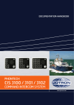
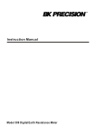
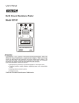
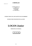
1
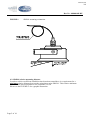
DOCUMENTATION HANDBOOK PHONTECH SR 8200 SOUND RECEPTION SYSTEM www.jotron.com Hanbook page 1/20 SOUND RECEPTION SYSTEM – SR 8200 USER MANUAL CONTENTS Document No.: N/A 08800-002-DE Description: User Manual Contents Sound Reception System (Ver. 05827) Description 97802-000-CO Sound Reception System, Commissioning Procedure 97802-003-EC Master Station, SR8200, External Wiring 08800-001-ML SR8200 Master Station, Ver. 05827, Mechanical Layout 97802-002-ML Microphone Unit, SR 8201, Mechanical Layout Ver. 2013.06 Unit Type: System System Page (pdf) 1 2-15 System 16 SR 8200 SR 8200 17 18 SR 8201 19 Hanbook page 2/20 Doc.No.: 08800-002-DE 02 2013.06.04 REVISION, CN00189 ASK ME ASK 01 0 2012.04.17. 2008.11.03. REVISION, CN00072 FINAL DOCUMENTATION ASK CD AHJ ASK PREPARED CHECKED APPROVED REV No: TITLE: ISSUE DATE REASON FOR ISSUE SOUND RECEPTION SYSTEM VERSION 05827 DESCRIPTION. This document is the property of PHONTECH and must not be copied or shown to a third person without our written acceptance. In the interest of product improvement, PHONTECH reserves the right to alter specification and design without notice. SIZE: A4 UED no: 95 DOC no: 08800-002-DE FILE NAME: 08800-002-DE Page 1 of 14 Hanbook page 3/20 Doc.No.: 08800-002-DE CONTENTS 1. INTRODUCTION Page 3 2. GENERAL DESCRIPTION Page 3 3. FACILITY LIST Page 3 4. INSTALLATION Page 4 5. INSTALLATION PROCEDURE Page 10 6. OPERATION AND FUNCTIONALITY DESCRIPTION Page 11 TECHNICAL DATA Page 13 7. Page 2 of 14 Hanbook page 4/20 Doc.No.: 08800-002-DE 1. INTRODUCTION. A sound reception system (SR8200) consists of one MASTER station, type SR8200, mounted on the bridge and 2 or 4 distributed microphones, type SR8201, located at the port and starboard, or port, starboard, fore and aft on the vessel. The SR8200 system will then serve as an acoustical electronic navigational aid to the officer on the watch to hear outside sound signals inside a totally enclosed bridge. This makes him able to alone perform look-out function as required in the International Regulations for Preventing Collision at Sea, 1972. The system will receive sound signals in all directions in the audio band 70Hz – 820Hz and reproduce these incoming signals acoustically inside the bridge. It will, in a normal 4-microphone installation, indicate the approximate direction of the signals using 4 light indicators on the front panel. The indication will be either of these combinations: Fore – starboard Fore – port Aft – starboard Aft – port The compact design makes the SR8200 system easy to install. The space requirement for the Master station SR8200 is DIN-standard 144 x 144 mm flush mounted. Wall mounting requires a backbox. The SR8201 microphone is delivered with a mounting bracket and 2m cable for easy termination. 2. GENERAL DESCRIPTION. The SR8200 system is delivered as follows: SR8200, MASTER STATION for max. 4 microphones, type SR8201. SR8201 MICROPHONE External LOUDSPEAKER (optional) Wall mounting box (optional) The MASTER station SR8200 contains all the electronics required in a sound reception system. 3. FACILITY LIST SR8200: Connection for 4 microphones SR8201 (port, starboard, fore and aft) Built-in wide-band loudspeaker. Loudspeaker volume control Back lighted position LED’s (faint green). Red direction/activity indicator LED’s. External loudspeaker output connection. Sensitivity adjustment (one potentiometer per microphone inside the unit) Mute circuit for the ships own foghorn Page 3 of 14 Hanbook page 5/20 Doc.No.: 08800-002-DE Configuration dependent squelch function Always open Active microphone channels open only All microphones open during arbitrary activity Configuration dependent electronic foghorn bypass-filter 70 Hz- 820 Hz No filter Filter: 12 dB/octave at 820 Hz Filter: 24 dB/octave at 820 Hz Configuration dependent LED indicator behaviour Sector direction display – indicating by 2 simultaneous illuminating lights the approximate direction of the sound source. Main direction display – indicating by 1 illuminated light, the main direction of the sound source. All direction lights displays individually – FOR TEST and INSTALLATION PURPOSES SR8201: Condenser microphone for very good reception in the required audio band Anti condensing element. Robust construction withstands rough environments. 4. INSTALLATION: 4.1. Mounting: The master station SR8200 is delivered for flush mounting. On request the unit may be delivered with wall-mounting box (option). Front plate dimensions SR8200: Cut- out dimensions for flush mounting: Depth, flush mounted: Depth, wall mounted: 144 x 144 mm. (H x W) 115 x 115 mm. (H x W) 100 mm. 100 mm. IMPORTANT: The SR8201 microphone unit must be mounted according to the drawing shown in figure. 1 This is important to prevent water penetration and corrosion. Special care must be taken to locate the microphone units to a silent place, with least possible wind noise and without a direct sight line from the exhaust funnel or other noise sources to the microphones vibrations from the ship. The cable must be looped in the microphone end to make service possible and to reduce the risk of vibration transmission through the cable. Page 4 of 14 Hanbook page 6/20 Doc.No.: 08800-002-DE FIGURE 1. SR8201 mounting orientation. 4.2. SR8201 relative mounting distance In order to achieve sufficient sound direction detection control there is a requirement for a minimum relative distance between the microphone units SR 8201. This relative minimum distance from each microphone to the centreline is 0.5m. Please see the FIGURE 1b for a graphic illustration. Page 5 of 14 Hanbook page 7/20 Doc.No.: 08800-002-DE FIGURE 1b. SR8201 relative mounting distance 4.3. Cable requirements: Cable between master SR8200 and microphones SR8201: Power cable: To external loudspeaker: Minimum conductor area all cable types: Two pairs individually twisted, outer screen. Single pair, twisted, outer screen. Single pair, twisted, outer screen. 0.75 sq. mm. IMPORTANT: TO SECURE UNINTERFERED OPERATION, DO NOT COMBINE SIGNAL CABLES WITH OTHER CABLE TYPES SUCH AS MAINS SUPPLY etc. THE CABLING FOR THE SOUND RECEPTION SYSTEM SHOULD BE A SEPARATE NETWORK. THE MICROPHONES MAY BE DAMAGED IN CASE THE 4 WIRES ARE EXCHANGED AND SPECIAL CARE MUST BE TAKEN TO TERMINATE ACCORDING TO THE DIAGRAM 97802-003-EC (ALSO IN THE SYSTEM HANDBOOK) Page 6 of 14 Hanbook page 8/20 Doc.No.: 08800-002-DE 4.4. Configuration: The SR8200 have some configuration settings in order to make a very flexible system. This configuration alternatives can be selected by internal jumpers and DIP switches. IMPORTANT: SPECIAL CARE MUST BE TAKEN WHEN OPERATING INTERNAL JUMPERS AND DIP SWITCHES AS THE PCB CONTAINS LIVE ELECTRONICS. PREFERABLY POWER SHOULD BE TAKEN OFF THE UNIT IN ADVANCE OF OPENING. FIGURE 2. SR8200 PCB layout / location drawing POTENTIOMETERS FOR MICROPHONE CHANNEL ADJUSTMENT DIP SWITCHES 1 2 3 4 5 6 7 8 CONFIGURATION DIP SWITCHES OFF CONFIGURATION JUMPERS MAIN POWER FUSE SR 8201 ANTI CONDENSING ELEMENT POWER FUSE Page 7 of 14 Hanbook page 9/20 Doc.No.: 08800-002-DE 4.4.1. Dip switches: INPUT FILTERING: DIP SW 2 0 0 1 1 0 0 1 1 3 0 0 0 0 1 1 1 1 1 0 1 0 1 0 1 0 1 Description No function No microphone lowpass filter/ not valid for type approval DNV 12 dB/octave low pass filter / 820 Hz No function 24 dB/octave low pass filter / 820 Hz No function No function No function LED BEHAVIOUR: DIP SW 5 4 0 0 0 1 1 X Description Sector direction display – indicating by 2 simultaneous illuminating lights the approximate direction of the sound source. This functionality requires 4 microphones (SR8201) installed (PORT, STB., FORE and AFT. Main direction display – indicating by 1 illuminated light, the main direction of the sound source. Both 2 and 4 microphones can be used in this application. All direction lights displays individually – FOR TEST and INSTALLATION PURPOSES SQUELCH / LOUDSPEAKER BEHAVIOUR: DIP SW 7 0 1 1 6 X 0 1 Description Always ON, except during MUTE (external input) Active channel ON only All microphone channels ON during arbitrary activity OTHERS: DIP SW Description 8 X No operation / prepared for future use Page 8 of 14 Hanbook page 10/20 Doc.No.: 08800-002-DE FACTORY SETTING: 8 0 7 1 FACTORY DIP SWITCH SETTING 6 5 4 3 0 0 0 1 2 0 1 0 4.4.2. Jumpers: LOUDSPEAKER OPERATION: JUMPER Description ST 1 ON Enable internal loudspeaker (alone or in addition to an external loudspeaker) OFF Disable internal loudspeaker (external loudspeaker only) LED LIGHT BRIGHTNESS: JUMPER ST 3 ST 2 OFF ON ON OFF Description The intensity is controlled by an external potentiometer connected to the PCB connector J2.6 & J2.7 Normal preset intensity FACTORY SETTING: FACTORY JUMPER SETTING ST 3 ST 2 ST 1 ON OFF ON Page 9 of 14 Hanbook page 11/20 Doc.No.: 08800-002-DE 5. INSTALLATION PROCEDURE: In order to maximise the performance of the system, each installation must be configured and adjusted on site. In most cases the configuration of DIP switches and jumpers can be kept in the factory set positions, but customer requirements may require different settings. Each microphone channel must be separately adjusted. Inside the unit there are 4 potentiometers available, one per channel. The potentiometers are of multiturn type with 15 turns from max to min. In order to adjust the microphone channels properly, the DIP switches must be set to INSTALLATION MODE: 8 0 7 0 6 0 Installation mode 5 4 1 0 3 X 2 X 1 X1 In this mode all LED’s will work independently of each other. The system must be powered up and set to work. The surrounding noise level should be as close to the real operating conditions as possible. Avoid adjustments during unnatural noise situations. 5.1. Simplified procedure: This procedure does not require additional instrumentation, and might be used in most cases. In case of problems the advanced procedure must be followed. Adjust each channel’s potentiometer counter clockwise until the corresponding LED light up. Or clockwise until it turns off and then carefully counter clockwise until it lights up again. This sets the activation threshold level equal to the surrounding noise floor. To set the final working threshold level, finally turn the potentiometer ½ turn clockwise. The adjustment procedure must be repeated for all installed microphone channels. In case there are uninstalled channels the respective potentiometers must be turned 10 times clockwise to disable. 1 Set the DIP switches back to normal (factory or customer specified) before test and finalisation. The installation and the adjustment of the system are verified by using the handheld SIGNAL HORN supplied with the system (Jotron p/n 15033). Move 100-150 meters away from the ship and activate the signal horn. Verify an audible and visual indication. If possible move around the ship to verify direction indication. The adjustment of the microphones must be done with the appropriate microphone filter selected. Page 10 of 14 Hanbook page 12/20 Doc.No.: 08800-002-DE 5.2. Advanced procedure: In severe noise conditions an ambient noise level check must be carried out. The system is designed to operate in max noise conditions of 70dBA (DNV Rules for ships Pt.6 Ch.8, Sec.6 E400). The SR 8200 is not able to detect ships whistle signals below the max noise level. Wind noise may be a problem to the adjustment/detection (ref chapter 4.1 Mounting:. Wind may contain detectable frequency components. Thus system installation and adjustment should be done during no wind conditions. Use an SPL (Sound Pressure Level) meter to measure the ambient SPL level. This must not exceed 75 dBA. Higher noise levels will make the system likely to fail adjusting. The SPL output of the handheld signal horn (chapter 5.1 Simplified procedure:) is approximately 110dBA/ 1m. In order to match the ambient noise level of each SR 8201 microphone unit, the distance between the microphone and the handheld signal horn must be calculated such that the signal is detectable. Using the SPL versus distance equation: SPL =110-(20*LOG10(A)) where: SPL : The Sound Pressure Level figure at the SR 8201 microphone unit [dBA] A : Distance between the SR 8201 microphone and the handheld signal horn [m] The maximum distance for signal detection using the handheld signal horn will then be: A=10(110-SPL)/20 Two examples: The ambient noise level is measured to be 65 dBA: The max distance between the microphone and the handheld signal horn will be: A=10(110-65)/20 = 102.25 = 178 [m] The ambient noise level is measured to be 75 dBA: The max distance between the microphone and the handheld signal horn will be: A=10(110-75)/20 = 101.75 = 56 [m] As these calculations are theoretical other factors may also come into the equation and disturb the adjustment procedure. The figures above must be considered with some care. In case the installation is done using other signal horns than the advised, it is important that the frequency is within the detection band of 70-820Hz. If the SPL output is not known an SPL/1m reading can be done to replace the 110 dBA above. A safety margin of 3-5 dBA should be added. Under the conditions above, the simplified procedure, chapter 5.1 is to be followed. Page 11 of 14 Hanbook page 13/20 Doc.No.: 08800-002-DE 6. OPERATION AND FUNCTIONALITY DESCRIPTION: The SR8200 system is operative as soon as the power is connected. Most of the functionality is configurable with DIP switches and jumpers inside the unit. It is intended these are set according to the customer’s requirements in the installation phase. They can also be set as a reconfiguration of the system, but this may require an additional re-adjustment of activation threshold limits. Other functions are installation dependent. The SR8200 contains very few operator controls and are very easy to operate. 6.1. Main system configuration (internal configuration / installation dependent): The SR8200 system can operate with 3 different microphone configurations. It will, however not comply fully with the IMO regulation MSC 70/23/Add.2 in more than the factory set configuration. COMPLIANT: [FACTORY SETTING] 4 microphones installed – port, starboard, fore and aft; Sector direction display using 2 simultaneous illuminating LED’s to indicate approximate direction. DIP switch 4 OFF / DIP switch 5 OFF NOT FULLY COMPLIANT: 4 microphones installed – port, starboard, fore and aft; Main direction / 360° display using only 1 illuminating LED. DIP switch 4 ON / DIP switch 5 OFF NOT COMPLIANT: 2 microphones installed – port, starboard Main direction / port/starboard display using only 1 illuminating LED. DIP switch 4 ON / DIP switch 5 OFF 6.2. Microphone circuit filter configuration (internal configuration): In order to customise the audio reproduction, 3 different filter configurations are available. Flat frequency response – reception close to reality. DIP switch 1 ON / DIP switch 2 OFF / DIP switch 3 OFF Medium filter response, 12 dB/ octave / 820Hz – some hollow sound letting in mostly fog horn sounds. DIP switch 1 OFF / DIP switch 2 ON / DIP switch 3 OFF Maximum filter response, 24 dB/ octave / 820Hz – hollow sound letting in only fog horn sounds. DIP switch 1 OFF / DIP switch 2 OFF / DIP switch 3 ON [FACTORY SETTING] 6.3. Squelch / loudspeaker behaviour (internal configuration): It is also possible to configure some alternatives for the behaviour of the loudspeaker (internal/external). Always on – except during mute from the ships own foghorn. DIP switch 7 OFF. Muted during no activity, all microphones are monitored during arbitrary activity. DIP switch 6 OFF / DIP switch 7 ON. Page 12 of 14 Hanbook page 14/20 Doc.No.: 08800-002-DE Muted during no activity, only the microphones on the active microphones are monitored during activity. DIP switch 6 ON / DIP switch 7 ON. [FACTORY SETTING] 6.4. Loudspeaker connection (installation dependent): The SR8200 is prepared for connection of external loudspeaker(s). Terminals are provided for this purpose with the capacity of driving an 8 Ohms loudspeaker. With an external loudspeaker connected the internal loudspeaker can be disabled. This is done during installation by removing the jumper ST1. 6.5. Master station SR8200 volume adjustment (operator control): The volume knob does the volume adjustment, clockwise from silent to maximum. Both the internal and, if connected, the external loudspeaker is affected by the volume adjustment. 6.6. LED indicators (operator control: The LED indicators are bicolour green and red. The green light is faint and serves as backlighting of the panel. The red lights are bright and indicate activity direction. The indication modes are described in the previous chapter; 6.1. Figure 3 shows LED sector versus sound source directions. FIGURE 3. LED sector indication diagram ACTIVE LIGHT INDICATOR NON-ACTIVE LIGHT INDICATOR Page 13 of 14 SECTOR: FORE / PORT SECTOR: FORE / STARBOARD SECTOR: AFT / PORT SECTOR: AFT / STARBOARD Hanbook page 15/20 Doc.No.: 08800-002-DE 6.7. System mute (installation dependant): There is provided terminals for connection of an external system mute facility. This is meant for the ships own foghorn circuit. The requirement is a dry closing contact input. A mute will have approximately 3 sec. release time after the activation. It will mute both the LED’s and the loudspeaker. 6.8. LED indicator intensity control (optional): The system is prepared for light intensity control. With an external or internal potentiometer connected internally the light intensity can be adjusted from minimum to maximum. The intensity control affects both the green backlight and the red direction indication light. The implementation of the LED intensity control also requires the jumper ST3 to be moved to ST2. 7. TECHNICAL DATA. SR8200: Operation voltage: Current drain: Main fuse: Anti condensing element fuse: 20 - 32 VDC 300mA typical / 1 A maximum continuos / 2 A short peak 1 AT 200 mA F Frequency range: Internal loudspeaker output power (max): External loudspeaker impedance Mute input: 70-5kHz / 70-820 Hz (configuration dependent) 5W >8 Dry closing contact Microphone capacity: 4 pcs. SR8201: Microphone: Type: Bias (max): Frequency bandwidth (min): Signal level (typical): Condenser microphone element 10V / 0.5 mA 20Hz - 20 kHz 5 mV Anti condensing element: Operation voltage: Power dissipation: 24 VDC 750 mW Page 14 of 14 Hanbook page 16/20 COMMISSIONING PROCEDURE Use the tables below as guide during the commissioning of the Sound Reception system. Installation (site):__________________________________ Customer/ client:__________________________________ Hull / building no:__________________________________ SCOPE OF SUPPLY Qty. Unit Type no. Serial no. Comments COMMISSIONING TESTS NO ACTION 1 Check if the handbook is delivered and available for commissioning. Check the installation according to installation instructions. Ref, doc. 97802-000-DE (Twisted pairs / screening) Installation procedure completed and adjustments successfully carried out. Test of functions and activation of Mic inputs by signal horn. 2 3 4 RESPONSE (OK/FAILED) COMMENTS DATE DUE FOR CORRECTION Date:___________________ Customer / clients authorized representative signature:_______________________________ Phontechs representative signature (if present): Adresse: Bromsveien 19, N-3183 Horten Tlf.: +47 33083500 fax: 33083501 www.phontech.no _______________________________ Page 1 of 1 V:\prosjekt\97802 Sound Reception SR8200\DOC\97802-000-CO.doc Hanbook page 17/20 Hanbook page 18/20 Handbook page 19/20 www.jotron.com