1
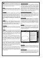
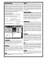
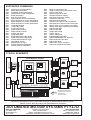
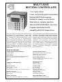
MULTI AXIS
MOTION CONTROLLER
1, 2 or 3 axis control.
Linear, circular & tangential interpolation.
Standard ISO G-Code language.
Suitable for stepper or servo motors.
Stand alone or computer operation.
Optional CAD file DXF/HPGL conversion.
Programs downloaded from PC.
Compatible with R.T.A. Stepper drives.
The S & H GOYA controllers are CNC multi axis
controllers for automatically controlling
machines using stepper or servo motors. They
are designed for synchronised motion where
two or more axes are run simultaneously.
Motion programs are written in ISO (G-Gode)
which is easy to use and is familiar to most CNC
machine operators. Programs can be written
using the ‘BACH’ PC based software which
allows operators to edit and verify programs
before downloading them to a controller via the
RS232 port.
It is not necessary to the Windows based S & H
software, it is possible to send the program files
as ASCII characters using other software
written by the machine manufacturer. Programs
can be stored in the controller and executed as
required. The controller can be used
independently of a PC as programs are stored in
a non volatile memory. Typical applications are
XYZ profiling tables, pick & place, automatic
welding, engraving, packaging machines,
glueing & painting.
SPECIFICATIONS
ENCLOSURE
DIN 144 x 144mm (panel) X 156mm aluminium
panel mounting (cut out 139 x 139mm)
WEIGHT
1kg
OPERATING TEMPERATURE
0 to 45 C
DIGITAL INPUTS
16 off, +12 to +35 VDC
opto isolated
(some required for limit+, limit- and datum inputs)
STEPPER DRIVE SIGNALS
Step, direction, drive enable, drive fault
100kHz max, 15 bit resolution
NPN current sink or 5V TTL
SERVO DRIVE SIGNALS
Velocity, direction, drive enable, drive fault
+/- 10V, 2 bit resolution
ENCODER INPUTS
5V differential
Maximum 250kHz
DIGITAL OUTPUTS
8 off, +12 to +35 VDC @ 300mA
opto isolated
CONNECTORS
(on rear panel)
Drives: D9 male
Encoders: D9 female
Inputs/Outputs: D37 female
RS232: D9 male
CAN BUS: D9 male
Analog input: D9 female
SERIAL PROTOCOL
9600 baud, 8 data bits, ODD parity, 1 stop bit
PROGRAM MEMORY SIZE
200000 characters stored in GOYA
AUTOMATED MOTION SYSTEMS PTY.LTD. - www.automotsys.com.au - [email protected]
SH-GOYA1
POWER SUPPLY REQUIREMENTS
24 VDC @ 6W
Number of Axes
The GOYA series by S & H are available with 1, 2 or 3
axes of movement. The 3rd axis, if used, must always
be a stepper motor. If more axes are needed, the S & H
‘REUBENS’ series can control upto 6 axes but it does
not have a keypad or display.
Power Supply
The GOYA requires a 24 VDC supply, although this
may be between 19 and 35 VDC. The maximum power
requirement is 6 Watts and the supply must be
smoothed.
Motors
GOYA versions are available for both stepper and
servo motors. For steppers the control output signals
are step, drive enable and direction. For servo motors
the control outputs are +/-10V velocity demand and
drive enable with encoder feedback. Both brushed and
brushless servo motors are compatible.
Outputs
The GOYA has 8 digital outputs. These are also
optocoupled, switching +24 VDC at upto 300mA. It is
permissible to use the same power supply as the
GOYA. These outputs can be switched on and off by
the motion program. They can be used to switch on
cutter tools, clamps, solenoids, punches etc.
Limits & Datums
Each axis in a machine will require limit and datum
switches for each axis (limit-, limit+ and datum). It is
usual to use normally closed switches as they are
failsafe. Upto nine of the inputs (depending on model)
are dedicated to limit and datum switches as follows:
Input 6
Input 7
Input 8
Input 9
Input 10
Datum Z axis
Datum X axis
Datum Y axis
Limit + X axis
Limit - X axis
Input 11
Input 12
Input 13
Input 14
Limit + Y axis
Limit - Y axis
Limit + Z axis
Limit - Z axis
Stepper Drives
There are two main types of stepper drive input. These
are voltage inputs and open collector current sink
inputs for step, direction and enable. The GOYA is
compatible with both types of drive, including the RTA
GMD, GMH, GAC, BCW, SAC, HDG, SDC and MIND
drives.
Emergency Stop
When an emergency stop button is hit (a normally
closed switch connected to one of the inputs) the drives
will all de-energise. The machine cannot be re started
until the GOYA is reset. Normally, an emergency stop
safety circuit will also cut off power to the drives and
other components that could cause injury.
Position Control
Stepper motors are usually run in open loop control
(without feedback). However, the GOYA can be
supplied with optional encoder inputs to close the loop
in stepper systems. Servomotors are inherently closed
loop so don’t require this option.
Interpolation
The GOYA controllers are capable of linear and circular
interpolation. Linear interpolation can be on the XY, YZ
and XZ planes. Also, linear interpolation is possible in 3
dimensional space (XYZ). Circular interpolation can
occur on either of the XY, XZ or YZ planes.
Tangential control
Apart from interpolation, the GOYA can control a knife
cutter and maintain its tangent to the path to be cut.
3D Motion
The GOYA can control motors in 3 dimensional space,
but it is not intended for full 3D sculpturing. It is possible
to machine a curve in 3 dimensional space by breaking
such a curve into small linear segments in XYZ space
and running the motors ‘point to point’, however the
programming can be tedious.
Inputs
The GOYA has 16 digital inputs. These are
optocoupled and must be switched high to +12 to +35
VDC for logic high. Normally, 24 VDC is used and this
may be the same as the 24 VDC supply for the GOYA.
These inputs can be read by a motion program. Nine of
these inputs are dedicated to limit and datum switches
for all the axes. It is also usual to dedicate one input to
an emergency stop.
Speed profiles
The GOYA has built in ramping and is capable of
trapezoidal, parabolic and ‘S’ type velocity profiles.
Time delay
Time delays (dwell) are useful in machines where
motors must wait until a machining operation is
complete. This is possible with the GOYA language
using the G04 command. Time delays from 0.01 to
9999.99 seconds are possible.
AUTOMATED MOTION SYSTEMS PTY.LTD. - www.automotsys.com.au - [email protected]
SH-GOYA2
YA
GO
Motor Speeds
Motor speed is determined by the maximum step
output frequency of 100kHz for the stepper model
GOYA and the maximum encoder input frequency of
250kHz for the servomotor or stepper & encoder
models. For example, if you are using an open loop
stepper motor drive with 4000 steps/rev resolution, the
maximum motor speed will be 100000/4000 = 25
revs/sec.
Programming Language
The motion language is ‘ISO’ of G-Code which is used on CNC machine tools. Machine operators will be familiar
with this and it won’t be necessary to use computer programmers to program the controller. The G-Code
commands are listed at the end of this brochure. Some commands will not be available in models without
interpolation. An example of a G-Code program is shown in the diagram. This could be a router, oxy cutter, laser
or plasma cutter.
PATH CODE
DESCRIPTION
1
Goto
(20,20) rapidly, speed 1000mm/min
G00
X20
Y20
F1000
(20,50)
(60,50)
3
Lower Z to 20mm at 500 mm/min
G00 Z20 F500
Y
Turn output 1 ON
G68 P1
(60,35)
7
2 G01 X20 Y50 F300
Goto (20,50), speed 300mm/min
Goto (60,50) at same speed
2
4 3 G01 X60 Y50
(60,40)
4 G02 X60 Y20 I60 J35
Clockwise arc ending (60,20), centre (60,35)
5 G01 X20 Y20
Goto point (20,20), same speed
6
Turn output 1 OFF
G67 P1
Raise Z axis to 0mm at 500 mm/min
G00 Z0 F500
5
(20,20)
(60,20)
6 G00 X60 Y40 F1000
Goto (60,40) rapidly, speed 1000 mm/min
1
8
Lower Z to 20mm
G00 Z20 F500
Turn output 1 ON
G68 P1
7 G02 X60 Y40 I60 J35 F300 Arc ending at (60,40), centre (60,35)
X
Turn output 1 OFF
G68 P1
Raise Z to 0mm at 500 mm/min
G00 Z0 F500
8 G00 X0 Y0 F1000
Goto datum 1000 at mm/min
On the fly speed change
At times it is necessary to change speed of a motor,
according to a program, while still in motion and
without stopping the motor. This can be achieved by
the G57 and G58 auto linkage commands.
P.L.C.
Often, a machine also requires a lot of logic switching
and monitoring as well as motor control. The GOYA can
be provided with a P.L.C. option, expandable up to 128
inputs and 128 outputs using CAN bus. The PLC
function which is programmed in ladder logic runs
independently from the motor control.
Protection
The GOYA has inbuilt password protection preventing
unauthorised use of a machine. Furthermore, when
controlling the GOYA from a PC, different machine
operators can be assigned different passwords
depending on competence and level of options
available.
Analog Inputs
The GOYA can be supplied with optional 6 analog
inputs, 0-5V, 10 bit and a +5V DC excitation for
potentiometers and sensors. These analog inputs can
be read by a program.
Analog Outputs
The GOYA can be supplied with 2 optional analog
outputs, +/- 10V, 12 bit. This option is only available
with the stepper versions of GOYA.
Engineering Units
All programming is done in engineering units such as
millimeters or inches and not motor revs, steps or
encoder pulses.
Precision
Theoretical positions are accurate to 6 decimal places,
however, for simplicity, the user can program the
desired number of places displayed.
Continuous Execution
Using the G57 and G58 commands, the GOYA will
perform continuous execution of segmented paths.
This is essential in cutting applications where a
stationary cutting tool will burn the workpiece.
CAM function
The GOYA can also perform a CAM function. This is to
run a motor at a particular velocity profile according to a
lookup table of speeds versus distance.
Master/slave
The GOYA can also run a motor at a programmed
speed ratio to a machine, as sensed by an encoder.
This can be used to control feed speeds at a ratio to
spindle speed for thread cutting.
Variable management
The GOYA can also perform mathematical operations
on variables (eg. obtained from analog inputs).
Operators are + - * / ^ and square root.
Housing
The GOYA is housed in a panel mounting aluminium
extruded DIN 144 x 144mm case (CAMA R2082-145).
Brackets are supplied to mount it in a panel cut out, 139
x 139mm. All connections are at the rear of the GOYA.
Although the depth of the case is 148mm, allow 217mm
for connectors at the rear.
Probe
For scanning it is necessary to have a probe input to
sense position. This is possible as the GOYA inputs are
high speed. An axis is moved at a defined speed using
the G06 command and as soon as the probe is hit, the
motor will stop and the position can be read by the
GOYA.
AUTOMATED MOTION SYSTEMS PTY.LTD. - www.automotsys.com.au - [email protected]
SH-GOYA3
Speed change
Speed is defined by the ‘F’ command in the program.
Overall speeds (all axes) can also be manually
changed while the program is still in operation by keys
on the front panel or computer screen.
Loops
If you had to machine a large number of identical items
the program would be long. It is possible to write a
program for one item and repeat it many times in an
array.
GOYABOX
The standard GOYA is supplied with a keypad and
numeric display. This enables an operator to select
programs and manually jog or datum the machine. In
applications where the GOYA will be controlled by a
computer or programs are rarely changed, a lower cost
version called the GOYABOX can be supplied. The
keypad and display are replaced by a blank aluminium
plate.
Settings
When setting up the GOYA there are numerous
settings such as motor speeds, acceleration rates,
input switch logic, scaling factors etc. Once these are
programmed and stored in the GOYA memory, an
unauthorised operator will not have access to them.
Subroutines
When run in stand alone mode, the GOYA can support
subroutines (nested to 8 levels) to make program size
smaller.
Control
The GOYA has a serial port, allowing it to be interfaced
to a PC running Windows 95 or 98. Using the S & H
BACH software, programs are written, saved, edited,
graphically verified and then sent to the GOYA. The
dongle protected BACH software is written by the
manufacturers of the GOYA.
There are two modes of operation with the GOYA. In
the first mode, the computer is controlling the machine
and motion programs are sent to the GOYA in
packages as the machine is running. This is useful for
very large programs where you want to view status on
the screen.
Downloading Software
If you do not wish to use the BACH software to
download programs, it is possible to do this yourself.
The motion program just consists of ASCII codes and
the GOYA manuals provide all the data transfer
commands to send programs through the comms port.
This is handy if you have a small number of GOYA
programs that are used repetitively and are rarely
changed. However, you will need an experienced
computer programmer for these applications.
Programming without Computer
It is possible to edit and enter motion programs into the
GOYA using the keypad and display. This does not
require a computer. However, the procedure is not
recommended for large programs as it can be very time
consuming and has a high error rate.
Manual Jogging
It is possible to manually jog axes on the machine,
either when the GOYA is linked to a computer or
running alone. When using BACH, jogging can be done
by clicking on an axis icon and pressing arrow keys for
continuous motion or moving a set distance at a time.
The machine can be datumed by clicking on a datum
icon.
BACH Lite
The GOYA is supplied with BACH Lite software at no
cost. This does not allow you to download motion
programs. It enables you to set up the GOYA to the
correct machine parameters such as scaling, speeds,
accelerations and inputs.
Iasjias
fidjjddjijd
iasiasddji
iijiosdjsdio
iodjs
Ggauia
IIJAas
PLC
Sdsad
asdsd
asdsd
jjkkjk
asd
PLC
Sdsad
asdsd
asdsd
jjkkjk
asd
942826
346421
341235
2023
Sidjisu
sadod ihiasf
asdfijdoj
sdiasioojdoas
aspida dj
siod
s&h
Aisii sdiias asijd fffsdf
asiasdaassdf fd
asdiijisasisdfsdf
asiasijdasdd
"Ellipse”
G00X297.545Y139.243 F15000
G00 Z35 F1000
G57
G03X254.908Y216.779R-117.237
G03X209.681Y239.946R-147.444
G03X153.055Y248.310R-187.084
G03X96.551Y239.161R-187.084
G03X51.650Y215.367R-147.444
G03X20.071Y177.844R-117.237
G03X10.095Y137.247R-85.184
G03X20.634Y96.792R-85.184
G03X52.731Y59.711R-117.237
G03X97.958Y36.543R-147.444
G03X154.584Y28.180R-187.084
G03X211.089Y37.329R-187.084
G03X255.989Y61.123R-147.444
G03X287.569Y98.646R-117.237
G03X297.545Y139.243R-85.184
G00 Z0 F1000
G00 X0 Y0 F15000
M02
In the second mode, motion programs are downloaded
into the GOYA and then saved in a non volatile
BACH 2000 - PROGRAM EDITING
memory. Then a program can be run by selecting the
required program from the GOYA keypad and display
and starting. The computer does not need to be BACH 2000
connected for this operation!
This is the full version of BACH and allows you to
download programs into the GOYA and operate the
The memory in the GOYA is about 150000 characters. GOYA from a computer. To use this software a dongle
A typical G-Code program line like “G01 X150.0 Y20.0 is required.
F300” consists of 21 characters so you could fit 7142
lines of code similar to this. The maximum number of Computer mouse
programs is 100.
When running GOYA from a computer, functions can
be selected using a computer mouse. However, mice
do not survive long in a harsh environment so keyboard
arrow keys, F10 and return keys can also be used.
AUTOMATED MOTION SYSTEMS PTY.LTD. - www.automotsys.com.au - [email protected]
SH-GOYA4
Wait
When machining, it is sometimes necessary for the
GOYA to wait and not move motors to the next position
until it is clear and an input is sensed. This can be done
using the G66 ‘hold input’ command.
Flexible program files
The programs saved by the BACH software are basic
ASCII text files. You don’t need special codes to read
them. You can read them and edit them on a word
processor if you want. You can use other CAM
packages to generate the program and read them with
the BACH software. You could even write a program
with the mathematics to generate the lines of code for
small linear segments (such as a 3 dimensional shape)
and save the file to a disk. The BACH software is not
particularly sensitive about formatting the lines of code
but commas and stops cannot be used.
G01 X100 Y50 Z40 F1000
OK
OK to omit spaces
G01X100Y50Z40F1000
N20 G01 X100 Y50 Z40 F1000 Line numbers OK
G01 X100 Y50 OK to omit ‘F’ command
Controller assumes same F as before
X100 Y50
OK to omit ‘G’ command
Controller assumes same G as before
g01 X 100 Y 50 Z 40 F 1000
Not acceptable
No spaces or lower case
G01,X100,Y50,Z40,F1000
Not acceptable
No commas allowed.
Iasjias
fidjjddjijd
iasiasddji
iijiosdjsdio
iodjs
Ggauia
IIJAas
PLC
Sdsad
asdsd
asdsd
jjkkjk
asd
PLC
CNC
X
Y
Z
942826
346421
341235
2023
Sdsad
asdsd
asdsd
jjkkjk
asd
Sidjisu
sadod ihiasf
asdfijdoj
sdiasioojdoas
aspida dj
siod
s&h
Aisii sdiias asijd fffsdf
asiasdaassdf fd
asdiijisasisdfsdf
asiasijdasdd
C:\BACH\backet.gio
N5
0.00
546.50
20.00
+
200%
E
mm
+
R
mm
100%
+
mm
1%
CAD files
For complex shapes consisting of curves, arcs and
lines, calculating points and typing lines of code can be
difficult. It is easier to draw them using a CAD software
package. The BACH software has an option that allows
importing DXF and HPGL files produced by CAD
software and converting them into motion programs.
Subroutines for beginning and end of a profile (eg. tool
on, tool off) can be defined and automatically inserted
into the program.
Program size reduction
It is often necessary to machine a profile that consists
of many interpolated lines and arcs. A typical example
is the sole of a shoe. Because the shape was probably
generated by CAD software, it may consist of many
small straight lines joined together. The program length
can be enormous, taking up valuable memory space in
the GOYA. The BACH software has an option of post
processing the program and replacing a long list of
linear moves with a very short list of arc moves.
Tool Radius Offset
Cutting tools remove material and therefore have a
‘kerf’ which must be allowed for when programming.
Rewriting lines of code if the paths are circles, arcs and
rectangles is easy but when paths are curves or regular
shapes on an angle this can become difficult. BACH is
available with an option (extra cost), allowing you to
change sections of program code to compensate for
tool radius offset. This uses the G40, G41 and G42
commands. When this feature is used, the program
must be run from the computer using the BACH
software and may not be stored in the controller. The
controller is not able to do the real time processing
required.
Emergency Stop
Y Datum
Z Datum
BACH 2000 - MACHINE CONTROL
Terminal Mode
When running the GOYA from a computer and when
first testing a system, it is useful to be able to send
single lines of G-Code to the GOYA. This can be
done by the terminal mode that lets you type a single
line and download it by pressing return.
Video replay
When using servomotors, tuning the drive and GOYA
can be critical. To assist in doing this, the BACH
software enables you to program a motor move and
look at the response on the computer screen, graphed
as coordinates and velocities with respect to time. The
theoretical response can be compared to actual
response. This feature is not available with stepper
motors without encoders as there is no way of knowing
actual position.
EMC
The GOYA is CE marked and complies with
electromagnetic compatibility standard 89/336/EEC
and should be installed according to the Appendix to
Teach mode
hardware manual “CNC1, Appendix to User’s manual
When using the BACH software, complex shapes can for S & H Controllers” It is the machine manufacturer’s
be programmed by manually jogging motors to point responsibility to ensure the machine conforms to
positions and clicking enter which automatically Australian EMC Framework. Our EMC statement
generates a line of code in the program. This is useful applies and is available on request.
when programming shapes that are not easily
mathematically defined and where accuracy is not Installation
We strongly recommend that a competent engineer
critical.
familiar with mechanical, electrical, electronic and
Safety
computer systems be involved with the installation and
It is the machine manufacturer’s responsibility to setup of the GOYA controller.
assess the safety risks and ensure the machine
conforms to AS4024-1
.
AUTOMATED MOTION SYSTEMS PTY.LTD. - www.automotsys.com.au - [email protected]
SH-GOYA5
X Datum
SUPPORTED COMMANDS
G00
G01
G02
G03
G04
G06
G16
G17
G18
G19
G20
G21
G22
G25
G26
G27
G30
G31
G32
G50
G51
G52
G90
G91
Rapid move (no interpolation)
Move with interpolation
Clockwise circular Interpolation
Anticlockwise circular Interpolation
Dwell (time delay)
Run axis continuously
Define plane of circular interpolation
Select XY plane for circular interpolation
Select XZ plane for circular interpolation
Select ZY plane for circular interpolation
Unconditional jump
Jump if flag TRUE
Jump if flag FALSE
Define minimum limits
Define maximum limits
Cancel work limits
Recall subroutine
Recall subroutine if flag TRUE
Recall subroutine if flag FALSE
Cancel displacement of origin
Seek Datum switch
Displacement of origin
Activate absolute coordinates
Activate relative coordinates
G53
G54
G55
G56
G57
G58
G61
G62
G63
G64
G65
G66
G67
G68
G69
G70
G71
G80
G81
G82
G83
G84
G94
Origin of axes at this point
Origin of axes at this point (software set)
Save current origin
Restore origin set by G55
Activate continuous velocity
Deactivate continuous velocity
Activate accurate stop
Deactivate accurate stop
Activate ‘don’t wait for end of movement’
Deactivate ‘don’t wait for end of movement’
Wait for input to go low before proceeding
Wait for input to go high before proceeding
Switch output OFF
Switch output ON
Assign state of flag
Units in inches
Units in millimetres
Enable/Disable cam table
Define DISENGAGE cam positions
Define automatic cam table
Define cam factor
Define cam velocity variations
Deactivate tangential tool guide
TYPICAL SCHEMATIC
Computer
X DRIVE
+5 VDC
GOYA
+5V
STEP
DIR’N
ENABLE
FAULT
0V
4
3
8
7
2
5
+5V
STEP
DIR’N
ENABLE
FAULT
0V
7 Stepper Drive
5 SDC, HGD, SAC
3
17
6
16
4
15
2
14
9
13
8
+5V
STEP
DIR’N
ENABLE
FAULT
0V
Stepper Drive
7
5 SDC, HGD, SAC
3
17
6
16
4
15
2
14
9
13
8
DRIVE
OUTPUTS +24 VDC
INPUTS
+24 VDC
300mA
max.
IN1
IN2
IN3
IN4
IN5
IN15
IN6
IN7
IN8
IN9
IN10
IN11
IN12
IN13
IN14
IN16
+24V
INPUTS/OUTPUTS
OUT 1
OUT 2
OUT 3
OUT 4
OUT 5
OUT 6
OUT 7
OUT 8
-
1
2
3
SUPPLY
+
LOAD
Power
Supply
Y DRIVE
9
8
7
5
4
3
2
1
Z DRIVE
9
8
7
5
4
3
2
1
RS232
COMS PORT
STEP, DIRECTION & ENABLE SIGNALS
24 VDC
4
3
8
7
2
5
Stepper Drive
7
5 SDC, HGD, SAC
3
17
6
16
4
15
2
14
9
13
8
GOYA Multi axis controller
4
3
8
7
2
5
X
Y
Z
Normally Closed switches for
ESTOP, Datums and Limits
Normally Open
switches for inputs
Continuous development may necessitate changes in specifications without notice.
Motors, drives, belts & pulleys and gearheads also available.
AUTOMATED MOTION SYSTEMS PTY.LTD.
MAILING ADDRESS:
P.O.BOX 1240
WANGARA DC
W.A. 6947
PHONE: (08) 9309 1896
FAX: (08) 9309 5671
EMAIL: [email protected]
INTERNET: http://www.automotsys.com.au
OFFICE ADDRESS:
UNIT2, 7 BARETTA RD.
WANGARA, PERTH
WESTERN AUSTRALIA
SH-GOYA6 A.B.N.: 94 009 232 535
INPUT 1
INPUT 2
INPUT 3
INPUT 4
INPUT 5
IN 15
DATUM-Z
DATUM-X
DATUM-Y
LIMIT+X
LIMIT-X
LIMIT+Y
LIMIT-Y
LIMIT+Z
LIMIT-Z
ESTOP
+24V
0V
OUT 1
OUT 2
OUT 3
OUT 4
OUT 5
OUT 6
OUT 7
OUT 8
1 2 3 4 5 15 6 7 8 9 1011 121314 1617 32 2021222324252627