1
Technical Questions
PCD Series Chips
The motor will turn in a CW direction, but it does not turn in a CCW direction. What are some possible
causes for this?
Check the following:
1. Is an EL signal being input?
2. Is specification of the direction appropriate?
3. Is the selection of output method (2-pulse mode or common pulse/direction signal mode)
appropriate for the driver?
When "0" is put in the preset counter, will there be any problem with the operation of the PCL?
When you specify "0" in the preset counter and write a start command, the LSI will not operate in preset
mode. However, there will not be any problem with its operation.
Can we write data to the PCD/PCL even when the reference clock is stopped?
The PCD/PCL cannot read or write data when the reference clock is stopped.
How should unused terminals be handled?
Unused terminals should be handled as follows.
1. Input-group active-low terminals (with a bar over the terminal name) should be connected to a 5V
terminal.
2. Input-group active-high terminals (without a bar over the terminal name) should be connected to a
GND terminal.
3. Output terminals should be left open
This does not apply to input terminals connected to a CPU (such as D0 to D7, RD, WR, CS, A1, and A0)
For details, see the PDF file called "How to handle unused terminals.”
When the motor is stopped by turning ON the EL signal, how do you release the EL signal?
In order to release the EL, feed the motor in the opposite direction from that used by the EL to stop. When the
signal EL is input by a pulse signal, the current output clock will stop. However, the motor can be restarted
without taking any further action.
How is it possible to start a zero return operation while the ORG signal is ON?
The PCD series does not start the zero return. (The zero return operation is delayed.) When the ORG signal is
released, they will start to return to the zero position.
LSIs with the "zero position leave" function, such as the PCL 60xx series, can be operated even if the ORG
signal is ON by using certain setting methods.
Can we supply a signal to +-EL directly from a switch or sensor?
If the signal on the line is normally open and active LOW, it can be input directly. In order to prevent
problems from electrical noise, insert an isolation router on the line.
Is there any model that can accept input from an absolute encoder (gray code)?
All of PCD/PCL series and CCL series will only accept incremental type encoder signals there is no model that
accepts absolute encoder signals.
Is it possible to use these LSIs at ambient temperatures of 100 deg? How about operation at lower
temperatures?
The LSIs cannot be operated at temperatures of 100 degrees. However, the temperature conditions vary a
little with each model. For details, see the user's manual for each model, and operate the chip within the
specified temperature range.
Why do we set bit 3 (stop an acceleration/deceleration operation in the middle)to 1 in the output
mode command?
When bit 3 in the output mode command is 0, the PCD will execute a normal ramp-up/down. If it is set to 1:
1. The PCL will halt a ramp-up/down the instant that the bit is set to 1, and it will hold the current pulse
frequency.
2. If the PCD has stopped outputting pulses, even if an FH high-speed command is written it will feed at
FL speed without a ramp-up.
To determine the acceleration/deceleration rate when the multiplication rate is set to 2x, should we
multiply the R1/R2 value by 2?
Regardless of the multiplication rate, the acceleration / deceleration rates can be calculated using the
following formulas. Enter the same R1/R2 values as are set in each register.
For linear acceleration/deceleration:
R3 = Acceleration/deceleration time x Reference clock frequency / (R2 - R1)
For S curve acceleration/deceleration:
R3 = {Acceleration/deceleration time x Reference clock frequency / (R2 - R1)} / 2
When relationship of the values in registers R1 (FL) and R2 (FH) is R1>R2, what will the operation be
like?
The PCD/PCL series changes the speed from FL to FH speed. Therefore, when R1>R2, it will "decelerate" from
FL to FH speed. If it is currently operating at FH speed, it will accelerate from FH to FL speed.
In preset operation, when the LSI reaches the ramp-down point while feeding at FH speed, it will accelerate to
FL speed. Therefore, the shape will be an inverted trapezoid.
We want to use a 30 kpps frequency. Is it possible?
It will be possible if you select the 4x mode for the multiplication rate. (Set R4 (multiplication register) to
150.) If the reference clock is 4.9152MHz, and if the maximum value of the speed register range is "8191," the
maximum output frequency in 4x mode will be:
8191 x 150 = 32764pps
By increasing the multiplication rate, it can output several hundred kpps.
Compared with the PCL series, the PCD series has a smaller limit for the following settings:
• The number of bits in the acceleration/deceleration rate register
• The number of bits in the ramp-down point setting register
Therefore, when the FH speed is high, or you want to use a long acceleration time, the PCD series may not be
able to handle the necessary numbers.
If the ORG signal is input during preset operation, what will the R0 register value be?
ORG stop during preset operation
Make bit 1 = 1 (enable ORG signal) in the control mode command and the PCL will stop operation when an
ORG signal is input, even it is operating with the preset command. After stopping, the R0 value will be the
number of residual pulses.
Page 41 in the PCD4511/4521/4541 user's manual says "R0 subtracts one count for each pulse that is
output." If the R4 multiplication register is changed, how will the R0 counter behave?
For R0 counter and R7 setting, the R4 (multiplication register) changes the multiplication rate of the
frequency, and does not affect the number of pulses. Therefore, regardless of the setting in R7, the R0 value
will count down once for each pulse that is output.
How do we calculate the number of pulses needed for acceleration/deceleration? Can we obtain the
number of pulses needed from the register values, such as the acceleration/deceleration rates?
In the PCD series, both the acceleration and deceleration rates are equal, which means that the number of
pulses used for acceleration is equal to the number of pulses used for deceleration. Calculate the value from
the register values as follows:
CLK : Reference clock frequency (Hz)
R1 : FL speed setting
FL : FL speed (frequency (pps))
R2 : FH speed setting
FH : FH speed (frequency (pps))
R3 : Acceleration/deceleration rate
Tsud : Acceleration or deceleration time
R4 : Multiplication rate setting
Psud : Number of pulses needed for Acceleration or deceleration
(1) In the case of linear acceleration/deceleration
Tsud = {(R2 - R1) x R3} / CLK
FL = (R1 x CLK) / (8192 x R4)
FH = (R2 x CLK) / (8192 x R4)
Psud = {(FL + FH) x Tsud} / 2
(2) In the case of S-curve acceleration/deceleration
Tsud = {(R2 - R1) x R3} x 2 / CLK
FL = (R1 x CLK) / (8192 x R4)
FH= (R2 x CLK) / (8192 x R4)
Psud = {(FL + FH) x Tsud} / 2
The acceleration and deceleration rates are the same in the PCD series. Can this rate be changed after
acceleration in order to use a different rate for deceleration?
It is possible to change the acceleration/deceleration rate while operating at FH speed so that you can
decelerate using a new rate. However, if you overwrite the acceleration/deceleration rate during acceleration,
the motor will not change speed (will not begin to accelerate) for a period of "1023 x reference clock cycles"
when you overwrite the rate at certain points.
Therefore, if you want to change the acceleration/deceleration rate register; it is better to do it during
constant speed operation. It is better to overwrite the rate after confirming that bits 6 and 7 of status 0 are
"00" (in a speed operation other than an acceleration/deceleration).
Is the value put in the speed register a division ratio? (The larger value, the lower speed?)
The value is divided in the circuit. However, the value put in the speed register is the numerator, not the
denominator. Therefore, when the reference clock is 4.9152 MHz, and R4 = 600 (1x mode), the speed register
value will be equal to the speed (pps).
While in preset operation, I want to decelerate and stop the motor. In this case, can I reset (= 0) the
residual pulses in R0? If so, how?
There is no command that can be used to reset R0. If residual pulses remain in R0, and you trigger a restart,
the PCD will output the residual pulses and then stop. If there are residual pulses in R0, write a new value to
R0. The old value will be overwritten and the new value will be used. Therefore, you can write R0 = 0 when
the motor decelerates and stops.
Are triangle operation, trapezoid operation, constant speed, and one-pulse feeding all permitted as
speed patterns?
The four patterns named in the question are all possible.
In the case of triangle operation in preset operation, when the feed amount (the number of pulses to output)
is small, the PCL will decelerate the motor while still accelerating from FL speed to FH speed. Then, when the
motor reaches FL speed again, it will stop the motor.
One-pulse feeding is possible by putting a 1 in the countdown counter (R0) and triggering a start.
In the register calculation files (in the Excel document) for the PCL series, there is a data calculation
formula for triangle driving. Is there a function that can be used with the PCD series to lower the FH
speed and make the apex of the triangle flat, in order to prevent triangle driving? Should users
calculate and set the FH and rampdown point (R5) themselves?
In the PCD series, when the following condition is met,
(The Preset Amount (R0)) < (Rampdown point setting) x 2,
The motor will not reach the originally set FH speed.
It starts decelerating when the following condition is met.
R0 = Rampdown point set value
Thus, the operation pattern will be triangle driving.
There is no function in the PCD series that will automatically make the apex of the triangle flat. You should
determine whether the operation will be a triangle shape or not, and then you can set the FH speed and
rampdown point (R5).
What are idling pulses, in concrete terms?
Stepper motors cannot self-start if the maximum self-start frequency is exceeded, and they may not rotate
normally. This is called being "out-of-step."
When the PCD is triggered to start an acceleration, it starts sending pulses right after the trigger. Even with
the first pulse output, the speed (calculated from output pulse frequency) may be faster than the motor's FL
speed (because the cycle is so short). This means that the stepper motor may be out-of-step, even at an FL
speed that should otherwise be possible with a self-start made from the calculated value.
So, in order to start at self-start speed, there is a way to delay the acceleration that normally occurs right after
the start command. This allows the motor to move at FL speed for a few pulses and then start accelerating.
These few pulses that allow it to move at FL speed are referred to as "idling pulses."
In order to accelerate to FH speed in the shortest possible time, the FL speed should be set near the upper
limit of self-starting speed for the motor. However, if the idling pulses are set to "0," the initial speed will
quickly rise above the set value. So, the FL speed must be set lower than the upper limit.
Another point to consider is that, when idling pulses are used, when the acceleration has started the motor
has rotational torque, which means that the acceleration speed can be set higher. In order to reduce the feed
time for a positioning control operation, it is better to use the idling pulses and a higher FL value. Then
increase the acceleration speed (use a small acceleration rate).
We want to change the acceleration/deceleration times. Can we overwrite them while
accelerating/decelerating?
If the acceleration/deceleration rates are changed during acceleration/deceleration, the PCD may not change
the speed for 1023 reference clock cycles while overwriting, with some write timing. Therefore, we
recommend changing the acceleration/deceleration rate registers during constant speed operation. It is
better to change the rates after confirming that bits 6 and 7 of Status Register 0 are "00" (NOT
accelerating/decelerating = constant speed operation).
We are using a PCD series device. After starting with an FH high-speed start, the motor does not
decelerate when the rampdown point is reached.
To decelerate using the rampdown point, start the motor with an FH high-speed start in preset operation, and
when R0 (preset counter) becomes less than R5 (rampdown point setting register), the target speed will
change to FL speed. Then the deceleration will start.
Possible explanations for why the PCD does not decelerate when the rampdown point is reached are as
follows.
1. The R5 (rampdown point set register) value is not appropriate.
Method for checking: Read the R5 register value. -> See if bit 5 (PC<=R5) in Status 0 is "1" when you
are within the rampdown point range.
2. The constant speed mode is overwritten during operation.
Method for checking: Read the start mode command using the extension monitor.
3. The FL speed is overwritten with the same value used for the FH speed.
Method for checking: Read the R1 (FL) register value.
4. Bit 3 (stop acceleration/deceleration in the middle) of the output mode is "1."
Method for checking: Read the output mode command using the extension monitor.
5. Triangle driving with S-curve acceleration/deceleration is occurring
Method for checking: Check whether the preset amount/2 is greater than R5.
The recommended reference clock for the PCD series is 4.9152 MHz. Will there be any problem with a
4 MHz or 5 MHz clock. What is the minimum frequency?
There is no minimum value. Since the PCL can use a clock up to 10 MHz, there is no problem with using a 4
MHz or 5 MHz clock. We recommend 4.9152 MHz for the following reasons: Some formulas are provided in
order to determine the values to put in various registers. In some of these formulas, you have to use the
reference clock frequency. In particular, when setting the register for the frequency multiplication rate, if you
enter 4.9152 MHz the result will be an integer (no number on the right of the decimal point). This is rather
convenient for determining the pulse frequency. When using values other than 4.9152 MHz, the output pulse
frequency will be a number with a fraction, and it may be inconvenient for calculations and other settings.
However, there won't be any problem in operating with such a number.
When the preset counter becomes 0, how will the counter value change?
Does it count 0 -> 1 -> 2... or, 0 -> FFFFFF -> FFFFFE ->...?
In continuous operation, when the preset counter reaches 0, it changes as follows:
0 -> FFFFFF -> FFFFFE ->...
When writing registers in the PCD series, aside from R0, all the registers are either 1 or 2 bytes. Do we
need to write 0s in bits 16 to 23?
No, you do not need to write any value in bits 16 to 23 for 1 or 2 byte registers.
We want to connect to a Z80 CPU(8 MHz). Is this possible?
It is possible. A block diagram for the Z80 interface is shown on page 14 of the user's manual for
PCD4511/4521/4541.
Can the PCD output the INT signal when starting to ramp-down in preset operation?
Set bit 4 (ramp-down point INT output control) in the register to "1." The PCD will output the INT signal when
starting to ramp-down. Reading bit 1 in the status 0 register lets you monitor this operation.
What can cause the PCD to output an INT signal?
The INT signal can be output when the PCD stops (stop in preset operation, by a change in the +-EL/STP/ORG
signals, or when stopped by the stop command), or when starting to ramp-down. See page 32 (Start mode
command bit 5) and page 37 (bits in the register select command) in the user's manual for
PCD4511/4521/4541.
Even though I started the PCL in the preset mode, and enabled the ORG signal with the control
command, when the ORG signal is input will the motor stop? Is the INT output in this case?
After enabling the ORG signal, if the ORG signal is input, even in preset mode, the motor will stop
immediately. Make bit 5 =1 (output INT when stopped) in the start mode command, and start the PCL. It will
output an INT signal when stopped by the ORG signal.
We are inputting an EL signal as a pulse. Can we check this input in the status register?
The status register does not control the stop sequence. It simply reads the +EL/-EL terminals.
Therefore, when only the +-EL signal is LOW, bit 0 or bit 1 in status 1 will go ON.
Is it possible to read the status information while operating a motor? If it is possible, what stage does
the status data come from?
It is possible to monitor the status information during motor operation. The read status will be the status at
the moment that the PCD takes its reading.
Can we monitor EL, SD, and ORG on a real-time basis? (Are they the status information when the CPU
reads from the sensor?)
The current status of the sensors will be reflected in the status information when read.
We are using 4-pole excitation output to drive a motor. In order to feed the pulse signals back to the
CPU, we are also using +-PO (negative logic). In a normal deceleration stop, if the motor is stopped by
a factor such as an EL signal or an immediate stop command, and if +-PO is occasionally LOW, will the
chip return +-PO to HIGH?
Regardless of the stop factor, the PCD makes sure that the last pulse is a full length pulse. Then it stops the
motor. Therefore, when checking the clock status after an error stop occurs, it might be LOW. In this case, the
chip will reset PO to HIGH.
After setting bit 0 and 1 in the control mode command to "00" (disable the ORG and SD signals), if one
of these sensors turns ON (goes LOW), do the ORG/SD signals monitored status 1 change to 1 (ON
status)?
The status always reflects the condition of the physical terminal. Even if the ORG/SD signals are disabled (0)
with the control mode command, if the terminals go LOW level, the status of these signals will be ON (1).
In preset operation, even though the preset countdown counter is set to 0 (stop), the status does not
change to "stopping." Why? What are the conditions in which this will become 0?
Basically, when stopped the status should be "stopping." Possible causes:
1. The operation status monitor is bit 3 in status 0 (A1=0, A0=0). Are you reading a different status (a
different address)?
2. Is FL or FH speed register value "0"?
0 is not allowed for the FL or FH speed. However, if FL speed = 0 (FH speed = 0 for the preset operation in an
FH constant speed start), the last pulse may not be returned to HIGH. That is, it could stay LOW. The
operation status monitor does not change to "stopping" (=0) until the last pulse becomes HIGH. To check this,
monitor the following:
• In a constant speed preset operation without acceleration/deceleration, read the status 0 condition
when stopped.
• In a preset operation using acceleration/declaration, read the condition of status 0 when the motor is
stopped.
Please let us know which "actions" and "interrupt status" occur when the following operation is
triggered during the preset operation.
The PCD handles setting of each of the mode and overwrite register values while operating as a change in the
current operation. The start mode command is not an exception. But the PCD will not accept the start
command of the next operation. If handle the start command as a change in the current operation.
In other words, after starting the motor with an FH high-speed start in preset operation, and writing a
"deceleration stop command" (a kind of start command), the motor will decelerate and stop from that point.
I do not understand how to read the status using the PCD4541. For example, the address of status 0 is
"A1 = 0 and A0 = 0." Does this mean that we are reading the contents of the command buffer?
To say it simply, you may understand that each address stores the data for writing and the data for reading
separately.
(1) Status 0
The PCL writes A1 = 0 and A0 = 0 to the command buffer. When you want to read the data, the contents of
status 0 will be output to the data bus. (See page 16 of the PCD4511/4521/4541 user's manual.)
You can find tables describing "Setting a standard monitor " and "Setting an extension monitor" on pages 18
and 43 of the user's manual. These examples concerning status 0 are based on the assumption that R0 to R7
are intentionally selected. This should help you understand how when A1 = 0 and A0 = 0, the contents of
status 0 can be read. As above when reading status 0, there is no need to select a register.
(2) Status 1, 2, 3
As shown in the table "When the extension monitor is selected" on pages 18 and 43 of these user's manuals,
these status registers cannot be read unless R7 is selected using the register select command. Select R7 to
read the following:
• A1=0, A0=1--- Status 1
• A1=1, A0=0--- Status 2
• A1=1, A0=1--- Status 3
When the "standard monitor" is selected, status 2 and 3, and R1 to R7, cannot be read. (This is done to
maintain compatibility with a single axis PCD4500.)
We want to start four axes simultaneously with the PCD4541. Normally, we select an axis and trigger a
start for this axis. But, if we write a "start hold command" to each axis, and then provide an external
signal through the STA terminal, can we start all the axes simultaneously?
Yes you can. After inputting the STA signal, each axis will have a time lag of a few clock cycles before the first
pulse is output. However, pulse output timing will be exactly the same for all the axes.
We want to self start from any position and move to the position set by preset counter (R0) = 0, stop
the motor immediately at the R0 = 0 position, and output the INT signal. In this case, if the rampdown
point (R5) = 0, will the motor stop at the R0 = 0 position and output an INT signal?
Yes. By setting bit 4 = 1 (output an INT at the rampdown point) in the register select command, if R5 >= R0,
the LSI will output the INT signal. So, when R0 = 0 the motor will stop and the LSI outputs the INT.
Further by setting bit 5 = 1 (output an INT when stopped) in the start mode command, the LSI can output
another INT signal when the motor is stopped. By checking whether bit 4 = 1 (PC = 0 monitor) in status
register 0, the LSI can make R0 = 0, stop the motor and output an INT.
We would like to run a preset constant speed operation using the PCD4521. We set the rampdown
point R0 = 0, and set it to output an INT signal at the rampdown point. However, when the R0 becomes
0 the motor stops, but the PCD does not output the INT signal at the rampdown point. (We have pulled
the INT signal terminal up.) Can we output the INT signal by setting an INT output at the rampdown
point if we set the rampdown point to R0=0 in continuous operation?
It is possible to output a rampdown point INT when the preset counter reaches 0 and the rampdown point is
set to 0. In both preset and continuous operations, set bit 4 in the register select command to 1. The PCD will
output an INT signal when the reset value = the rampdown point.
However, the PCD will output a rampdown point INT whenever the conditions are met, assuming that the
preset value rampdown point was true at the beginning, and the rampdown point INT output was enabled.
Then, the PCD will output an INT the next time the conditions are met. For example, if rampdown point = 0,
preset = 0, the rampdown point INT output is enabled in the register select command, and "continuous
operation" is started,
FFFFFFh -> FFFFFEh -> --- -> 1 -> 0
The counter will function as shown above. When it reaches 0, the PCD will output an INT signal.
With the settings you described, the PCD should output the INT signal. It may be that the setting was changed.
Please read the R5 data using the extension monitor function when the motor is stopped and see if the values
you set have been changed.
It is better to check the details using the register select command. However, when you try to read the
extension monitor, you have to write a register select command. This means that you would have to be able to
read out what you just wrote as the register select command, and unfortunately the PCD does not have a
function for reading register select commands you have already set. Therefore, please store the values you
use in memory when using an application program to write the register select command.
We put a value in the preset counter, perform an operation and stop. Then, we want to know the cause
of the stop, whether it was caused by using all the pulses or by the EL signal (or by both). Is there any
method for evaluating the cause of a stop other than by looking at the preset counter to see if it is 0?
You can see whether the preset counter is 0 by reading R0 or bit 4 in status register 0. To see whether an EL
signal was input, you can check bits 0 or 1 in status register 1.
However, the status register only reflects the instantaneous condition at the moment when the register is
read. Therefore, if the PCD was stopped by EL turning ON and EL has gone OFF again before you read the
status register, you may not be able to see why the PCD was stopped.
The same is true for reading the residual pulses (R0 = 0). However, in this case, if the residual pulse count is 0,
you may be sure that the PCL was stopped by the preset operation.
Since the SD and EL lines are pulled up internally, is there any problem with leaving them open when
they are not being used?
They may be left open. However, to enhance noise prevention, connect them directly to a 5V terminal or
through a 1 K ohm external resistor.
We write a start command while the EL signal is ON. Then, we turn OFF the EL signal. Is it normal for
the PCL to start operation at this point?
The stop circuit using the EL signal stops the start circuit by ORing "detecting the OFF to ON edge and latched
signal of the EL" with the "EL level signal." By turning ON the EL signal, the latched signal is cleared by a reset
command (08H). Therefore, after turning ON the EL signal, write a reset command, and a start command.
Then turn OFF the EL signal. The PCD will start operation. (This is basically the same for the PCL series.)
Can we use the EL, SD, and ORG terminals for general-purpose input?
The EL terminal always stops the PCD operation and cannot be used as a general-purpose input. The ORG
input can be used as a general-purpose input if bit 0 = 0 (disable ORG signal) in the control mode command.
Also, the SD input can be used as a general-purpose input if the control command bit 0 = 1 (disable the SD
signal).
After an FH high-speed start, the PCD accelerates in the positive direction. But it does not accelerate in
negative direction. It only feeds at FL speed. Why?
If this symptom always occurs, the -SD signal may be turned ON (LOW).
After the SD signal goes ON and the motor reaches FL speed, if the SD signal goes OFF will the motor
accelerate again?
If the SD signal goes OFF, the motor accelerates. (Even if the motor is decelerating it will instantly begin
accelerating if the SD signal goes OFF.)
We would like to provide protection for the circuits in order to prevent damage to the PCD chips,
driving ICs, and motors against abnormal use by users who use the PCD chip in built-in units.
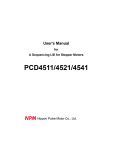
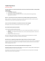
What equivalent excitation sequence signal output circuits for the PCD series are available?
The equivalent circuit for one phase is as shown in the figure on the left. The equivalent circuit is the same for
all models of the PCD series.
Using the PCD series, is there any method to decelerate and stop using the STP signal or the ORG
signal, and not make an immediate stop?
The PCD only decelerates and does not stop when using the STP and ORG signals. The SD signal only
decelerates, and does not stop the motor. Therefore, there is no other way to decelerate and stop than to use
these commands with the PCD series. (The PCL60xx/61xx series can decelerate and stop using the STP
signal.)
In the PCD4511/4521/4541 manual, an example of how to use the SD signal input is described. What
if we do not use the SD signal input?
If the SD signal is not input in the high speed zero return operation, the motor will stop immediately at the FH
speed when the ORG goes ON. (The motor may overrun a little due to inertia.) After the SD is ON, if it turns
OFF again before the ORG goes ON, the motor will accelerate again to FH speed.
If we try to perform a zero return with a constant speed, what will the operation be like?
If the motor executes a zero return with an FL constant speed start command, the motor may not change
operation regardless of whether the SD signal turns ON. (When operating at FL speed, the motor stops when
the ORG signal goes ON.)
When the motor is executing a zero return from an FH constant speed command, the motor will decelerate
from FH speed to FL speed when the SD signal turns ON, and stop when the ORG signal turns ON. If the SD
signal is not input, the motor stops immediately when the ORG signal turns ON while at FH speed. It may
overrun a little, as described in item (1) above.
(Turning ON the SD signal means "change speed from FH to FL using the current acceleration/deceleration
rates." If FH < FL, the motor will accelerate to the FL speed when the SD signal is turned ON.)
The SD signal can be monitored on the ST terminal monitor bit in the Status 1 register. If you do not use the
SD signal, this terminal status can be checked in the status register, so the ST terminal can be used as general
purpose input terminal. However, D1 in the control mode must be set to 0 (disabled).
On the PCD4541, we will use only three axes. Should the terminals for the 4th axis be left open or
should they be pulled up to VDD? If there are some terminals that can be left open, and if we leave
them open, how much power would be saved?
These terminals have an internal pull up resistor for protection. However the resistance varies between 25
and 500 k-ohms. Even if they are left open, the voltage level will probably be stable. However, to provide
noise immunity, we recommend pulling them up to VDD or shorting them together.
(Terminals in question: STA, STP, ORG, +EL, -EL, +SD, -SD, U/B, F/H)
There is no difference in the power consumption between leaving the input terminals open, pulling them up
to VDD, or shorting them. When you pull them down to GND, the current consumption will increase by 0.09
mA, to 1.8 mA per terminal.
We are currently designing a circuit using the PCD4511. This IC has only a 2-pulse output mode.
The driver we will use is a single pulse type. Therefore, we will OR the 2-pulses from the IC and use
the OTS output as a direction switching output. Is there any problem with this method?
Please be careful about doing this. +EL/-EL, +SD/-SD are available for use as machine sensor inputs. Among
these, only the signals to the PCD4511 for the correct direction are effective. For example, when the PCD is
operating in a negative direction, if the positive direction signal is output with the OTS signal, the PCD will
operate in a positive direction. In this case +SD/+ED signals become invalid and this can be dangerous.
Specifically, you must match the PCD operation direction to the OTS control.
On page 40 in the PCD4511/4521/4541 manual, there is a description of how to mask the excitation
output. In this description there is a sentence "can be used to turn off the excitation for a unipolar
drive." How about bipolar signals? If f1 to f4 are LOW, is the excitation turned off for bipolar signals?
From the sequence table on page 21, when 2-2 phase excitation is used, column 3 shows all the phases
LOW. Is this condition related to turning off the excitation output?
The current flow direction changes according to the levels of f1/ f2. In addition, when f3/f4 are HIGH, the
current will not flow. Although it would be convenient if only by selecting the bipolar mode, f3/phase4 would
become HIGH when setting the mask, the PCL was not designed this way. Therefore, even if f1 to f4 are LOW,
the excitation signals will not turn off.
When using only +-PO output terminals, should we mask the excitation signal output (set output
mode command bit 2 = 1)? Or, should we set them as outputs and leave them open as unused
terminals?
If you do not use the excitation sequence, you may mask the signals or not, as you like. However, these are
output terminals so they must be left open, regardless of whether or not you mask the signals. As the voltage
only varies on the terminal, it is not possible to be the cause of noise.
All of the PCD series models (except for the PCD4541) have a two-pulse output system for +PO/-PO.
We would like to connect a one-pulse type driver to a PCD series model that is not the PCD4541.
It seems that we need to add a gate circuit to convert the two-pulse signals to one-pulse signals. But,
we are considering always outputting a positive direction pulse through +PO terminal and providing
an external direction signal in order to change direction. In this case, what kinds of problem might
occur?
You might have the following problems:
1. Even if you attempt to drive the motor in the negative direction, the PCD believes it is driving in the
positive direction. Therefore, the "-SD signal" and "-EL" signal are disabled.
2. When you read the control mode command, the motor is always treated as moving in a positive
direction.
One method to do this is to connect an external circuit that ORs the +-PO outputs to create a pulse output, and
then use the OTS terminal for a direction signal. Using an OR circuit with only one element makes the circuit
simple. In addition, since the operation direction bit and the OTS bit are next to each other, you can make a
circuit that changes both bits at the same time, so that the problems of the SD and EL terminals will be
eliminated.
We want to perform repeat feed operations using the same start position, but the end position is
different for each feed. (A sensor turns ON to indicate the end point position.) Please tell us how to set
up the PCD.
1.
2.
3.
4.
5.
6.
7.
Set bit 3 (preset counter operation control) in the Register Select command to 0 (count output
pulses).
Set bit 2 (preset operation control) in the Control Mode Selection register to 0 (continuous
operation), and set bit 3 to 0 (positive direction)
Start the PCD by writing a Start Mode command. In order to stop the motor immediately when the
sensor turns ON, it is better to operate without using acceleration/deceleration. (We recommend an
FL constant speed start.)
When the sensor turns ON and the motor stops, the PCD reads the R0 (preset amount register) value
and obtains the number of pulses that have been output from the start point.
Set bit 2 in the Control Mode Selection register to 1 (preset operation), and set bit 3 to 1 (negative
direction).
Put the value read back into R0 and start the motor using any of the start commands.
Repeat the procedure above to program your desired operation.
We want to use the PCD45xx as a simple oscillator whose frequency can be changed easily. We don't
want to use the ramp down point. In this application, is the maximum output frequency 400 kpps?
We specify a maximum frequency of 400 kpps in the general specifications for the PCD series, taking into
account the number of bits in the registers used for the ramp down point setting and the
acceleration/deceleration rate setting. However, if you will simply be using it as an oscillator, you may use a
higher frequency.
Using the PCD series, I want to place a number of pulses in R0 at position "a" using the preset mode,
and start the motor. While operating, I want to write the preset amount "b" at position "B", then write
amount "c" at position "C." As above, we want to change preset amount during operation, and finally, I
want to stop at position "d" (positioning). Can I do this?
For a PCD:
1. Set the register select command bit 3 to 1 and temporarily stop the preset counter.
2. Change the R0 value.
3. Return the register select command bit 3 to 0.
However, these steps have disadvantages. As the PCD series was developed to put a priority on low cost, they
did not consider changing the target position while operating. Even using the steps above, the total number of
pulses may deviate (could become larger) due to CPU processing time. If the CPU processing speed is high,
perform these steps soon after status 3 bit 7 changes from 1 to 0, so that the position won't deviate. (The
result may vary with the frequency and the CPU processing speed.)
For the PCL60xx/61xx series:
These models have a "position override" function. Using this function, the target position can be changed to a
longer distance than the current position or to a position that has already been passed. For details, see the
user's manual.
In preset operation, I want to change speeds while operating. To change the speed, an operator shifts
a joystick manually (6 stages), so there are no fixed points for changing speed. If the operator shifts
the joystick while the motor is decelerating from a ramp down point, the motor should not change
speed and should be forced to decelerate to FL speed and stop at the preset amount. Are these settings
possible?
Try the following procedures and conditions:
1. Select an FL speed and five FH speeds.
2. Specify separate ramp down points for each of these five speeds.
3. The acceleration/deceleration rate must be constant during operation. (If operated at constant
speed, changes in the acceleration/deceleration rate are possible. However, there will be a large
number of ramp down points.)
4. Write the program so that, when the joystick lever is not shifted, the motor will operate at FL speed.
5. Determine with which speed the motor will operate at for each joystick position. Then, make a
program that allows writing any of the five FH speeds into the FH speed register.
When the motor is decelerated to a "new FH speed" that is a lower value than the current FH speed, and if the
FH speed is changed again, the motor will accelerate or decelerate to this new FH speed. However, if the FH
speed is changed after the motor starts deceleration from a ramp down point, it will not change back to the
new FH speed. Instead, it will decelerate to the FL speed and stop.
The conditions needed to decelerate to the FL speed from the FH speed in preset operation are:
Preset counter (= residual pulses) <= Ramp down point setting
As long as this condition is established, the motor will move toward the FL speed. If the FL speed is changed
to a higher speed, the motor will accelerate to the new FL speed and stop.
If the ramp down point setting is changed to "0," the conditions above will not be established and the motor
will accelerate to the new FL speed.
In any case, the motor will stop when the preset counter (R0) goes to 0.
We are using the PCD series. If we change the preset amount (R0) during a preset operation, does the
PCD generate any positional deviation?
We recommend the following measures:
1. Set bit 3 in the register select command to "1."
2. Change the R0 amount.
3. Return bit 3 in the register select command to "0."
Restrictions:
Due to the CPU processing time, the total number of pulses may deviate somewhat (there may be some excess
pulses). If the CPU you are using is faster, and if the R0 is changed just after output pulse level changes from
LOW to HIGH, the no positional error will occur. (It depends on the actual frequency and the CPU processing
speed). To check the state of the level, watch for a change in the lowest bit (101010....) of the countdown
counter using a CPU.
Using the PCD series, is there any method for confirming the end of acceleration? We use a sequence
to start measurements when the motor enters constant speed operation after acceleration. We
imagine that the end of the acceleration can be identified by the number of output pulses and the
measuring times.
The PCD series has no direct way to tell other than by polling to check the acceleration/deceleration status.
The interrupt process and the polling process can be used to check the status of the PCL.
With the PCL, if you use an interrupt process you have to set the PCL to generate an interrupt when the
acceleration stops. The CPU executes other operations until the interrupt is received. When an interrupt is
received, the CPU will look at the PCL status. In the interrupt process, the CPU processes the interrupt only
when an interrupt is received, and the burden on the CPU is quite small. However, the program can be rather
complicated.
On the other hand, in the polling process the CPU reads the PCL status at certain intervals and monitors when
it has stopped accelerating. If you want to monitor the PCL on a real time basis, this interval between checks
must be quite short. With the polling process, the CPU monitors the status frequently, which places a heavy
burden on the CPU. This program is rather simple.
We want to change the acceleration and deceleration time. Can we do this during acceleration?
If the motor is rotating at FH constant speed, there is no problem with overwriting the
acceleration/deceleration rate. However, if the acceleration/deceleration rates are overwritten while actually
accelerating/decelerating, it is possible the speed will not change for 1023 reference clock cycles (it will not
accelerate during this interval).
We want to overwrite the R0 register during preset mode operation. During operation in the preset
mode, if we write new data to R0 before the preset number of pulses has been output (before
stopping). How will the PCL behave? Does the PCL continue the preset mode operation with the new
R0 value until the number of residual pulses becomes 0? Or, is overwriting R0 not allowed until the
current operation is complete? Or, will it have another effect?
The PCL will continue the preset mode operation until the number of pulses according to the new R0 value
reaches zero. However, when overwriting R0, the PCL keeps outputting pulses, so that it is not possible to aim
for a precise target position.
During an operation in continuous mode, if we overwrite the R2 value and write a high-speed
command that is in the opposite direction from the current operation. How will the PCL behave? If we
write a high-speed start command for the same direction as the current operation, the PCL changes to
the new speed with acceleration. So, what happens when the start command is for the opposite
direction? Does the PCL pass through the 0 speed level and execute a linear or S-curve acceleration in
the opposite direction? Or, is the absolute value of the set speed applied and the PCL accelerates as
usual? Or does something else happen?
The R2 value is the speed figure. Therefore, to change the direction of operation, you have to set bit 3 in the
control mode command. When this bit is toggled, if the PCL is outputting pulses from the +PO terminal,
starting from the next pulse it will output pulses from the -PO terminal. Therefore, if this bit is changed during
operation, the motor will rotate in the opposite direction without any acceleration/deceleration. If you want
to output pulses in the opposite direction using acceleration/deceleration, you should decelerate and stop.
Then change this bit and start at high-speed.
In preset operation with acceleration/deceleration, we set the feed amount, initial speed, high speed,
and acceleration/deceleration times for each register. Why do we have to set the ramp down point
separately in order to decelerate and stop?
The PCD series and PCL61xx series control the operation by the number of pulses, not by the time and speed.
Therefore, they need to be told "start the deceleration when there are a specific number of residual pulses."
That is the "ramp down point." Without this setting, and since the initial value is "0," the pulses will stop
when the preset counter counts down from the FH speed and reaches 0.
All of the PCL series have an "automatic ramp down point setting function." There are two concepts used for
carrying out this function in the different models. The internal processing method for the two concepts is
different. However, the models listed above apply the concept of counting the number of pulses used for
acceleration and using this value in the ramp down point register, so that you do not need to set the ramp
down point as a separate operation.
The PCD series puts a priority on lowering the cost and the automatic ramp down point function has been
omitted. Therefore, you need to set the ramp down point yourself.
We want to use 6 PCD chips on one board sharing the same oscillator, in order to reduce the number
of reference clock oscillators. Please let us know about any precautions and the items to check for in
this case.
Refer to "DC characteristics" in the electrical characteristics on page 50 in the PCD4511/4521/4541 user's
manual. If the three items (input signal capacity, low level input current, and high level input current) are
satisfied, you may share the use of an oscillator. This applies to all the chips in the PCD/PCL series.
Are there any requirements for the rise and fall time of the reference clock?
There are no special requirements. The CLK input is a Schmitt trigger input (H: 3 V, L: 1.7 V). A little
smoothing of the rising/falling edges can change the internal shape. Do not use a clock with a pulse width less
than 50 ns.
When inserting and removing the power supply connector while the power is on may damage the LSI.
What are the possible causes and symptoms?
Precautions you should take before inserting or removing power supply connector:
1. Should not exceed the absolute maximum rating, even for a short time. When the absolute maximum
rating is exceeded, the possible symptoms may vary with the level of the excess voltage. When the
voltage on the power terminals significantly exceeds the rating, the semiconductor insulation layer
may be damaged and the element itself may be damaged as well. If the overvoltage level is small, the
LSI may malfunction or some of the I/O elements might fail or latch up. Also, if the specified input
voltage is greatly exceeded, the semiconductor insulation layer may be damaged. If the overvoltage
level is small, some of the I/O elements might fail or latch up. If the input current exceeds the
continuous rating, the I/O elements may be destroyed by heat. At some storage temperatures, the
plastic case and elements may deteriorate.
2. The I/O terminal voltage should never be above VDD and it should never be below GND. Also,
consider the power input timing. If the I/O terminal voltage level exceeds VDD or drops below GND,
it will be the same as for overvoltage in item 1) above, the I/O elements may be damaged by latching
up.
3. Be careful not to allow abnormal electrical noise to be applied to the LSI terminals. When abnormal
electrical noise is imposed on the LSI, the symptoms will depend upon the energy level of the noise.
Lower levels of noise may only cause a malfunction. Higher levels of noise may damage the elements.
4. Secure any unused input terminals to VDD or GND. If the unused terminals are not held at VDD or
GND, since most of the terminals are pulled up or down internally, significant problems may not
occur. However, their ability to resist damage from electrical noise may drop significantly if they are
left open.
5. The output terminals should never be shorted.
6. Protect the LSI from inductance produced by high voltage circuits and static electricity.
7. Use a design that protects the LSI against overvoltage due to noise, power surges, or static electricity.
Although the PCD4541 has a sequence circuit to drive a stepper motor, we will not be using it.
We would like to supply normal pulse trains to a driver, using a pulse generator to drive a motor. "Bidirectional pulses and common pulse output" are shown as the pulse types available. What are these?
Are there any restrictions?
You can select the pulse output type (bi-directional/common) to match the motor driver you are using.
You will determine the rotation direction of the motor using bit D3 (operation direction control) in the
control mode command.
Bi-directional pulse output:
The +PO terminal outputs CW pulses for rotating in the positive direction. The -PO terminal outputs CCW
pulses for rotating in the negative direction.
Common pulse output (also referred to as a "one pulse output"):
For rotating in either direction, the +PO terminal outputs the drive pulses and the -PO terminal outputs a
HIGH or LOW to signal the direction of rotation.
=> When bit D0 (+-PO output logic setting) is "0" (negative logic), if the -PO signal is HIGH, the motor will
rotate in the positive direction and when it is LOW it will rotate in the negative direction.
With the PCD4541, you can select between bi-directional pulses and common pulses using register R7. The
PCD4511 and PCD4521 do not have this choice, and only bi-directional pulse output is available. If you want
to use common pulses with these models, you will have to add a gate circuit (one IC will be enough). The PCL
series has this choice for all of the models in that series.
The type of input pulse required by a motor driver varies with each manufacturer. Looking at the
commercially available drivers, board types and box types, most are the bi-directional pulse type and the
drive ICs are mostly the command pulse type. Some board type and box type drivers have a function for
selecting a pulse output type with a dip switch.
Do we need to match the reference clock CLK with the clock frequency for the CPU that is accessing
the PCD?
No, there is no need to match frequency of the PCD to the CPU.