1
Department of Computer Science and Engineering
The University of Texas at Arlington
Team: Overdrive
Detailed Design Specification
Project: Auto Performance Analyzer
Team Members:
Gary Johns
Raul Hurtado
Brendon Harris
Zang Pham
Last Updated: Friday, October 04, 2013
11:40:58 PM
Table of Contents
Table of Contents ........................................................................................................................................ ii
Document Revision History ...................................................................................................................... vi
List of Figures ........................................................................................................................................... vii
List of Tables ........................................................................................................................................... viii
1.
Introduction..........................................................................................................................................1
1.1
Product Overview .........................................................................................................................1
1.2
Purpose and Use ............................................................................................................................1
1.3
Project Scope.................................................................................................................................2
2. Architecture Overview............................................................................................................................3
2.1
Architectural Vision ......................................................................................................................3
2.1
GUI Layer Definition ....................................................................................................................4
2.2
Processing Layer Definition..........................................................................................................5
2.3
Event Manager Layer Definition ..................................................................................................5
2.4
Database Management System Layer Definition..........................................................................5
2.5
Bluetooth Layer Definition ...........................................................................................................6
3. GUI Layer - User Input...........................................................................................................................7
3.1
Button Listener ..............................................................................................................................7
3.2
Package (User Input) .....................................................................................................................8
4. GUI Layer – I/O Controller ..................................................................................................................10
4.1
Route (I/O Controller) .................................................................................................................10
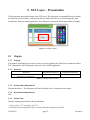
5. GUI Layer – Presentation .....................................................................................................................12
5.1
6.
Display ........................................................................................................................................12
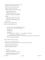
Event Manager Layer – GUI Event Handler .....................................................................................15
6.1
Route (GUI Event Handler) ........................................................................................................15
10/04/2013
page ii
Overdrive
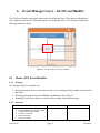
Event Manager Layer – DBMS Event Handler .................................................................................17
7.
7.1
Package (DBMS Event Handler) ................................................................................................17
7.2
Get Runs/Store/E-mail ................................................................................................................18
7.3
Get DTC List ...............................................................................................................................19
Processing Layer – Data Conversion .................................................................................................21
8.
8.1
9.
Conversion ..................................................................................................................................21
Bluetooth Layer - Data Acquisition Subsystem ................................................................................23
9.1
Run/Fetch ....................................................................................................................................23
9.2
Write/Return................................................................................................................................24
Bluetooth Layer – Sync/Pair ...........................................................................................................26
10.
10.1
Cancel ......................................................................................................................................26
11. Database Management System – DB Controller ................................................................................28
11.1
Query History ..........................................................................................................................28
11.2
Query Error Codes...................................................................................................................29
12. Inter-Components Data Flow .............................................................................................................31
12.1
Overview .................................................................................................................................31
12.2
Data Flow Definitions .............................................................................................................31
12.3
Producer-Consumer Relationship............................................................................................32
13. Quality Assurance ...............................................................................................................................33
13.1
Test Plans and Procedures .......................................................................................................33
13.2 Module/Unit Testing ....................................................................................................................33
13.2.1 GUI Layer ...................................................................................................................................33
13.2.2 Event Manager Layer .................................................................................................................34
13.2.3 Processing Layer .........................................................................................................................34
13.2.5 DBMS Layer ...............................................................................................................................35
13.3
10/04/2013
Integration Testing Approach ..................................................................................................35
page iii
Overdrive
13.3.1 GUI Layer Testing ......................................................................................................................35
13.3.2 Event Manager Layer .................................................................................................................35
13.3.3 Processing Layer Testing ............................................................................................................36
13.3.5 DBMS Layer ...............................................................................................................................36
13.4
System Verification Testing ....................................................................................................36
13.4.1 GUI Layer Testing ......................................................................................................................36
13.4.2 Event Manager Layer .................................................................................................................36
13.4.3 Processing Layer Testing ............................................................................................................37
13.4.5 DBMS Layer ...............................................................................................................................37
13.5
Test Cases ................................................................................................................................37
14. Requirements Mapping .......................................................................................................................39
14.1
Purpose ....................................................................................................................................39
14.2
Layer Requirements Traceability ............................................................................................39
14.3 Module Requirements Traceability .............................................................................................40
15. Acceptance Plan..................................................................................................................................41
15.1
Overview .................................................................................................................................41
15.2
Packaging and Installation.......................................................................................................41
15.2.1
User Manual ............................................................................................................................41
15.2.2
OBDLink MX Bluetooth Scan Tool .......................................................................................41
15.2.3
Android Application Store Submission ...................................................................................41
15.2.4
OBDLink MX Bluetooth Scan Tool Installation .................................................................41
15.3
Acceptance Testing .................................................................................................................42
15.4
Acceptance Criteria .................................................................................................................42
15.4.1 GUI Layer ...............................................................................................................................42
15.4.2 Event Manager Layer .............................................................................................................42
15.4.3 Processing Layer .....................................................................................................................43
10/04/2013
page iv
Overdrive
15.4.4 DBMS Layer ...........................................................................................................................43
15.4.5 Bluetooth Layer ......................................................................................................................43
16. Hardware Components ........................................................................................................................44
16.1 Overview........................................................................................................................................44
16.2 OBDLink MX Bluetooth Scan Tool ..............................................................................................44
16.2.1 Purpose ...................................................................................................................................44
16.2.2 Specifications ..........................................................................................................................44
16.2.3 Interfaces.................................................................................................................................44
16.3 Android Device with Bluetooth Capability ...................................................................................45
16.3.1 Purpose ...................................................................................................................................45
16.3.2 Specifications ..........................................................................................................................45
16.3.3 Interfaces.................................................................................................................................45
16.4 ECUsim 2000 OBD-II ECU Simulator .........................................................................................46
16.4.1 Purpose ...................................................................................................................................46
16.4.2 Specifications ..........................................................................................................................46
16.4.3 Interfaces.................................................................................................................................46
Appendix A: Acronym/Glossary ...............................................................................................................48
Appendix B: Pseudo-Codes .......................................................................................................................51
Appendix C: Generic Diagnostic Trouble Codes ......................................................................................55
10/04/2013
page v
Overdrive
Document Revision History
Revision Revision
Number Date
01.0
02.0
9/22/2013
10/04/2013
10/04/2013
Description
Rationale
Rough Draft
Baseline
review corrections and updates
page vi
Overdrive
List of Figures
Figure 2 - 1 Architectural diagram of system ..............................................................................................3
Figure 2 - 2 Detailed Design diagram of system .........................................................................................4
Figure 3 - 1 Button Listener module............................................................................................................7
Figure 3 - 2 Package module (User Input)...................................................................................................8
Figure 4 – 1 Route module (I/O Controller) ..............................................................................................10
Figure 5 – 1 Display module .....................................................................................................................12
Figure 6 – 1 Route module (GUI Event Handler) .....................................................................................15
Figure 7 – 1 Package Module (DBMS Event Handler) .............................................................................17
Figure 7 – 2 Get Runs/Store/E-Mail module .............................................................................................18
Figure 7 - 3 Get DTC List module.............................................................................................................19
Figure 8 – 1 Conversion module ...............................................................................................................21
Figure 9 - 1 Run/Fetch module ..................................................................................................................23
Figure 9 - 2 Write/Return module .............................................................................................................24
Figure 10 – 1 Cancel module .....................................................................................................................26
Figure 11 – 1 Query History module .........................................................................................................28
Figure 11 - 2 Query Error Code module ....................................................................................................29
Figure 12 - 1 Producer-Consumer Relationship mapping of Components................................................32
10/04/2013
page vii
Overdrive
List of Tables
Table 3 - 1 Button Listener module interfaces ............................................................................................7
Table 3 – 2 Package (User Input) module interfaces ...................................................................................9
Table 4 – 1 Route (I/O Controller) module interfaces ...............................................................................10
Table 5 – 1 Display module interfaces ......................................................................................................12
Table 6 – 1 Route (GUI Event Handler) module interfaces ......................................................................16
Table 7 – 1 Package (DBMS Event Handler) module interfaces ..............................................................17
Table 7 – 2 Get Runs/Store/E-Mail module interfaces ..............................................................................18
Table 7 - 3 Get DTC List module interfaces .............................................................................................19
Table 8 – 1 Conversion module interfaces ................................................................................................21
Table 9 - 1 Run/Fetch module interfaces ...................................................................................................23
Table 9 - 2 Write/Return module interfaces ..............................................................................................24
Table 10 – 1 Cancel module interfaces......................................................................................................26
Table 11 – 1 Query History module interfaces ..........................................................................................28
Table 11 - 2 Query Error Codes module interfaces ...................................................................................29
Table 12 - 1 Module Component Data Flow Definitions ..........................................................................32
Table 13 – 1 Test Cases .............................................................................................................................38
Table 14 - 1 Layer Requirements Traceability matrix...............................................................................39
Table 14 - 2 Module Requirements Traceability matrix ...........................................................................40
Table 16 - 1 Operating Specifications for OBDLink MX Bluetooth Scan Tool .......................................44
Table 16 - 2 Specifications for ECUsim 2000 OBD-II ECU Simulator....................................................46
Table C - 1 Table of generic Diagnostics Trouble Codes .........................................................................67
10/04/2013
page viii
Overdrive
1. Introduction
1.1
Product Overview
The Auto Performance Analyzer shall consist of one mobile application, running on a smartphone or
tablet, for a pre-existing COTS (Commercial Off The Shelf) device that will plug into any car’s (model
1996 or newer) On Board Diagnostics – generation II connector ( OBD-II). The pre-existing module
shall connect and communicate with the mobile application, only returning data that was requested, via
Bluetooth. The COTS device is commercially designed to be small and can handle temperature extremes
of -20°C to +75°C.
The mobile application shall query the on-board computer through the COTS device, which will obtain
the data from the car and will provide such data to the mobile application. This application will give the
user the option to choose the parameters of interest from a list and will display the data in real time.
The mobile application shall provide the user with the option to retrieve and clear trouble codes that are
produced by the car when the check-engine light is on. The mobile application will retrieve the trouble
codes data from the car and pull the information from a trouble code database stored in the device when
the application is installed. The trouble code retrieval, interpretation and clear feature will be displayed
in a separate screen independent of the parameter’s display screen.
1.2
Purpose and Use
The purpose of this document, Detailed Design Specification or DDS, is to extend the Architecture
Design Specification Document (ADS) and presented in detail how the Auto Performance Analyzer will
be implemented. The DDS takes the layers and subsystems from the ADS and breaks them down even
more into individual modules inside the subsystems. Included is a graphical display of the systems
architecture along with a layer by layer detailed description. Each of these modules will handle specific
tasks and will describe how modules handle those tasks and interface with other modules. The DDS will
also describe internal data, dependencies, and Pseudo Code that goes along with these modules. The
DDS document provides the Auto Performance Analyzers operating system dependencies with the
Android operating system along with the many testing considerations that must be implemented. The
DDS will lead to software implementation.
10/04/2013
page 1
Overdrive
1.3
Project Scope
The scope of the Auto Performance Analyzer project is to create a diagnostics module that interfaces
with the OBD-II connector system in automobiles to retrieve information from that automobile. The
Auto Performance Analyzer will provide a mobile user interface with enhanced tools for data logging,
vehicle diagnosis, and real time statistics. The interface will be available for Android devices, such as
smart phones and tablets. The application will be able to display the cars’ parameters data as digital
numeric readouts and graphs to the user.
In order to populate the user interface with data, the module retrieves this data from the existing OBD-II
connector, parses and reformats it. The module will then transmit it over the Bluetooth connection, to
the mobile device, in real time.
10/04/2013
page 2
Overdrive
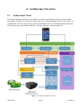
2. Architecture Overview
2.1
Architectural Vision
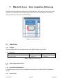
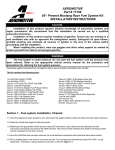
The Auto Performance Analyzer was created in a way that would allow the system to be structurally
independent. The goal was to make the software have low coupling and high cohesion. The system was
separated into five layers: the GUI layer, the Event Management layer, the Database Management layer,
the Processing layer, and the Bluetooth layer. The layer structure is shown in figure 2.1.
Figure 2 - 1 Architectural diagram of system
10/04/2013
page 3
Overdrive
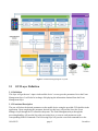
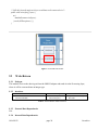
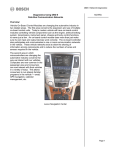
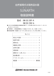
Figure 2 - 2 Detailed Design diagram of system
2.1
GUI Layer Definition
2.1.1 Definition
This layer will get the user’s input via the mobile device’s screen; pass the parameters list to the Event
Management layer. It will also be in charge of displaying the information obtained from the Event
Management layer.
2.1.2 Functional Description
The user will select the desired parameters on the mobile device using the provided GUI checklist in the
application. Upon completing the parameter desired list, this layer will pass the list to the Event
Manager Layer through the I/O controller subsystem. The Event Management layer through the
processing handler; will pass the list to the processing layer, to convert such parameters to the
corresponding OBD-II commands. The Processing layer will pass the converted command list to the
10/04/2013
page 4
Overdrive
Bluetooth OBD-II adapter connected to the car’s OBD-II port. When the car replies with the actual
parameter’s information, the Bluetooth layer will send the cars’ data back to the Processing layer to be
processed. This layer will receive the information from the Event Management layer adapter via the I/O
controller subsystem, which then it will passed to the presentation subsystem that will display the info
on the mobile device’s screen.
2.2
Processing Layer Definition
2.2.1 Definition
The Processing layer will receive the parameters list from the Event Management layer or actual
parameter data from the Bluetooth Layer and code/decode the information, and will perform processing
and the formatting into decimal form.
2.2.2 Functional Description
Upon receiving the parameters list from the Event Manger layer through the processing handler, the
Processing layer will convert this list into a stream of commands that the car’s On-board computer can
understand, and will pass the converted list to the Bluetooth layer. Then it will get from the same
Bluetooth layer the actual car’s parameter data; which the Processing layer will convert and process to
decimal format that it will be required either to be displayed on the mobile device’s screen through the
GUI event handler or stored on the database file trough the Data Base controller in the DBMS Layer.
2.3
Event Manager Layer Definition
2.3.1 Definition
The Event Manager layer will be in charge of managing and routing the information obtained from all
the other layers except the Bluetooth Layer.
2.3.2 Functional Description
This layer will route the users parameter selection list from the GUI Layer, actual parameters
information data from the Processing layer and route the data necessary back to the GUI layer to be
displayed in the mobile devices’ screen or to be passed to the Storage Management layer to be saved to
the spreadsheet file.
2.4
Database Management System Layer Definition
3.4.1 Definition
10/04/2013
page 5
Overdrive
The Database Management System (DBMS) Layer is responsible for storing the data in a file in the
form of a table. This layer will also be responsible for retrieval of the Trouble Code Description
information.
2.4.2 Functional Description
After receiving the data from the Event Manager layer, this layer will be responsible for the formatting
of the data (if necessary) in a table form (spreadsheet) that will contain the time, parameters reading, and
the mobile device sensors reading (such as GPS, Accelerometers, etc. if they are available on the mobile
device). This layer will also be responsible for managing and retrieval of the Trouble Code Description
database information. The information from this layer will be sent back to the Event Manager Layer,
through the DBMS Event Handler, to be passed subsequently to the GUI layer if needed to display it.
2.5
Bluetooth Layer Definition
2.5.1 Definition
The Bluetooth Layer will send and receive data to and from the OBDLink MX Bluetooth Scan Tool. Such
data will be passed to the Processing Layer to be processed.
2.5.2 Functional Description
The user’s parameter selection list will be received already converted to the right format from the
Processing Layer. This list of commands will be transmitted via Bluetooth to the OBDLink MX Bluetooth
Scan Tool. When the car’s On-board computer responds with the car’s actual parameter data, the OBD
interface will send the data to back to the application, which will be received by the Bluetooth Layer and
passed back to the Processing Layer for processing.
10/04/2013
page 6
Overdrive
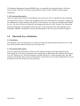
3. GUI Layer - User Input
The User Input subsystem belongs to the GUI Layer. All user inputs will be taken through the Auto
Performance Analyzer mobile application via touchscreen. The User Input subsystem will be
responsible for handling all inputs from the user through the GUI on the mobile application. Its sole
responsibilities are to capture the inputs from the user, create and package a Java class object to send to
the I/O Controller. This subsystem contains the following modules: Button Listener, and Package.
Types of inputs include:
Vehicle information from drop down list(Make/Model/Year)
List of parameters to be selected via check boxes, monitored, and/or displayed (MPH, RPM,
Temperature, etc…)
User controls (operational and configuration controls)
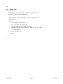
Figure 3 - 1 Button Listener module
3.1
Button Listener
3.1.1 Prologue
This module captures user input once on-screen buttons are pressed. Each button will be programmed to
do a specific job (i.e. display next/previous screen, create object, update variables, etc…).
3.1.2 Interfaces
Interfaces
Android Device (touchscreen)
Package(User Input) module
Information Required
User Input (button pressed)
Information Returned
Captured user inputs
Table 3 - 1 Button Listener module interfaces
10/04/2013
page 7
Overdrive
3.1.3 External Data Dependencies
External Interfaces – This subsystem will use the mobile device’s touchscreen for input.
3.1.4
N/A
Internal Data Dependencies
3.1.5 Psuedo-Code
<?xml version="1.0" encoding="utf-8"?>
<LinearLayout xmlns:android="http://schemas.android.com/apk/res/android"
xmlns:tools="http://schemas.android.com/tools"
android:layout_width="match_parent"
android:layout_height="match_parent"
android:orientation="horizontal">
<EditText android:id="@+id/edit_message"
android:layout_weight="1"
android:layout_width="0dp"
android:layout_height="wrap_content"
android:hint="@string/edit_message" />
<Button
android:layout_width="wrap_content"
android:layout_height="wrap_content"
android:text="@string/button_send" />
</LinearLayout>
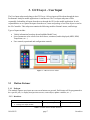
Figure 3 - 2 Package module (User Input)
3.2
Package (User Input)
3.2.1 Prologue
10/04/2013
page 8
Overdrive
This module will create a Java class object containing a particular vehicle’s information stored in
various arrays and variables.
3.2.2
Interfaces
Interfaces
Information Required
Button Listener module
Route (I/O Controller) module
Captured user input
Information Returned
Java class object
Table 3 – 2 Package (User Input) module interfaces
3.2.3
N/A
External Data Dependencies
3.2.4 Internal Data Dependencies
This module requires the captured user input provided by the Button Listener module.
3.2.5 Psuedo-Code
public class Run {
private static int routingFlag
private Date startTime
private static String Make
private static String Model
private static int Year
private int Rate
private int[] Selected_parameters
public getFlag() {
}
}
10/04/2013
page 9
Overdrive
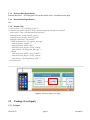
4. GUI Layer – I/O Controller
The I/O Controller subsystem belongs to the GUI Layer. This subsystem will determine where the data
(Java class object) will eventually go. It will also control the flow of data coming to and from the Event
Manager Layer. This subsystem contains the following module(s): Route.
Figure 4 – 1 Route module (I/O Controller)
4.1
Route (I/O Controller)
4.1.1 Prologue
This module will determine where the Java class object will go by reading the flag variable associated
with that object. The module will then either pass to the Presentation subsystem or the GUI Event
Handler subsystem.
4.1.2
Interfaces
Interfaces
Information Required
Package(User Input) module
Display module
Route (GUI Event Handler) module
Java class object
Information Returned
Java class object
Table 4 – 1 Route (I/O Controller) module interfaces
4.1.3 External Data Dependencies
Android’s library: threads
4.1.4 Internal Data Dependencies
This module is depended on the flag variable that is in the Java Class object.
4.1.5 Psuedo-Code
//check flag
10/04/2013
page 10
Overdrive
if(flag == 0)
//pass Java class object to Display module
else,
//pass Java class object to Route (GUI Event Handler) module
10/04/2013
page 11
Overdrive
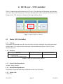
5. GUI Layer – Presentation
The Presentation subsystem belongs to the GUI Layer. This subsystem’s responsibilities are to display
the different screens/windows, and populate the list’ fields on the device’s screen through the Auto
Performance Analyzer mobile application. This subsystem contains the following module(s): Display.
Figure 5 – 1 Display module
5.1
Display
5.1.1 Prologue
This module will display the necessary screens as well as populate the fields (list of parameters and/or
DTC) through the Auto Performance Analyzer (APA) mobile application.
5.1.2
Interfaces
Interfaces
Route (I/O Controller) module
Android Device (touchscreen)
Information Required
Java class object
Information Returned
Java class object
Table 5 – 1 Display module interfaces
5.1.3 External Data Dependencies
External Interfaces – This subsystem will use the mobile device’s touchscreen for output.
5.1.4
N/A
Internal Data Dependencies
5.1.5 Psuedo-Code
Produce starting screen with text boxes and button
<?xml version="1.0" encoding="utf-8"?>
<LinearLayout xmlns:android="http://schemas.android.com/apk/res/android"
10/04/2013
page 12
Overdrive
xmlns:tools="http://schemas.android.com/tools"
android:layout_width="match_parent"
android:layout_height="match_parent"
android:orientation="horizontal">
<EditText android:id="@+id/edit_message"
android:layout_weight="1"
android:layout_width="0dp"
android:layout_height="wrap_content"
android:hint="@string/edit_message" />
<Button
android:layout_width="wrap_content"
android:layout_height="wrap_content"
android:text="@string/button_send" />
</LinearLayout>
Function to create drop down menu
public void addItemsOnSpinner2() {
spinner2 = (Spinner) findViewById(R.id.spinner2);
List<String> list = new ArrayList<String>();
list.add("list 1");
list.add("list 2");
list.add("list 3");
ArrayAdapter<String> dataAdapter = new ArrayAdapter<String>(this,
android.R.layout.simple_spinner_item, list);
dataAdapter.setDropDownViewResource(android.R.layout.simple_spinner_dropdown_item);
spinner2.setAdapter(dataAdapter);
}
Creating Check box parameter display
<?xml version="1.0" encoding="utf-8"?>
<LinearLayout xmlns:android="http://schemas.android.com/apk/res/android"
android:layout_width="fill_parent"
android:layout_height="fill_parent"
android:orientation="vertical" >
<CheckBox
android:id="@+id/chkIos"
android:layout_width="wrap_content"
android:layout_height="wrap_content"
android:text="@string/chk_ios" />
10/04/2013
page 13
Overdrive
<CheckBox
android:id="@+id/chkAndroid"
android:layout_width="wrap_content"
android:layout_height="wrap_content"
android:text="@string/chk_android"
android:checked="true" />
<CheckBox
android:id="@+id/chkWindows"
android:layout_width="wrap_content"
android:layout_height="wrap_content"
android:text="@string/chk_windows" />
<Button
android:id="@+id/btnDisplay"
android:layout_width="wrap_content"
android:layout_height="wrap_content"
android:text="@string/btn_display" />
</LinearLayout>
10/04/2013
page 14
Overdrive
6.
Event Manager Layer – GUI Event Handler
The GUI Event Handler subsystem belongs to the Event Manager layer. This subsystem handles the
flow of data between the GUI, Bluetooth, and the Event Manager layer. This subsystem contains the
following module(s): Route.
Figure 6 – 1 Route module (GUI Event Handler)
6.1
Route (GUI Event Handler)
6.1.1 Prologue
This routing module is responsible for:
6.1.2
Determining where the Java class objects needs to go by reading the flag variable associated with
that object.
Returning packaged data from the DBMS Event Handler to the GUI layer.
Sending hex-code (bytes) directly to the Run/Fetch module in the Bluetooth layer.
Interfaces
Interfaces
10/04/2013
Route (I/O Controller) module
Package(DBMS Event Handler) module
Get Runs/Store/E-Mail module
Get DTC List module
Run/Fetch module
Conversion module
Information Required
Java class object
page 15
Information Returned
Updated Java class object
Overdrive
Table 6 – 1 Route (GUI Event Handler) module interfaces
6.1.3
N/A
External Data Dependencies
6.1.4 Internal Data Dependencies
This module requires the flag variable in the Java Class object.
6.1.5 Psuedo-Code
// Create a new thread.
class NewThread implements Runnable {
Thread t;
NewThread() {
// Create a new, second thread
t = new Thread(this, "Demo Thread");
System.out.println("Child thread: " + t);
t.start(); // Start the thread
}
10/04/2013
page 16
Overdrive
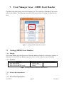
7.
Event Manager Layer – DBMS Event Handler
The DBMS subsystem belongs to the Event Manager layer. This subsystem will handle all data sent to
and from the database. This subsystem contains the following module(s): Package, Get Runs/Store/EMail.
Figure 7 – 1 Package Module (DBMS Event Handler)
7.1
Package (DBMS Event Handler)
7.1.1 Prologue
The Package module enters the data retrieved from the databases into the Java class object, packages it,
and returns it to the GUI Event Handler subsystem where it will be routed to its next destination.
7.1.2
Interfaces
Interfaces
Query History module
Query Error Code module
Route (GUI Event Handler) module
Information Required
Java class object
Data retrieved from
database
Information Returned
Updated Java class object
Table 7 – 1 Package (DBMS Event Handler) module interfaces
7.1.3
N/A
External Data Dependencies
7.1.4 Internal Data Dependencies
10/04/2013
page 17
Overdrive
This module requires the requested data fetched from either the History database or the Error Code
database.
7.1.5
N/A
Psuedo-Code
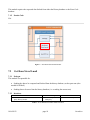
Figure 7 – 2 Get Runs/Store/E-Mail module
7.2
Get Runs/Store/E-mail
7.2.1 Prologue
This module is responsible for:
Sending the data to be compared and fetched from the history database, such as past runs (also
needed for E-Mail)
7.2.2
Sending data to be stored into the history database (i.e. recording the current run)
Interfaces
Interfaces
Information Required
Route (GUI Event Handler) module
Query History module
Java class object
Data query
Information Returned
Updated Java class object
Table 7 – 2 Get Runs/Store/E-Mail module interfaces
10/04/2013
page 18
Overdrive
7.2.3
N/A
External Data Dependencies
7.2.4
N/A
Internal Data Dependencies
7.2.5
N/A
Psuedo-Code
Figure 7 - 3 Get DTC List module
7.3
Get DTC List
7.3.1 Prologue
This module will send selected error code to the DBMS layer for comparison and retrieval of requested
data (i.e. make/model/year).
7.3.2
Interfaces
Interfaces
Route (GUI Event Handler) module
Query Error Code module
Information Required
Java class object
Data query
Information Returned
Updated Java class object
Table 7 - 3 Get DTC List module interfaces
7.3.3
External Data Dependencies
10/04/2013
page 19
Overdrive
N/A
7.3.4
N/A
Internal Data Dependencies
7.3.5
N/A
Psuedo-Code
10/04/2013
page 20
Overdrive
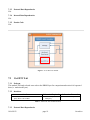
8.
Processing Layer – Data Conversion
The Data Conversion Subsystem belongs to the Processing Layer. This subsystem will do the actual
conversion calculations that it gets from the Bluetooth adapter. This subsystem contains the following
module(s): Conversion.
Figure 8 – 1 Conversion module
8.1
Conversion
8.1.1 Prologue
This module’s only responsibility is to convert the hex-code it gets from the Bluetooth adapter into
integer representation.
8.1.2
Interfaces
Interfaces
Write/Return module
Route (GUI Event Handler) module
Information Required
Java class object
Hex-code (bytes)
Information Returned
Updated Java class object
Integer data type
Table 8 – 1 Conversion module interfaces
8.1.3
N/A
External Data Dependencies
8.1.4 Internal Data Dependencies
In order to do the conversion, this module will require the hex-code (bytes) returned from the
Write/Return module.
10/04/2013
page 21
Overdrive
8.1.5 Psuedo-Code
//Read passed in hex (bytes)
//do conversion from hex to int
String hexNumber = #### //where #### is the read in hex-code
int decimal = Integer.parseInt(hexNumber, 16);
//reassign variable values
10/04/2013
page 22
Overdrive
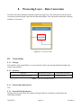
9.
Bluetooth Layer - Data Acquisition Subsystem
The Data Acquisition Subsystem belongs to the Bluetooth Layer. This subsystem will work with the
mobile device’s Bluetooth system to send requests and receive data. This subsystem contains the
following module(s): Run/Fetch, and Write/Return.
Figure 9 - 1 Run/Fetch module
9.1
Run/Fetch
9.1.1 Prologue
The Run/Fetch module will send data requests to the OBD-II adapter to be fetched.
9.1.2
Interfaces
Interfaces
Route (GUI Event Handler) module
Cancel module
Information Required
Java class object
Data query
Information Returned
Updated Java class object
Data query
Table 9 - 1 Run/Fetch module interfaces
9.1.3
N/A
External Data Dependencies
9.1.4 Internal Data Dependencies
This module requires the hex-code to lookup/fetched passed from the Route (GUI Event Handler)
module.
9.1.5
Psuedo-Code
10/04/2013
page 23
Overdrive
/* Call this from the main activity to send data to the remote device */
public void write(byte[] bytes) {
try {
mmOutStream.write(bytes);
} catch (IOException e) { }
}
Figure 9 - 2 Write/Return module
9.2
Write/Return
9.2.1 Prologue
This module receives the data it gets from the OBD-II adapter and sends it to the Processing layer,
where it will be converted into an integer type.
9.2.2
Interfaces
Interfaces
Cancel module
Conversion module
Information Required
Java class object
Hex-code (bytes)
Information Returned
Updated Java class object
Hex-code
Table 9 - 2 Write/Return module interfaces
9.2.3
N/A
External Data Dependencies
9.2.4
Internal Data Dependencies
10/04/2013
page 24
Overdrive
N/A
9.2.5 Psuedo-Code
public void run() {
byte[] buffer = new byte[1024]; // buffer store for the stream
int bytes; // bytes returned from read()
// Keep listening to the InputStream until an exception occurs
while (true) {
try {
// Read from the InputStream
bytes = mmInStream.read(buffer);
// Send the obtained bytes to the UI activity
mHandler.obtainMessage(MESSAGE_READ, bytes, -1, buffer)
.sendToTarget();
} catch (IOException e) {
break;
}
}
}
10/04/2013
page 25
Overdrive
10. Bluetooth Layer – Sync/Pair
The Sync/Pair Subsystem belongs to the Bluetooth Layer. Bluetooth synchronization and sustainability
will be handled in this subsystem. This subsystem contains the following module(s): Cancel.
Figure 10 – 1 Cancel module
10.1 Cancel
10.1.1 Prologue
This module will start or terminate the Bluetooth connection as well as maintain the connection.
10.1.2 Interfaces
Interfaces
Information Required
Run/Fetch module
Bluetooth Adapter (physical component)
Write/Return module
Java class object
Data query (hex-code)
Information Returned
Updated Java class object
Requested data (Hex-code)
Table 10 – 1 Cancel module interfaces
10.1.3 External Data Dependencies
External Interfaces – OBDLink MX Bluetooth Scan Tool attached to vehicle’s OBD-II Connecter
10.1.4 Internal Data Dependencies
This module depends on the hex-code it is passed on with by the Run/Fetch module.
10.1.5 Psuedo-Code
private class ConnectedThread extends Thread {
private final BluetoothSocket mmSocket;
10/04/2013
page 26
Overdrive
private final InputStream mmInStream;
private final OutputStream mmOutStream;
public ConnectedThread(BluetoothSocket socket) {
mmSocket = socket;
InputStream tmpIn = null;
OutputStream tmpOut = null;
/* Call this from the main activity to shutdown the connection */
public void cancel() {
try {
mmSocket.close();
} catch (IOException e) { }
}
}
10/04/2013
page 27
Overdrive
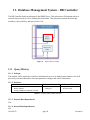
11. Database Management System – DB Controller
The DB Controller Subsystem belongs to the DBMS Layer. This subsystem will determine where to
store the data received as well as locating the desired data. This subsystem contains the following
module(s): Query History, and Query Error Code.
Figure 11 – 1 Query History module
11.1 Query History
11.1.1 Prologue
This module will be required to read/store information from a set of database that contains a list of all
previously recorded runs and its associated parameter readings, and vehicle information.
11.1.2 Interfaces
Interfaces
Information Required
Get Runs/Store/E-Mail module
History database
Package (DBMS Event Handler) module
Java class object
Data query
Information Returned
Updated Java class object
Requested data
Table 11 – 1 Query History module interfaces
11.1.3 External Data Dependencies
N/A
11.1.4 Internal Data Dependencies
N/A
10/04/2013
page 28
Overdrive
11.1.5 Psuedo-Code
@Override
public void onUpgrade(SQLiteDatabase db, int oldVersion, int newVersion) {
}
// Add public helper methods to access and get content from the database.
// Could return cursors by doing "return myDataBase.query(....)" so it'd be easy
// to create adapters for views.
}
Figure 11 - 2 Query Error Code module
11.2 Query Error Codes
11.2.1 Prologue
This module will query the Error Code database for a particular DTC for comparison. If comparison
matches, the module will return the DTC and its corresponding description.
11.2.2 Interfaces
Interfaces
Information Required
Get DTC List module
Error Code database
Package (DBMS Event Handler) module
Java class object
Data query
Information Returned
Updated Java class object
Requested data
Table 11 - 2 Query Error Codes module interfaces
10/04/2013
page 29
Overdrive
11.2.3 External Data Dependencies
N/A
11.2.4 Internal Data Dependencies
N/A
11.2.5 Psuedo-Code
@Override
public void onUpgrade(SQLiteDatabase db, int oldVersion, int newVersion) {
}
// Add public helper methods to access and get content from the database.
// Could return cursors by doing "return myDataBase.query(....)" so it'd be easy
// to create adapters for views.
}
10/04/2013
page 30
Overdrive
12. Inter-Components Data Flow
12.1 Overview
Relationship Mapping describes the data flow between each module component of the Auto
Performance Analyzer.
12.2 Data Flow Definitions
Table 12-1 (Shown below) provides a description of the data that flows between each module. Data
originating from the GUI Layer will begin with a G, Event Manager Layer will begin with E, Processing
Layer will begin with P, DBMS Layer will begin with D, and Bluetooth Layer will begin with B.
DBMS Layer
Processing Layer
Event Management Layer
GUI Layer
Layer
10/04/2013
Data
Element Description
G1
Button Pressed
G2
Send Button event
G3
Pass object to I/O Controller
G4
User interface and run object
G5
Send updated GUI Presentation to Android Device.
G6
Object
E1
Object with parameter list (hex code)
E2
Object with converted hex DTC (P301) & flag
E3
Object with converted hex DTC (P301) with fetch instruction
E4
Object with flag
E5
Object with fetch/store instructions
E6
Packaged object
E7
Return packed object I/O Controller
P1
Object with converted DTC code or parameters
D1
Return fetched object with past runs
D2
Return fetched Object with DTC (code + description)
D3
Read, compare, fetch past runs or store info
D4
Read, compare, fetch DTC (code + description)
page 31
Overdrive
Bluetooth Layer
B1
Hex code to be fetched
B2
Connect to Bluetooth adapter, send hex code, synchronize
B3
Returns Hex code, maintains connection.
B4
Returns Hex Code.
B5
Pass hex code to be converted.
Table 12 - 1 Module Component Data Flow Definitions
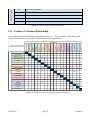
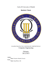
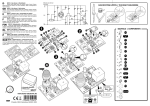
12.3 Producer-Consumer Relationship
The producer-consumer relationship is described in Figure 12 – 1 (Shown below). The producer is the
source of data element; the consumer is the destination of the data element.
Package (User Input)
Route (I/O Controller)
Bluetooth ODBII
Adapter
Cancel
G2
G3
E7
Display
G4
Route (GUI Event Handler)
G6
E6
Get Runs/Store/E-Mail
E4
Get DTC List
E2
P1
Conversion
B5
History (Database)
D3
Query History
E5
Query Error Code
D3
E3
Error Codes (Database)
Run/Fetch
Write/Return
Run/Fetch
D2
Error Codes
(Database)
History
(Database)
Conversion
Get DTC List
Get Runs/Store/EMail
Package (DBMS
Event Handler)
Route (GUI Event
Handler)
D1
G5
G1
Package (DBMS Event Handler)
Consumers
Query Error Code
Button Listener
Query History
Android Device
Display
Route (I/O
Controller)
Package (User
Input)
Button Listener
Producer-Consumer Relationship
Mapping for Modules Components
Android Device
Producers
D4
D4
E1
Write/Return
B4
Cancel
B1
Bluetooth ODBII Module
B3
B2
Figure 12 - 1 Producer-Consumer Relationship mapping of Components
10/04/2013
page 32
Overdrive
13. Quality Assurance
13.1 Test Plans and Procedures
The System Detailed Design will be tested by team Overdrive to verify that the Auto Performance
Analyzer fulfills all of the requirements laid out in the System Requirements Specification and in the
Architectural Design Specification. Each component and subsystem will be designed to work
independently and this independence will allow each module to be tested individually. Then it will be
integrated to the final application which then it will be tested again to make sure there will not be
integrity issues.
13.2 Module/Unit Testing
13.2.1 GUI Layer
This layer will get the user’s input via the mobile device’s screen; pass the parameters list to the Event
Management layer. It will also be in charge of displaying the information obtained from the Event
Manager layer.
User Input Subsystem Test
The tests for this subsystem will verify that the user actions for the buttons will be captured by the
application and that this subsystem will create and package a Java class object with the vehicle’s
information and desired parameters and options to send to the I/O Controller subsystem.
I/O Controller Subsystem Test
This subsystem will be tested by verifying that the object that is passed by the User Input Subsystem
will be routed to the destination module which could be either the Mobile Device Screen via the
Presentation subsystem or the Event Manager Layer.
Presentation Subsystem Test
The test for the this subsystem will verify that all of the different screens and graphs of the application
will show correctly and without distortions of any kind, neither cut portions of the screens when the
application is run in devices with a different screen size. The tests will also check that the information
will be extracted from the object and populated in the right fields. Additional Tests will verify that the
actions from the buttons pressed by the user will be reflected and directed to the proper screens.
10/04/2013
page 33
Overdrive
13.2.2 Event Manager Layer
The Event Manager layer will be in charge of managing and routing the information obtained from all
the other layers.
GUI Event Handler Test
This subsystem will be tested by verifying that the object passed to it from the other layers or
subsystems will be directed to the proper destination subsystem, this will include passing the parameter
hex code to the Bluetooth Layer
DBMS Event Handler Test
The test for this subsystem will verify that the information obtained from the Database will be packaged
and sent to the GUI Layer. Another test will verify that it will send the DTC code to query the database.
This will include obtaining information about current runs to be stored in the database or past runs to be
read from the database.
13.2.3 Processing Layer
The Processing layer will receive the parameters list from the Event Manager layer or actual parameter
data from the Bluetooth Layer and code/decode the information, and will perform processing if
necessary and then, formatting the data into decimal form.
Data Conversion Subsystem Test
This subsystem will be tested by making sure that performs the proper conversion from hex form to
decimal form, from the bytes passed to it from the Bluetooth Layer.
13.2.4 Bluetooth Layer
The Bluetooth Layer will send and receive data to and from the OBDLink MX Bluetooth Scan Tool. Such
data will be passed to the Processing Layer to be processed.
Data Acquisition Subsystem Test
This subsystem will be tested by verifying that sends and receives data from the Bluetooth adapter. The
information sent will be the hex code (one byte) for the parameter of interest and the received data will
be from one to four bytes of the data for such parameter.
Sync/Pair Subsystem Test
10/04/2013
page 34
Overdrive
This subsystem will be tested by verifying that the connection will not be interrupted while using the
application and the transfer of information between the application and the Bluetooth adapter. The other
test will verify that the Bluetooth connection will be properly closed upon exiting the application.
13.2.5 DBMS Layer
The DBMS Layer is responsible for storing and retrieving the data in a spreadsheet or a file in the form
of a table or comma separated spreadsheet. This layer will also be responsible for retrieval of the
Trouble Code Description information.
DB Controller Subsystem Test
The tests for this subsystem will verify that the vehicle parameter’s information will be stored and
retrieved from the History database. The other test will make sure that the correct DTC description
information will be retrieved from the Error Code Database
13.3 Integration Testing Approach
The Integrity testing will verify proper operation of all of the functions and menus of the Auto
Performance Analyzer Application to ensure that it will satisfy all of the requirements from the customer
and that it will not be interlayer compatibility issues when integrated to the main application.
13.3.1 GUI Layer Testing
Verify that any user input and button pressings will be recognized by the User Input Subsystem
Verify that the vehicle’s object information will be passed to the event manager layer
Verify that the object with the parameters updated received from the event manager layer will be
displayed correctly and without noticeable lags in the mobile device’s screen
Verify that the Graphs generated will be rendered accurately in the mobile device’s screen
13.3.2 Event Manager Layer
Verify that the object with the vehicle’s parameters will be passed to the GUI Layer and to the
DBMS Layer
Verify that the vehicle’s history data will be retrieved from the Data Base Layer and passed to
the GUI Layer
Verify that the parameters hex code will be passed to the Bluetooth layer
Verify that the converted DTC will be sent to the DBMS Layer
10/04/2013
page 35
Overdrive
13.3.3 Processing Layer Testing
Verify that the vehicle’s parameter information will be converted from Hex to Decimal
Verify that the DTC Hex code received from the Bluetooth Layer will be translated to ASCII
13.3.4 Bluetooth Layer
Verify that the Bluetooth connection is established and not lost during the transfer of data
Verify that the data is sent to and received from the Bluetooth adapter
Verify that the Bluetooth connection will be closed when the user exits the application
13.3.5 DBMS Layer
Verify that the vehicle’s actual parameter data will be saved to the History Data Base
Verify that the vehicle’s history parameter data will be retrieved from the History Data Base
Verify that the vehicle’s DTC Information will be retrieved from the Error Code Data Base
13.4 System Verification Testing
13.4.1 GUI Layer Testing
Testing of this layer will verify that the GUI layer will be able to pass the user selection list to the Event
Manager layer, and also be able to display the information obtained from the same layer.
13.4.2 Event Manager Layer
This layer will be tested to make sure that it will correctly route the information obtained from the
processing layer or the Storage Management layer. Next, that data is properly format for the GUI Layer.
Last is that the data is not corrupted when passes to and from the GUI to the Processing Layer and to the
DBMS Layer.
10/04/2013
page 36
Overdrive
13.4.3 Processing Layer Testing
The tests for this layer will verify that receives the parameters list from the GUI layer and translates this
list into a command stream of the proper OBD-II codes that will be passed to the Bluetooth layer. There
will also be tests that will verify that the data obtained from the car by the Bluetooth layer will be
correctly translated to decimal format.
13.4.4 Bluetooth Layer
This layer will be tested within the tests performed for the Processing Layer. That is, it will verify that
the application can communicate to the OBD-II adapter and received information from it, and that it will
not lose connection to the OBD-II adapter.
13.4.5 DBMS Layer
The tests for this layer will include obtaining the data from the processing layer and verify that the data
will preserve its integrity when is formatted and stored in the spreadsheet. Additional tests will be
included to verify that the Storage management layer deliver the right information from the Diagnostic
Trouble Code database to the GUI layer through the DBMS Handler in the Event Manager Layer.
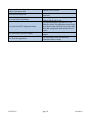
13.5 Test Cases
Test Case
User Connects Bluetooth Adapter to Car’s
OBD-II port. Ignition key is off
User turns the ignition key to ON position
User pairs the Bluetooth adapter to the mobile
device
User Loads the mobile application
User enters the vehicle’s information and
selected parameters to monitor
User records the actual vehicle’s parameter
data
10/04/2013
Expected Result
LEDs on the Bluetooth adapter will not lit
LEDs on the Bluetooth adapter will blink
momentarily and then the power LED will
remain lit while the Bluetooth LED will
remain blinking and the Activity LED will be
off
The power and Bluetooth LEDs will stay lit
and the Activity LED will stay off
The Bluetooth will not be interrupted and the
application loads the initial screen
Changes are reflected in the GUI screen and
the vehicles information object is created
Vehicle’s file is created in the database and
the data is saved to the file and displayed in
the GUI screen
page 37
Overdrive
User stops the recording of the actual
vehicle’s parameter data
User selects a history run
User selects the email button
User selects the DTC diagnostic button
User selects the Clear DTC button
User Exits the application
Vehicle’s file is closed
Vehicle’s file is retrieved from the History
Data Base
Screen pops up to enter the destination email
address and the file is sent
The Bluetooth adapter gets the DTC code
from the vehicle, the application retrieves the
description of the code from Error codes Data
Base and is displayed in the mobile device’s
screen
Clear DTC code is sent to the Bluetooth
adapter
The application closes the Bluetooth
connection before closing
Table 13 – 1 Test Cases
10/04/2013
page 38
Overdrive
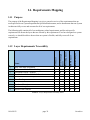
14. Requirements Mapping
14.1 Purpose
The purpose of the Requirement Mapping is to give a general overview of the requirements that our
team specified in our System Requirements Specification document, and to demonstrate that our System
Architecture fully covers and accounts for all of our requirements.
The following table contains all of our architecture related requirements, and for each specific
requirement will dictate the layers that are affected by this requirement. If we have designed our system
correctly, we should be able to observe that our system is flexible, and fully covers all of our
requirements.
X
X
X
X
X
X
X
X
X
Bluetooth Layer
Real-Time Data Acquisition
Performance Mode - Select Readings
Performance Mode - Monitor
Troubleshoot Mode - Vehicle Information
Troubleshoot Mode - Comparison
Store Readings
Database (Trouble Codes)
Database (History)
Real-Time Output
Reliable Data Transfer
DBMS Layer
3.1
3.2
3.3
3.4
3.5
3.6
3.7
3.8
5.1
5.2
Processing Layer
#
Name
Event Manager
Layer
GUI Layer
14.2 Layer Requirements Traceability
X
X
X
X
X
X
X
X
X
X
X
X
X
X
X
X
Table 14 - 1 Layer Requirements Traceability matrix
10/04/2013
page 39
Overdrive
Button Listener
X
X
Package
X
X
Route
X
Display
Route
Package
Get
Runs/Store/Email
X
X
X
Run/Fetch
5.2 Reliable Data Transfer
5.1 Real-Time Output
3.8 Database (History)
3.7 Database (Error Code)
X
X
X
X
X
X
X
X
X
X
X
X
X
X
X
X
X
X
X
X
X
X
X
X
X
X
X
Query Error Code
Conversion
3.6 Store Readings
X
X
Get DTC list
Query History
X
3.5 Troubleshoot Mode - Comparison
3.4 Troubleshoot Mode - Vehicle
Information
3.3 Performance Mode - Monitor
3.2 Performance Mode - Select Readings
3.1 Real-Time Data Acquisition
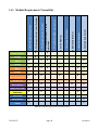
14.3 Module Requirements Traceability
X
X
X
X
X
X
X
X
X
X
X
Write/Return
X
X
X
Cancel
X
X
Table 14 - 2 Module Requirements Traceability matrix
10/04/2013
page 40
Overdrive
15. Acceptance Plan
15.1 Overview
The acceptance plan will outline the minimum requirements that must be fulfilled for the Auto
Performance Analyzer (APA) to be accepted as a completed project. These are the requirements
mirrored from the System Requirements
15.2 Packaging and Installation
This section describes the packaging requirements for Auto Performance Analyzer (APA). The
requirements include the user manual, OBDLink MX Bluetooth Scan Tool, android market submission.
15.2.1 User Manual
Description: The system shall be packaged with a user manual cd explaining how to use APA.
Source: Overdrive
Constraints: The manual will be produced as a pdf file and written in English.
Standards: None
Priority: 1 - Critical
15.2.2 OBDLink MX Bluetooth Scan Tool
Description: The system will include the OBDLink MX Bluetooth Scan Tool.
Source: ScanTool.Net
Constraints: Budget
Standards: Functionality must be tested before packaging.
Priority: 3 - Medium
15.2.3 Android Application Store Submission
Description: APA will be available in the Android Market as a free download.
Source: Overdrive
Constraints: Guidelines to publish an application in the Android Market
Standards: None
Priority: 2- High
15.2.4 OBDLink MX Bluetooth Scan Tool Installation
Description: The quick start guide will include instructions to install the scan tool
Source: Typical location of the vehicle’s OBD-II port
Constraints: Vehicle’s manufacturers
10/04/2013
page 41
Overdrive
Standards: None
Priority: 1 - Critical
15.3 Acceptance Testing
The Auto Performance Analyzer will be tested in several ways to verify that it meets the acceptance
criteria defined below. These tests will include module, subsystem, layer, integration, and overall system
testing. More details on these tests will be provided in the System Test Plan document.
15.4 Acceptance Criteria
15.4.1 GUI Layer
This layer will get the user’s input via the mobile device’s screen; pass the parameters list to the Event
Management layer. It will also be in charge of displaying the information obtained from the Event
Manager layer.
User Input Subsystem Acceptance Criteria
After the tests from the model/unit testing are run the acceptance criteria will ensure the Java
class object with the vehicle’s information and desired parameters and options are packaged
correctly before being sent to the I/O controller subsystem.
I/O Controller Subsystem Acceptance Criteria
The acceptance criteria for this layer will ensure that during multiple test runs that the correct
flags have been assigned and route the data to the correct module e.g. display module or routing
module in the GUI Event handler subsystem.
Presentation Subsystem Acceptance Criteria
The acceptance criteria for this layer will ensure that screens show correct information that is
extracted from the object and populated in the right fields. Also the buttons and information
entered take the user to the logical next screen.
15.4.2 Event Manager Layer
The Event Manager layer will be in charge of managing and routing the information obtained from all
the other layers except the Bluetooth Layer.
GUI Event Handler Acceptance Criteria
The acceptance criteria for this subsystem will ensure that object is routed correctly to the next
logically module by the flag assigned in previous modules and include the parameter hex code to
the Bluetooth Layer.
DBMS Event Handler Acceptance Criteria
The acceptance criteria for this subsystem is very similar to the GUI event handler subsystem
and it will ensure that object are routed correctly to the next logically module by the flag
10/04/2013
page 42
Overdrive
assigned in previous modules. The acceptance criteria is also ensured by checking the database
to ensure that the package data in the Run object is stored correctly after being passed to the
query database module.
15.4.3 Processing Layer
The Processing layer will receive the parameters list from the Event Manager layer or actual parameter
data from the Bluetooth Layer and code/decode the information, and will perform processing and the
formatting into decimal form.
Data Conversion Subsystem Acceptance Criteria
The acceptance criteria for this subsystem will ensure from the bytes passed from Bluetooth
module that they are converted correctly from hexadecimal to decimal based on hand
calculations.
15.4.4 DBMS Layer
The DBMS Layer is responsible for storing the data in a spreadsheet or a file in the form of a table. This
layer will also be responsible for retrieval of the Trouble Code Description information.
DB Controller Subsystem Acceptance Criteria
The acceptance criteria for this subsystem will ensure that the vehicle parameter’s information is
stored and retrieved correctly from the History database. The other acceptance criteria will
ensure that the correct DTC description information is retrieved from the error code database.
15.4.5 Bluetooth Layer
The Bluetooth Layer will send and receive data to and from the Bluetooth Scan Tool. Such data will be
passed to the Processing Layer to be processed.
Data Acquisition Subsystem Acceptance Criteria
The acceptance criteria for this subsystem will ensure that the information from the Bluetooth
module is the hex code (one byte) for the parameter of interest and the received data is from one
to four bytes of the data for such parameter using the simulator to retrieve a known value.
Sync/Pair Subsystem Test
The acceptance criteria for this subsystem will ensure that the connection is not interrupted while
using the application and the transfer of information between the application and the Bluetooth
adapter. The other acceptance criteria will ensure that the Bluetooth connection is properly
closed upon exiting the application and when a run is complete.
10/04/2013
page 43
Overdrive
16. Hardware Components
16.1 Overview
This section will list the necessary hardware components as well as its purpose, specifications, and
interfaces, needed to run the Auto Performance Analyzer mobile application.
16.2 OBDLink MX Bluetooth Scan Tool
16.2.1 Purpose
The purpose of this adapter is to send and retrieve hex-codes from the vehicle’s on-board diagnostic
(OBD) system.
16.2.2 Specifications
Dimensions
Weight
Operating Ambient Temperature
Supply Voltage
Operating Voltage
Operating Humidity
0.91”(23mm) x 1.97”(51mm) x 1.77”(45mm)
1.2 oz. (33 g.)
-4º to 131º F (-20º to 55º C)
7VDC to 40VDC
8-18V DC
10 to 85% (non-condensing)
Table 16 - 1 Operating Specifications for OBDLink MX Bluetooth Scan Tool
16.2.3 Interfaces
This adapter is connected to the vehicle’s OBD-II connector (usually found under the steering wheel).
10/04/2013
page 44
Overdrive
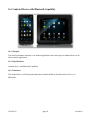
16.3 Android Device with Bluetooth Capability
16.3.1 Purpose
The Auto Performance Analyzer is an Android application, thus will require an Android device to be
able to run the application.
16.3.2 Specifications
Android device with Bluetooth Capability
16.3.3 Interfaces
The Android device will be paired/synchronized with the OBDLink MX Bluetooth Scan Tool, via
Bluetooth.
10/04/2013
page 45
Overdrive
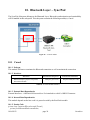
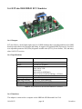
16.4 ECUsim 2000 OBD-II ECU Simulator
16.4.1 Purpose
ECUsim 2000 is a small, lightweight, entry level OBD simulator that is an indispensable tool for OBD
hardware and software development and testing. It supports all legislated OBD-II protocols, fixed and
user adjustable parameter IDs (PIDs), diagnostic trouble codes (DTCs), freeze frames, VIN, and many
other SAE J1979 services.
16.4.2 Specifications
5.0 x 3.0 x 1.12 in (127 x 76.2 x 28.4 mm)
Dimensions
Weight
Power
OBD Protocols
2.5 oz (70.8 g)
12 VDC @ 2A (max)
SAE J1850 PWM
SAE J1850 VPW
ISO 9141-2
ISO 14230-4 (KWP2000)
ISO 15765-4 (CAN 250/500 kbps, 11/29 bit)
PC Port
USB Type B
Operating Temperature -4° to 131°F (-20° to 55°C)
Operating Humidity
10 to 85%, non-condensing
Storage Temperature
-40° to 185°F (-40° to 85°C)
Storage Humidity
5 to 90% non-condensing
Table 16 - 2 Specifications for ECUsim 2000 OBD-II ECU Simulator
16.4.3 Interfaces
This adapter is connected to a computer or the OBDLink MX Bluetooth Scan Tool.
10/04/2013
page 46
Overdrive
10/04/2013
page 47
Overdrive
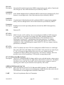
Appendix A: Acronym/Glossary
APA:
Description:
Auto Performance Analyzer
An Android mobile application currently in development by team Overdrive.
ADS:
Architectural Design Specification
CAN:
Description:
Controller Area Network
CAN is a serial bus protocol to connect individual systems and sensors as an alternative
to conventional multi-wire looms. It allows automotive components to communicate on a
single or dual-wire networked data bus up to 1Mbps.
COTS:
Description:
Commercial off-the-Shelf
An adjective that describes software or hardware products that is ready-made and
available for sale to the general public.
DBMS:
Database Management System
DDS:
Detailed Design Specification
DTC:
Description:
Diagnostic Trouble Code (Also referred to as Trouble Code or Error Code)
An alphanumeric value that corresponds to a particular type of fault, detected by the
OBD system.
ECUsim 2000 OBD-II ECU Simulator
Description: ECUsim 2000 is a small, lightweight, entry level OBD simulator that is an indispensable
tool for OBD hardware and software development and testing. It supports all legislated
OBD-II protocols, fixed and user adjustable parameter IDs (PIDs), diagnostic trouble
codes (DTCs), freeze frames, VIN, and many other SAE J1979 services.
ELM327:
Description:
A programmed microcontroller produced by ELM Electronics for translating the onboard diagnostics (OBD) interface found in most modern cars.
GUI:
Graphical User Interface
I/O:
Input/Output
OBD:
On-Board Diagnostic System
OBD-II:
Description:
On-Board Diagnostics System
Updated On-Board Diagnostics standard effective in cars sold in the US after 1-1-96.
OBD-II, a new standard introduced in the mid-'90s, provides almost complete engine
control and also monitors parts of the chassis, body and accessory devices, as well as the
diagnostic control network of the car.
10/04/2013
page 48
Overdrive
ISO 9141:
Description:
International Standards Organization OBDII communication mode, used by Chrysler and
most foreign cars. One of three hardware layers defined by OBD II
J1850PWM:
Description: (Pulse Width Modulated) SAE-established OBD II communication standard used by Ford
domestic cars and light trucks. One of three hardware layers defined by OBD II
J1850VPW:
Description: (Variable Pulse Width Modulated) SAE-established OBD II communication standard
used by GM cars and light trucks. One of three hardware layers defined by OBD II
Parameters:
Description: Readings on scan tools representing functions measured by OBD II and proprietary
readings
PID:
STN1110:
Description:
STN1170:
Description:
Parameter ID
STN1110 is the world’s smallest, lowest cost multiprotocol OBD to UART interpreter
IC. It provides an easy means of accessing vehicle data, including diagnostic trouble
codes, MIL status, VIN, Inspection and Maintenance (I/M) information, In-use
Performance Tracking (IPT), and hundreds of real-time parameters. To maintain
compatibility with existing applications, STN1110 has full support for the ELM327
command set, while outperforming the original ELM327 IC in every category: stability,
performance, and features.
STN1170 combines the entire STN1110 (multiprotocol OBD-II) feature set with Single
Wire CAN (SW-CAN) and Medium Speed CAN (MS-CAN) protocols in a single 44-pin
IC. SW-CAN protocol support allows your device to access, monitor and issue
commands on vehicles utilizing GM’s proprietary CAN network. Similarly, MS-CAN
provides access to Ford’s proprietary CAN network on supporting models.
STN1170 Bluetooth OBD-II Adapter:
Description: The STN1170 Bluetooth OBD-II adapter enables you to read and monitor various sensors
built into newer (1996-present) cars, light-trucks, and some heavy-trucks too. The adapter
also allows you to read and clear trouble codes from the engine computer to assist in
repairing your vehicle to pass emissions tests required by some states.
OBDLink MX Bluetooth Scan Tool
Description: Same functionalities as the STN1170 Bluetooth OBD-II Adapter. The OBDLink MX
Bluetooth is the world’s fastest on-board diagnostics (OBD) interface that works with all
1996 and newer cars and light trucks sold in the United States.
UART:
10/04/2013
Universal Asynchronous Receiver/Transmitter
page 49
Overdrive
Description:
10/04/2013
A piece of computer hardware that translates data between parallel and serial forms.
Every computer contains a UART to manage the serial ports, and some internal modems
have their own UART.
page 50
Overdrive
Appendix B: Pseudo-Codes
public class DataBaseHelper extends SQLiteOpenHelper{
//The Android's default system path of your application database.
private static String DB_PATH = "/data/data/YOUR_PACKAGE/databases/";
private static String DB_NAME = "myDBName";
private SQLiteDatabase myDataBase;
private final Context myContext;
/**
* Constructor
* Takes and keeps a reference of the passed context in order to access to the application assets and
resources.
* @param context
*/
public DataBaseHelper(Context context) {
super(context, DB_NAME, null, 1);
this.myContext = context;
}
/**
* Creates a empty database on the system and rewrites it with your own database.
* */
public void createDataBase() throws IOException{
boolean dbExist = checkDataBase();
if(dbExist){
//do nothing - database already exist
}else{
//By calling this method and empty database will be created into the default system path
//of your application so we are gonna be able to overwrite that database with our database.
this.getReadableDatabase();
try {
copyDataBase();
} catch (IOException e) {
10/04/2013
page 51
Overdrive
throw new Error("Error copying database");
}
}
}
/**
* Check if the database already exist to avoid re-copying the file each time you open the application.
* @return true if it exists, false if it doesn't
*/
private boolean checkDataBase(){
SQLiteDatabase checkDB = null;
try{
String myPath = DB_PATH + DB_NAME;
checkDB = SQLiteDatabase.openDatabase(myPath, null,
SQLiteDatabase.OPEN_READONLY);
}catch(SQLiteException e){
//database does't exist yet.
}
if(checkDB != null){
checkDB.close();
}
return checkDB != null ? true : false;
}
/**
* Copies database from local assets-folder to the just created empty database in the
* system folder, from where it can be accessed and handled.
* This is done by transfering bytestream.
* */
private void copyDataBase() throws IOException{
//Open local db as the input stream
InputStream myInput = myContext.getAssets().open(DB_NAME);
// Path to the just created empty db
String outFileName = DB_PATH + DB_NAME;
//Open the empty db as the output stream
10/04/2013
page 52
Overdrive
OutputStream myOutput = new FileOutputStream(outFileName);
//transfer bytes from the inputfile to the outputfile
byte[] buffer = new byte[1024];
int length;
while ((length = myInput.read(buffer))>0){
myOutput.write(buffer, 0, length);
}
//Close the streams
myOutput.flush();
myOutput.close();
myInput.close();
}
public void openDataBase() throws SQLException{
//Open the database
String myPath = DB_PATH + DB_NAME;
myDataBase = SQLiteDatabase.openDatabase(myPath, null,
SQLiteDatabase.OPEN_READONLY);
}
@Override
public synchronized void close() {
if(myDataBase != null)
myDataBase.close();
super.close();
}
@Override
public void onCreate(SQLiteDatabase db) {
}
@Override
public void onUpgrade(SQLiteDatabase db, int oldVersion, int newVersion) {
}
// Add public helper methods to access and get content from the database.
// Return cursors by doing "return myDataBase.query(....)" so it'd be easy
// to create adapters for views.
10/04/2013
page 53
Overdrive
}
// Functionality to use the database
DataBaseHelper myDbHelper = new DataBaseHelper();
myDbHelper = new DataBaseHelper(this);
try {
myDbHelper.createDataBase();
} catch (IOException ioe) {
throw new Error("Unable to create database");
}
try {
myDbHelper.openDataBase();
}catch(SQLException sqle){
throw sqle;
}
10/04/2013
page 54
Overdrive
Appendix C: Generic Diagnostic Trouble Codes
Generic Powertrain Trouble Codes: (P0xxx, P2xxx, P34xx - P39xx)
P00xx - Fuel and Air Metering and Auxiliary Emission Controls.
P0100-P0199 – Fuel and Air Metering
P0200-P0299 – Fuel and Air Metering (Injector Circuit)
P0300-P0399 – Ignition System or Misfire
P0400-P0499 – Auxiliary Emissions Controls
P0500-P0599 – Vehicle Speed Controls and Idle Control System
P0600-P0699 – Computer Output Circuit
P0700-P0899 – Transmission
Generic Body Trouble Codes:
*(As of 2005, generic body codes have not been completely defined by auto-makers.)
Generic Chassis Codes:
(B0xxx, B3xxx)
(C0xxx, C3xxx)
*(As of 2005, generic chassis codes have not been completely defined by auto-makers.)
Generic Network Trouble Codes:
(U0xxx, U3xxx)
Generic Powertrain Trouble Codes
Generic Body Trouble Codes *Not completely defined
P0001
P0002
P0003
Fuel Volume Regulator Control Circuit/Open
Fuel Volume Regulator Control Circuit Range/Performance
Fuel Volume Regulator Control Circuit Low
B0001
B0004
B0005
B0016
P0004
Fuel Volume Regulator Control Circuit High
P0005
Fuel Shutoff Valve "A" Control Circuit/Open
P0006
Fuel Shutoff Valve "A" Control Circuit Low
P0007
Fuel Shutoff Valve "A" Control Circuit High
P0008
Engine Position System Performance
P0009
P0010
Engine Position System Performance
"A" Camshaft Position Actuator Circuit
"A" Camshaft Position - Timing Over-Advanced or System
Performance
B0017
B0018
B0022
B0024
B0026
P0011
B0028
B0029
B0030
P0012
P0013
P0014
P0015
P0016
"A" Camshaft Position - Timing Over-Retarded
"B" Camshaft Position - Actuator Circuit
"B" Camshaft Position - Timing Over-Advanced or System
Performance
"B" Camshaft Position - Timing Over-Retarded
Crankshaft Position - Camshaft Position Correlation
10/04/2013
PCM Discrete Input Speed Signal Error
PCM Discrete Input Speed Signal Not Present
In Park Switch Circuit Malfunction
RF/Passenger Frontal Deployment Loop (Single Stage or Stage 1)
Resistance Low
RF/Passenger Frontal Deployment Loop (Single Stage or Stage 1)
Open
RF/Passenger Frontal Deployment Loop (Single Stage or Stage 1)
Short to Ground/Voltage Out of Range
LF/Driver Frontal Deployment Loop (Single Stage or Stage 1)
Resistance Low
LF/Driver Frontal Deployment Loop (Single Stage or Stage 1)
Short to Ground/Voltage Out of Range
LF/Driver Frontal Deployment Loop (Single Stage or Stage 1)
Open
RF/Passenger Side Deployment Loop Resistance Low
RF/Passenger Side Deployment Loop Open
B0035
B0036
RF/Passenger Side Deployment Loop Short to Ground/Voltage
Out of Range
ADS Closed/Shorted to Ground
ADS Open/Missing/Shorted to Battery
B0037
B0038
AUX switch closed/shorted to ground
AUX switch open/shorted to battery
page 55
Overdrive
P0017
P0018
P0019
P0020
P0024
P0025
P0026
Crankshaft Position - Camshaft Position Correlation
Crankshaft Position - Camshaft Position Correlation
Crankshaft Position - Camshaft Position Correlation
"A" Camshaft Position Actuator Circuit
"A" Camshaft Position - Timing Over-Advanced or System
Performance
"A" Camshaft Position - Timing Over-Retarded
"B" Camshaft Position - Actuator Circuit
"B" Camshaft Position - Timing Over-Advanced or System
Performance
"B" Camshaft Position - Timing Over-Retarded
Intake Valve Control Solenoid Circuit Range/Performance
P0027
P0028
P0029
Exhaust Valve Control Solenoid Circuit Range/Performance
Intake Valve Control Solenoid Circuit Range/Performance
Exhaust Valve Control Solenoid Circuit Range/Performance
P0030
P0031
P0032
P0033
P0034
P0035
P0036
P0037
P0038
P0046
P0047
P0048
HO2S Heater Control Circuit
HO2S Heater Control Circuit Low
HO2S Heater Control Circuit High
Turbo Charger Bypass Valve Control Circuit
Turbo Charger Bypass Valve Control Circuit Low
Turbo Charger Bypass Valve Control Circuit High
HO2S Heater Control Circuit
HO2S Heater Control Circuit Low
HO2S Heater Control Circuit High
Turbo/Super Charger Bypass Valve Control Circuit
Range/Performance
O2 Sensor Signals Swapped Bank 1 Sensor 1/ Bank 2 Sensor 1
O2 Sensor Signals Swapped Bank 1 Sensor 2/ Bank 2 Sensor 2
HO2S Heater Control Circuit
HO2S Heater Control Circuit Low
HO2S Heater Control Circuit High
Turbo/Super Charger Boost Control Solenoid Circuit/Open
Turbo/Super Charger Boost Control Solenoid Circuit
Range/Performance
Turbo/Super Charger Boost Control Solenoid Circuit Low
Turbo/Super Charger Boost Control Solenoid Circuit High
P0049
P0050
Turbo/Super Charger Turbine Overspeed
HO2S Heater Control Circuit
P0051
HO2S Heater Control Circuit Low
P0052
P0053
P0054
P0055
P0056
P0057
P0058
P0059
P0060
P0061
P0062
P0063
P0064
P0065
P0066
P0067
P0068
P0069
P0070
P0071
P0072
HO2S Heater Control Circuit High
HO2S Heater Resistance
HO2S Heater Resistance
HO2S Heater Resistance
HO2S Heater Control Circuit
HO2S Heater Control Circuit Low
HO2S Heater Control Circuit High
HO2S Heater Resistance
HO2S Heater Resistance
HO2S Heater Resistance
HO2S Heater Control Circuit
HO2S Heater Control Circuit Low
HO2S Heater Control Circuit High
Air Assisted Injector Control Range/Performance
Air Assisted Injector Control Circuit or Circuit Low
Air Assisted Injector Control Circuit High
MAP/MAF - Throttle Position Correlation
Manifold Absolute Pressure - Barometric Pressure Correlation
Ambient Air Temperature Sensor Circuit
Ambient Air Temperature Sensor Range/Performance
Ambient Air Temperature Sensor Circuit Low
P0021
P0022
P0023
P0039
P0040
P0041
P0042
P0043
P0044
P0045
B0040
B0041
B0045
B0051
B0053
LF/Driver Side Deployment Loop Resistance Low
LF/Driver Side Deployment Loop Open
LF Side Deploy Loop Short to Ground/Voltage Out of Range
Deployment Commanded
Deployment Commanded with Loop Malfunctions Present
B0057
B0058
B0059
RF/Passenger Pretensioner Deployment Loop Resistance Low
RF/Passenger Pretensioner Deployment Loop Open
RF/Passenger Pretensioner Deployment Loop Short to
Ground/Voltage Out of Range
LF/Driver Pretensioner Deployment Loop Resistance Low
LF/Driver Pretensioner Deployment Loop Open
LF/Driver Pretensioner Deployment Loop Short to
Ground/Voltage Out of Range
Supplemental Deployment Loop #1 Resistance Low
Supplemental Deployment Loop #1 Open
Supplemental Deployment Loop #1 Short to Ground/Voltage
Out of Range
LF/Driver SIS Malfunction
RF/Passenger SIS Malfunction
Incorrect LF/Driver SIS Installed
Discard LF/Driver SIS
Incorrect RF/Passenger SIS Installed
Discard RF/Passenger SIS
Supplemental Deployment Loop #2 Resistance Low
Supplemental Deployment Loop #2 Open
Supplemental Deployment Loop #2 Short to Ground/Voltage
Out of Range
Active switch voltage out of range
Active switch: wrong state
PPS passenger detection error
PPS/CPS self-test malfunction
CPS childseat detection error
SDM-PPS/CPS mismatch malfunction
Right Panel Discharge Temperature Fault
B0064
B0065
B0066
B0073
B0074
B0075
B0077
B0078
B0079
B0080
B0081
B0082
B0086
B0087
B0088
B0090
B0091
B0092
B0093
B0094
B0095
B0126
B0131
B0159
B0164
B0169
B0174
B0179
10/04/2013
B0184
B0189
B0248
B0249
B0268
B0269
B0408
B0409
B0419
B0423
B0428
B0429
B0510
B0515
B0520
B0530
B0532
B0533
B0688
B0768
page 56
Right Heater Discharge Temperature Fault
Outside Air Temperature Sensor Circuit Range/Performance
Passenger Compartment Temperature Sensor #1 (Single Sensor
or LH) Circuit Range/Performance
In-car Temp Sensor Failure (passenger -not used)
Output Air Temperature Sensor #1 (Upper; Single or LH) Circuit
Range/Performance
Output Air Temperature Sensor #2 (Lower; Single or LH) Circuit
Range/Performance
Solar Load Sensor #1 CKT Range
Solar Load Sensor #2 CKT Range
Mode Door Inoperative Error
Heater/Defrost/AC Door Range Error
A/I Door Inoperative Error
Air Inlet Door Range Error
Temperature Control #1 (Main/Front) Circuit Malfunction
Air Mix Door #1 Range Error
Air Mix Door #2 Range Error
Air Mix Door #2 Inoperative Error
Air Mix Door #3 Inoperative Error
Temperature Control #3 Rear Circuit Range/Performance
RH Panel Discharge Temp Sensor Failure
RH Heater Discharge Temp Sensor Failure
Rear Discharge Temp Sensor Failure
Fuel Level Sensor Stuck
Fuel Sensor Shorted To Ground
Fuel Sensor Open/Shorted To B+
Security System Indicator Circuit High
Service Indicator Circuit High
Overdrive
P0073
P0074
P0075
Ambient Air Temperature Sensor Circuit High
Ambient Air Temperature Sensor Circuit Intermittent
Intake Valve Control Solenoid Circuit
B0846
B0856
P0076
P0077
Intake Valve Control Solenoid Circuit Low
Intake Valve Control Solenoid Circuit High
Generic Chassis Codes *Not completely defined
P0078 Exhaust Valve Control Solenoid Circuit
P0079 Exhaust Valve Control Solenoid Circuit Low
P0080 Exhaust Valve Control Solenoid Circuit High
P0081 Intake Valve Control Solenoid Circuit
P0082 Intake Valve Control Solenoid Circuit Low
P0083 Intake Valve Control Solenoid Circuit High
P0084 Exhaust Valve Control Solenoid Circuit
P0085 Exhaust Valve Control Solenoid Circuit Low
P0086 Exhaust Valve Control Solenoid Circuit High
P0087 Fuel Rail/System Pressure - Too Low
P0088 Fuel Rail/System Pressure - Too High
P0089 Fuel Pressure Regulator 1 Performance
P0090 Fuel Pressure Regulator 1 Control Circuit
P0091 Fuel Pressure Regulator 1 Control Circuit Low
P0092 Fuel Pressure Regulator 1 Control Circuit High
P0093 Fuel System Leak Detected - Large Leak
P0094 Fuel System Leak Detected - Small Leak
P0095 Intake Air Temperature Sensor 2 Circuit
P0096 Intake Air Temperature Sensor 2 Circuit Range/Performance
P0097 Intake Air Temperature Sensor 2 Circuit Low
P0098 Intake Air Temperature Sensor 2 Circuit High
P0099 Intake Air Temperature Sensor 2 Circuit Intermittent/Erratic
DTC Codes - P0100-P0199 – Fuel and Air Metering
DTC
Description
P0100 Mass or Volume Air Flow Circuit Malfunction
P0101 Mass or Volume Air Flow Circuit Range/Performance Problem
P0102 Mass or Volume Air Flow Circuit Low Input
P0103 Mass or Volume Air Flow Circuit High Input
P0104 Mass or Volume Air Flow Circuit Intermittent
Manifold Absolute Pressure/Barometric Pressure Circuit
P0105
Malfunction
Manifold Absolute Pressure/Barometric Pressure Circuit
P0106
Range/Performance Problem
Manifold Absolute Pressure/Barometric Pressure Circuit Low
P0107
Input
Manifold Absolute Pressure/Barometric Pressure Circuit High
P0108
Input
Manifold Absolute Pressure/Barometric Pressure Circuit
P0109
Intermittent
P0109 Intake Air Temperature Circuit Malfunction
P0111 Intake Air Temperature Circuit Range/Performance Problem
P0112 Intake Air Temperature Circuit Low Input
P0113 Intake Air Temperature Circuit High Input
P0114 Intake Air Temperature Circuit Intermittent
P0115 Engine Coolant Temperature Circuit Malfunction
Engine Coolant Temperature Circuit Range/Performance
P0116
Problem
P0117 Engine Coolant Temperature Circuit Low Input
P0118 Engine Coolant Temperature Circuit High Input
P0119 Engine Coolant Temperature Circuit Intermittent
P0120 Throttle/Petal Position Sensor/Switch A Circuit Malfunction
Throttle/Petal Position Sensor/Switch A Circuit
P0121
Range/Performance Problem
P0122 Throttle/Petal Position Sensor/Switch A Circuit Low Input
P0123 Throttle/Petal Position Sensor/Switch A Circuit High Input
P0124 Throttle/Petal Position Sensor/Switch A Circuit Intermittent
P0125 Insufficient Coolant Temperature for Closed Loop Fuel Control
P0126 Insufficient Coolant Temperature for Stable Operation
P0130 02 Sensor Circuit Malfunction (Bank I Sensor 1)
P0131 02 Sensor Circuit Low Voltage (Bank I Sensor I)
10/04/2013
+5 Volt Reference Out of Range
Battery 2 Out of Range
Generic Network Trouble Codes
U0001
U0002
U0003
U0004
U0005
U0006
U0007
U0008
U0009
U0010
U0011
U0012
U0013
U0014
U0015
U0016
U0017
U0018
U0019
U0020
U0021
U0022
U0023
U0024
U0025
U0026
U0027
U0028
High Speed CAN Communication Bus
High Speed CAN Communication Bus Performance
High Speed CAN Communication Bus (+) Open
High Speed CAN Communication Bus (+) Low
High Speed CAN Communication Bus (+) High
High Speed CAN Communication Bus (-) Open
High Speed CAN Communication Bus (-) Low
High Speed CAN Communication Bus (-) High
High Speed CAN Communication Bus (-) shorted to Bus (+)
Medium Speed CAN Communication Bus
Medium Speed CAN Communication Bus Performance
Medium Speed CAN Communication Bus (+) Open
Medium Speed CAN Communication Bus (+) Low
Medium Speed CAN Communication Bus (+) High
Medium Speed CAN Communication Bus (-) Open
Medium Speed CAN Communication Bus (-) Low
Medium Speed CAN Communication Bus (-) High
Medium Speed CAN Communication Bus (-) shorted to Bus (+)
Low Speed CAN Communication Bus
Low Speed CAN Communication Bus Performance
Low Speed CAN Communication Bus (+) Open
Low Speed CAN Communication Bus (+) Low
Low Speed CAN Communication Bus (+) High
Low Speed CAN Communication Bus (-) Open
Low Speed CAN Communication Bus (-) Low
Low Speed CAN Communication Bus (-) High
Low Speed CAN Communication Bus (-) shorted to Bus (+)
Vehicle Communication Bus A
U0029
Vehicle Communication Bus A Performance
U0030
Vehicle Communication Bus A (+) Open
U0031
Vehicle Communication Bus A (+) Low
U0032
Vehicle Communication Bus A (+) High
U0033
U0034
U0035
U0036
U0037
U0038
U0039
Vehicle Communication Bus A (-) Open
Vehicle Communication Bus A (-) Low
Vehicle Communication Bus A (-) High
Vehicle Communication Bus A (-) shorted to Bus A (+)
Vehicle Communication Bus B
Vehicle Communication Bus B Performance
Vehicle Communication Bus B (+) Open
U0040
U0041
U0042
U0043
U0044
Vehicle Communication Bus B (+) Low
Vehicle Communication Bus B (+) High
Vehicle Communication Bus B (-) Open
Vehicle Communication Bus B (-) Low
Vehicle Communication Bus B (-) High
U0045
U0046
U0047
U0048
U0049
U0050
U0051
U0052
Vehicle Communication Bus B (-) shorted to Bus B (+)
Vehicle Communication Bus C
Vehicle Communication Bus C Performance
Vehicle Communication Bus C (+) Open
Vehicle Communication Bus C (+) Low
Vehicle Communication Bus C (+) High
Vehicle Communication Bus C (-) Open
Vehicle Communication Bus C (-) Low
page 57
Overdrive
P0132
P0133
P0134
P0135
P0136
P0137
P0138
P0139
P0140
P0141
P0142
P0143
P0144
P0145
P0146
P0147
P0150
P0151
P0152
P0153
P0154
P0155
P0156
P0157
P0158
P0159
P0160
P0161
P0162
P0163
P0164
P0165
P0166
P0167
P0170
P0171
P0172
P0173
P0174
P0175
P0176
P0177
P0178
P0179
P0180
P0181
P0182
P0183
P0184
P0185
P0186
P0187
P0188
P0189
P0190
P0191
P0192
P0193
P0194
P0195
P0196
02 Sensor Circuit High Voltage (Bank I Sensor 1)
02 Sensor Circuit Slow Response (Bank 1 Sensor 1)
02 Sensor Circuit No Activity Detected (Bank I Sensor 1)
02 Sensor Heater Circuit Malfunction (Bank 1 Sensor 1)
02 Sensor Circuit Malfunction (Bank I Sensor 2)
02 Sensor Circuit Low Voltage (Bank I Sensor 2)
02 Sensor Circuit High Voltage (Bank I Sensor 2)
02 Sensor Circuit Slow Response (Bank 1 Sensor 2)
02 Sensor Circuit No Activity Detected (Bank 1 Sensor 2)
02 Sensor Heater Circuit Malfunction (Bank 1 Sensor 2)
02 Sensor Circuit Malfunction (Bank I Sensor 3)
02 Sensor Circuit Low Voltage (Bank I Sensor 3)
02 Sensor Circuit High Voltage (Bank I Sensor 3)
02 Sensor Circuit Slow Response (Bank 1 Sensor 3)
02 Sensor Circuit No Activity Detected (Bank I Sensor 3)
02 Sensor Heater Circuit Malfunction (Bank I Sensor 3)
02 Sensor Circuit Malfunction (Bank 2 Sensor I)
02 Sensor Circuit Low Voltage (Bank 2 Sensor I)
02 Sensor Circuit High Voltage (Bank 2 Sensor 1)
02 Sensor Circuit Slow Response (Bank 2 Sensor 1)
02 Sensor Circuit No Activity Detected (Bank 2 Sensor 1)
02 Sensor Heater Circuit Malfunction (Bank 2 Sensor 1)
02 Sensor Circuit Malfunction (Bank 2 Sensor 2)
02 Sensor Circuit Low Voltage (Bank 2 Sensor 2)
02 Sensor Circuit High Voltage (Bank 2 Sensor 2)
02 Sensor Circuit Slow Response (Bank 2 Sensor 2)
02 Sensor Circuit No Activity Detected (Bank 2 Sensor 2)
02 Sensor Heater Circuit Malfunction (Bank 2 Sensor 2)
02 Sensor Circuit Malfunction (Bank 2 Sensor 3)
02 Sensor Circuit Low Voltage (Bank 2 Sensor 3)
02 Sensor Circuit High Voltage (Bank 2 Sensor 3)
02 Sensor Circuit Slow Response (Bank 2 Sensor 3)
02 Sensor Circuit No Activity Detected (Bank 2 Sensor 3)
02 Sensor Heater Circuit Malfunction (Bank 2 Sensor 3)
Fuel Trim Malfunction (Bank 1)
System too Lean (Bank 1)
System too Rich (Bank 1)
Fuel Trim Malfunction (Bank 2)
System too Lean (Bank 2)
System too Rich (Bank 2)
Fuel Composition Sensor Circuit Malfunction
Fuel Composition Sensor Circuit Range/Performance
Fuel Composition Sensor Circuit Low Input
Fuel Composition Sensor Circuit High Input
Fuel Temperature Sensor A Circuit Malfunction
Fuel Temperature Sensor A Circuit Range/Performance
Fuel Temperature Sensor A Circuit Low Input
Fuel Temperature Sensor A Circuit High Input
Fuel Temperature Sensor A Circuit Intermittent
Fuel Temperature Sensor B Circuit Malfunction
Fuel Temperature Sensor B Circuit Range/Performance
Fuel Temperature Sensor B Circuit Low Input
Fuel Temperature Sensor B Circuit High Input
Fuel Temperature Sensor B Circuit Intermittent
Fuel Rail Pressure Sensor Circuit Malfunction
Fuel Rail Pressure Sensor Circuit Range/Performance
Fuel Rail Pressure Sensor Circuit Low Input
Fuel Rail Pressure Sensor Circuit High Input
Fuel Rail Pressure Sensor Circuit Intermittent
Engine Oil Temperature Sensor Malfunction
Engine Oil Temperature Sensor Range/Performance
P0197
Engine Oil Temperature Sensor Low
P0198
P0199
Engine Oil Temperature Sensor High
Engine Oil Temperature Sensor Intermittent
10/04/2013
U0053
U0054
U0055
U0056
U0057
U0058
U0059
U0060
U0061
U0062
U0063
U0064
U0065
U0066
U0067
U0068
U0069
U0070
U0071
U0072
U0073
U0074
U0075
U0076
U0077
U0078
U0079
U0080
U0081
U0082
U0083
U0084
U0085
U0086
U0087
U0088
U0089
U0090
U0091
U0092
U0093
U0094
U0095
U0096
U0097
U0098
U0099
U0100
U0101
U0102
U0103
U0104
U0105
U0106
U0107
U0108
U0109
U0110
U0111
U0112
U0113
U0114
U0115
U0116
page 58
Vehicle Communication Bus C (-) High
Vehicle Communication Bus C (-) shorted to Bus C (+)
Vehicle Communication Bus D
Vehicle Communication Bus D Performance
Vehicle Communication Bus D (+) Open
Vehicle Communication Bus D (+) Low
Vehicle Communication Bus D (+) High
Vehicle Communication Bus D (-) Open
Vehicle Communication Bus D (-) Low
Vehicle Communication Bus D (-) High
Vehicle Communication Bus D (-) shorted to Bus D (+)
Vehicle Communication Bus E
Vehicle Communication Bus E Performance
Vehicle Communication Bus E (+) Open
Vehicle Communication Bus E (+) Low
Vehicle Communication Bus E (+) High
Vehicle Communication Bus E (-) Open
Vehicle Communication Bus E (-) Low
Vehicle Communication Bus E (-) High
Vehicle Communication Bus E (-) shorted to Bus E (+)
Control Module Communication Bus Off
Reserved by Document
Reserved by Document
Reserved by Document
Reserved by Document
Reserved by Document
Reserved by Document
Reserved by Document
Reserved by Document
Reserved by Document
Reserved by Document
Reserved by Document
Reserved by Document
Reserved by Document
Reserved by Document
Reserved by Document
Reserved by Document
Reserved by Document
Reserved by Document
Reserved by Document
Reserved by Document
Reserved by Document
Reserved by Document
Reserved by Document
Reserved by Document
Reserved by Document
Reserved by Document
Lost Communication With ECM/PCM "A"
Lost Communication with TCM
Lost Communication with Transfer Case Control Module
Lost Communication With Gear Shift Module
Lost Communication With Cruise Control Module
Lost Communication With Fuel Injector Control Module
Lost Communication With Glow Plug Control Module
Lost Communication With Throttle Actuator Control Module
Lost Communication With Alternative Fuel Control Module
Lost Communication With Fuel Pump Control Module
Lost Communication With Drive Motor Control Module
Lost Communication With Battery Energy Control Module "A"
Lost Communication With Battery Energy Control Module "B"
Lost Communication With Emissions Critical Control Information
Lost Communication With Four-Wheel Drive Clutch Control
Module
Lost Communication With ECM/PCM "B"
Reserved by Document
Overdrive
U0117
U0118
U0119
U0120
DTC Codes - P0200-P0299 – Fuel and Air Metering (Injector Circuit)
P0200
Injector Circuit Malfunction
P0201
Injector Circuit Malfunction - Cylinder 1
P0202
P0203
P0204
Injector Circuit Malfunction - Cylinder 2
Injector Circuit Malfunction - Cylinder 3
Injector Circuit Malfunction - Cylinder 4
P0205
Injector Circuit Malfunction - Cylinder 5
P0206
P0207
P0208
P0209
P0210
P0211
P0212
P0213
P0214
P0215
P0216
P0217
P0218
P0219
P0220
P0227
P0228
P0229
P0230
P0231
P0232
P0233
Injector Circuit Malfunction - Cylinder 6
Injector Circuit Malfunction - Cylinder 7
Injector Circuit Malfunction - Cylinder 8
Injector Circuit Malfunction - Cylinder 9
Injector Circuit Malfunction - Cylinder 10
Injector Circuit Malfunction - Cylinder 11
Injector Circuit Malfunction - Cylinder 12
Cold Start Injector 1 Malfunction
Cold Start Injector 2 Malfunction
Engine Shutoff Solenoid Malfunction
Injection Timing Control Circuit Malfunction
Engine Overtemp Condition
Transmission Over Temperature Condition
Engine Overspeed Condition
Throttle/Petal Position Sensor/Switch B Circuit Malfunction
Throttle/Petal Position Sensor/Switch B Circuit
Range/Performance Problem
Throttle/Petal Position Sensor/Switch B Circuit Low Input
Throttle/Petal Position Sensor/Switch B Circuit High Input
Throttle/Petal Position Sensor/Switch B Circuit Intermittent
Throttle/Petal Position Sensor/Switch C Circuit Malfunction
Throttle/Petal Position Sensor/Switch C Circuit
Range/Performance Problem
Throttle/Petal Position Sensor/Switch C Circuit Low Input
Throttle/Petal Position Sensor/Switch C Circuit High Input
Throttle/Petal Position Sensor/Switch C Circuit Intermittent
Fuel Pump Primary Circuit Malfunction
Fuel Pump Secondary Circuit Low
Fuel Pump Secondary Circuit High
Fuel Pump Secondary Circuit Intermittent
P0234
Engine Overboost Condition
P0235
Turbocharger Boost Sensor A Circuit Malfunction
P0236
P0237
P0238
P0239
P0240
P0241
P0242
P0243
P0244
P0245
P0246
P0247
P0248
P0249
P0250
Turbocharger Boost Sensor A Circuit Range/Performance
Turbocharger Boost Sensor A Circuit Low
Turbocharger Boost Sensor A Circuit High
Turbocharger Boost Sensor B Malfunction
Turbocharger Boost Sensor B Circuit Range/Performance
Turbocharger Boost Sensor B Circuit Low
Turbocharger Boost Sensor B Circuit High
Turbocharger Wastegate Solenoid A Malfunction
Turbocharger Wastegate Solenoid A Range/Performance
Turbocharger Wastegate Solenoid A Low
Turbocharger Wastegate Solenoid A High
Turbocharger Wastegate Solenoid B Malfunction
Turbocharger Wastegate Solenoid B Range/Performance
Turbocharger Wastegate Solenoid B Low
Turbocharger Wastegate Solenoid B High
Injection Pump Fuel Metering Control "A" Malfunction
(Cam/Rotor/Injector)
Injection Pump Fuel Metering Control "A" Range/Performance
(Cam/Rotor/Injector)
Injection Pump Fuel Metering Control "A" Low
P0221
P0222
P0223
P0224
P0225
P0226
P0251
P0252
P0253
10/04/2013
U0125
U0126
U0127
U0128
U0129
U0130
U0131
U0132
U0133
U0134
U0135
U0136
U0137
U0138
U0139
U0140
Reserved by Document
Reserved by Document
Reserved by Document
Reserved by Document
Lost Communication With Anti-Lock Brake System (ABS) Control
Module
Lost Communication With Vehicle Dynamics Control Module
Lost Communication With Yaw Rate Sensor Module
Lost Communication With Lateral Acceleration Sensor Module
Lost Communication With Multi-axis Acceleration Sensor
Module
Lost Communication With Steering Angle Sensor Module
Lost Communication With Tire Pressure Monitor Module
Lost Communication With Park Brake Control Module
Lost Communication With Brake System Control Module
Lost Communication With Steering Effort Control Module
Lost Communication With Power Steering Control Module
Lost Communication With Ride Level Control Module
Reserved by Document
Reserved by Document
Reserved by Document
Reserved by Document
Reserved by Document
Reserved by Document
Reserved by Document
Lost Communication With Body Control Module
U0141
U0142
U0143
U0144
U0145
Lost Communication With Body Control Module "A"
Lost Communication With Body Control Module "B"
Lost Communication With Body Control Module "C"
Lost Communication With Body Control Module "D"
Lost Communication With Body Control Module "E"
U0146
U0147
U0148
U0149
U0150
U0151
U0152
U0153
U0155
U0156
U0157
U0158
U0159
U0160
U0161
U0162
U0163
U0164
U0165
U0166
U0167
U0168
U0169
U0170
Lost Communication With Gateway "A"
Lost Communication With Gateway "B"
Lost Communication With Gateway "C"
Lost Communication With Gateway "D"
Lost Communication With Gateway "E"
Lost Communication With Restraints Control Module
Lost Communication With Side Restraints Control Module
Lost Communication With Side Restraints Control Module
Lost Communication With Restraints Occupant Sensing Control
Module
Lost Communication With Instrument Panel Cluster (IPC)
Control Module
Lost Communication With Information Center "A"
Lost Communication With Information Center "B"
Lost Communication With Head Up Display
Lost Communication With Parking Assist Control Module
Lost Communication With Audible Alert Control Module
Lost Communication With Compass Module
Lost Communication With Navigation Display Module
Lost Communication With Navigation Control Module
Lost Communication With HVAC Control Module
Lost Communication With HVAC Control Module
Lost Communication With Auxiliary Heater Control Module
Lost Communication With Vehicle Immobilizer Control Module
Lost Communication With Vehicle Security Control Module
Lost Communication With Sunroof Control Module
Lost Communication With "Restraints System Sensor A"
U0171
Lost Communication With "Restraints System Sensor B"
U0172
U0173
Lost Communication With "Restraints System Sensor C"
Lost Communication With "Restraints System Sensor D"
U0121
U0122
U0123
U0124
U0154
page 59
Overdrive
P0258
P0259
P0260
P0261
P0262
P0263
P0264
P0265
P0266
(Cam/Rotor/Injector)
Injection Pump Fuel Metering Control "A" High
(Cam/Rotor/Injector)
Injection Pump Fuel Metering Control "A" Intermittent
(Cam/Rotor/Injector)
Injection Pump Fuel Metering Control "B" Malfunction
(Cam/Rotor/Injector)
Injection Pump Fuel Metering Control "B" Range/Performance
Injector)
Injection Pump Fuel Metering Control "B" Low (Cam/R
Injection Pump Fuel Metering Control "B" High (Cam/R
Injection Pump Fuel Metering Control "B" Intermittent Injector)
Cylinder I Injector Circuit Low
Cylinder I Injector Circuit High
Cylinder I Contribution/Balance Fault
Cylinder 2 Injector Circuit Low
Cylinder 2 Injector Circuit High
Cylinder 2 Contribution/Balance Fault
P0267
Cylinder 3 Injector Circuit Low
P0268
Cylinder 3 Injector Circuit High
P0269
Cylinder 3 Contribution/Balance Fault
P0270
Cylinder 4 Injector Circuit Low
P0271
P0272
P0273
P0274
Cylinder 4 Injector Circuit High
Cylinder 4 Contribution/Balance Fault
Cylinder 5 Injector Circuit Low
Cylinder 5 Injector Circuit High
P0275
Cylinder S Contribution/Balance Fault
P0276
Cylinder 6 Injector Circuit Low
P0277
P0278
P0279
P0280
P0281
P0282
P0283
P0284
P0285
P0286
P0287
P0288
P0289
P0290
P0291
P0292
P0293
P0294
P0295
P0296
Cylinder 6 Injector Circuit High
Cylinder 6 Contribution/Balance Fault
Cylinder 7 Injector Circuit Low
Cylinder 7 Injector Circuit High
Cylinder 7 Contribution/Balance Fault
Cylinder 8 Injector Circuit Low
Cylinder 8 Injector Circuit High
Cylinder 8 Contribution/Balance Fault
Cylinder 9 Injector Circuit Low
Cylinder 9 Injector Circuit High
Cylinder 9 Contribution/Balance Fault
Cylinder 10 Injector Circuit Low
Cylinder 10 Injector Circuit High
Cylinder 10 Contribution/Balance Fault
Cylinder 11 Injector Circuit Low
Cylinder 11 Injector Circuit High
Cylinder 11 Contribution/Balance Fault
Cylinder 12 Injector Circuit Low
Cylinder 12 Injector Circuit High
Cylinder 12 Contribution/Range Fault
P0254
P0255
P0256
P0257
DTC Codes - P0300-P0399 – Ignition System or Misfire
DTC
Description
P0300 Random/Multiple Cylinder Misfire Detected
P0301 Cylinder 1 Misfire Detected
P0302 Cylinder 2 Misfire Detected
P0303 Cylinder 3 Misfire Detected
P0304 Cylinder 4 Misfire Detected
P0305 Cylinder 5 Misfire Detected
P0306 Cylinder 6 Misfire Detected
P0307 Cylinder 7 Misfire Detected
10/04/2013
U0174
Lost Communication With "Restraints System Sensor E"
U0175
Lost Communication With "Restraints System Sensor F"
U0176
Lost Communication With "Restraints System Sensor G"
U0177
U0178
U0179
U0180
U0181
U0182
U0183
U0184
U0185
U0186
Lost Communication With "Restraints System Sensor H"
Lost Communication With "Restraints System Sensor I"
Lost Communication With "Restraints System Sensor J"
Lost Communication With Automatic Lighting Control Module
Lost Communication With Headlamp Leveling Control Module
Lost Communication With Lighting Control Module
Lost Communication With Lighting Control Module
Lost Communication With Radio
Lost Communication With Antenna Control Module
Lost Communication With Audio Amplifier
Lost Communication With Digital Disc Player/Changer Module
"A"
Lost Communication With Digital Disc Player/Changer Module
"B"
Lost Communication With Digital Disc Player/Changer Module
"C"
Lost Communication With Digital Disc Player/Changer Module
"D"
Lost Communication With Television
Lost Communication With Personal Computer
Lost Communication With "Digital Audio Control Module A"
Lost Communication With "Digital Audio Control Module B"
Lost Communication With Subscription Entertainment Receiver
Module
Lost Communication With Rear Seat Entertainment Control
Module
Lost Communication With Telephone Control Module
Lost Communication With Telematic Control Module
Lost Communication With "Door Control Module A"
Lost Communication With "Door Control Module B"
Lost Communication With "Door Control Module C"
Lost Communication With "Door Control Module D"
Lost Communication With "Door Control Module E"
Lost Communication With "Door Control Module F"
Lost Communication With "Door Control Module G"
Lost Communication With Folding Top Control Module
Lost Communication With Movable Roof Control Module
Lost Communication With "Seat Control Module A"
Lost Communication With "Seat Control Module B"
Lost Communication With "Seat Control Module C"
Lost Communication With "Seat Control Module D"
Lost Communication With Steering Column Control Module
Lost Communication With Mirror Control Module
Lost Communication With Remote Function Actuation
Lost Communication With "Door Switch A"
Lost Communication With "Door Switch B"
Lost Communication With "Door Switch C"
Lost Communication With "Door Switch D"
Lost Communication With "Door Switch E"
Lost Communication With "Door Switch F"
Lost Communication With "Door Switch G"
Lost Communication With "Door Window Motor A"
Lost Communication With "Door Window Motor B"
Lost Communication With "Door Window Motor C"
Lost Communication With "Door Window Motor D"
Lost Communication With "Door Window Motor E"
Lost Communication With "Door Window Motor F"
U0187
U0188
U0189
U0190
U0191
U0192
U0193
U0194
U0195
U0196
U0197
U0198
U0199
U0200
U0201
U0202
U0203
U0204
U0205
U0206
U0207
U0208
U0209
U0210
U0211
U0212
U0213
U0214
U0215
U0216
U0217
U0218
U0219
U0220
U0221
U0222
U0223
U0224
U0225
U0226
U0227
page 60
Overdrive
P0308
P0309
P0311
P0312
Cylinder 8 Misfire Detected
Cylinder 9 Misfire Detected
Cylinder 11 Misfire Detected
Cylinder 12 Misfire Detected
P0320
Ignition/Distributor Engine Speed Input Circuit Malfunction
U0228
U0229
U0230
U0231
U0232
P0322
Ignition/Distributor Engine Speed Input Circuit
Range/Performance
Ignition/Distributor Engine Speed Input Circuit No Signal
P0323
Ignition/Distributor Engine Speed Input Circuit Intermittent
P0325
P0327
P0328
P0329
P0330
P0331
P0332
P0333
P0334
P0335
P0336
P0337
P0338
Knock Sensor 1 Circuit Malfunction (Bank I or Single Sensor)
Knock Sensor 1 Circuit Range/Performance (Bank 1 or Single
Sensor)
Knock Sensor 1 Circuit Low Input (Bank I or Single Sensor)
Knock Sensor 1 Circuit High Input (Bank I or Single Sensor)
Knock Sensor 1 Circuit Intermittent (Bank 1 or Single Sensor)
Knock Sensor 2 Circuit Malfunction (Bank 2)
Knock Sensor 2 Circuit Range/Performance (Bank 2)
Knock Sensor 2 Circuit Low Input (Bank 2)
Knock Sensor 2 Circuit High Input (Bank 2)
Knock Sensor 2 Circuit Intermittent (Bank 2)
Crankshaft Position Sensor A Circuit Malfunction
Crankshaft Position Sensor A Circuit Range/Performance
Crankshaft Position Sensor A Circuit Low Input
Crankshaft Position Sensor A Circuit High Input
P0339
Crankshaft Position Sensor A Circuit Intermittent
P0340
Camshaft Position Sensor Circuit Malfunction
P0341
P0342
P0343
P0344
P0350
P0351
P0352
P0353
P0354
P0355
Camshaft Position Sensor Circuit Range/Performance
Camshaft Position Sensor Circuit Low Input
Camshaft Position Sensor Circuit High Input
Camshaft Position Sensor Circuit Intermittent
Ignition Coil Primary/Secondary Circuit Malfunction
Ignition Coil A Primary/Secondary Circuit Malfunction
Ignition Coil B Primary/Secondary Circuit Malfunction
Ignition Coil C Primary/Secondary Circuit Malfunction
Ignition Coil D Primary/Secondary Circuit Malfunction
Ignition Coil E Primary/Secondary Circuit Malfunction
P0356
Ignition Coil F Primary/Secondary Circuit Malfunction
P0357
P0358
P0359
P0360
P0361
P0362
P0370
P0371
P0372
P0379
P0380
P0381
P0382
Ignition Coil G Primary/Secondary Circuit Malfunction
Ignition Coil H Primary/Secondary Circuit Malfunction
Ignition Coil I Primary/Secondary Circuit Malfunction
Ignition Coil J Primary/Secondary Circuit Malfunction
Ignition Coil K Primary/Secondary Circuit Malfunction
Ignition Coil L Primary/Secondary Circuit Malfunction
Timing Reference High Resolution Signal A Malfunction
Timing Reference High Resolution Signal A Too Many Pulses
Timing Reference High Resolution Signal A Too Few Pulses
Timing Reference High Resolution Signal A Intermittent/Erratic
Pulses
Timing Reference High Resolution Signal A No Pulses
Timing Reference High Resolution Signal B Malfunction
Timing Reference High Resolution Signal B Too Many Pulses
Timing Reference High Resolution Signal B Too Few Pulses
Timing Reference High Resolution Signal B Intermittent/Erratic
Pulses
Timing Reference High Resolution Signal B No Pulses
Glow Plug/Heater Circuit "A" Malfunction
Glow Plug/Heater Indicator Circuit Malfunction
Exhaust Gas Recirculation Flow Malfunction
P0385
Crankshaft Position Sensor B Circuit Malfunction
P0321
P0326
P0373
P0374
P0375
P0376
P0377
P0378
10/04/2013
U0233
U0234
U0235
U0300
U0301
U0302
U0303
U0304
U0305
U0306
U0307
U0308
U0309
U0310
U0311
U0312
U0313
Lost Communication With "Door Window Motor G"
Lost Communication With Heated Steering Wheel Module
Lost Communication With Rear Gate Module
Lost Communication With Rain Sensing Module
Lost Communication With Side Obstacle Detection Control
Module
Lost Communication With Side Obstacle Detection Control
Module
Lost Communication With Convenience Recall Module
Lost Communication With Cruise Control Front Distance Range
Sensor
Internal Control Module Software Incompatibility
U0326
U0327
U0328
U0329
U0330
U0331
U0400
U0401
U0402
U0403
Software Incompatibility with ECM/PCM
Software Incompatibility with Transmission Control Module
Software Incompatibility with Transfer Case Control Module
Software Incompatibility with Gear Shift Control Module
Software Incompatibility with Cruise Control Module
Software Incompatibility with Fuel Injector Control Module
Software Incompatibility with Glow Plug Control Module
Software Incompatibility with Throttle Actuator Control Module
Software Incompatibility with Alternative Fuel Control Module
Software Incompatibility with Fuel Pump Control Module
Software Incompatibility with Drive Motor Control Module
Software Incompatibility with Battery Energy Control Module A
Software Incompatibility with Battery Energy Control Module B
Software Incompatibility with Four-Wheel Drive Clutch Control
Module
Software Incompatibility with Anti-Lock Brake System Control
Module
Software Incompatibility with Vehicle Dynamics Control Module
Software Incompatibility with Park Brake Control Module
Software Incompatibility with Brake System Control Module
Software Incompatibility with Steering Effort Control Module
Software Incompatibility with Power Steering Control Module
Software Incompatibility with Ride Level Control Module
Software Incompatibility with Body Control Module
Software Incompatibility with Instrument Panel Control Module
Software Incompatibility with HVAC Control Module
Software Incompatibility with Auxiliary Heater Control Module
Software Incompatibility with Vehicle Immobilizer Control
Module
Software Incompatibility with Vehicle Security Control Module
Software Incompatibility with Steering Angle Sensor Module
Software Incompatibility with Steering Column Control Module
Software Incompatibility with Tire Pressure Monitor Module
Software Incompatibility with Body Control Module "A"
Invalid Data Received
Invalid Data Received From ECM/PCM
Invalid Data Received From Transmission Control Module
Invalid Data Received From Transfer Case Control Module
U0404
U0405
U0406
U0407
U0408
Invalid Data Received From Gear Shift Control Module
Invalid Data Received From Cruise Control Module
Invalid Data Received From Fuel Injector Control Module
Invalid Data Received From Glow Plug Control Module
Invalid Data Received From Throttle Actuator Control Module
U0409
U0410
U0411
U0412
U0413
Invalid Data Received From Alternative Fuel Control Module
Invalid Data Received From Fuel Pump Control Module
Invalid Data Received From Drive Motor Control Module
Invalid Data Received From Battery Energy Control Module A
Invalid Data Received From Battery Energy Control Module B
Invalid Data Received From Four-Wheel Drive Clutch Control
Module
U0314
U0315
U0316
U0317
U0318
U0319
U0320
U0321
U0322
U0323
U0324
U0325
U0414
page 61
Overdrive
P0386
Crankshaft Position Sensor B Circuit Range/Performance
P0387
P0388
P0389
Crankshaft Position Sensor B Circuit Low Input
Crankshaft Position Sensor B Circuit High Input
Crankshaft Position Sensor B Circuit Intermittent
U0415
U0416
U0417
U0418
U0419
DTC Codes - P0400-P0499 – Auxiliary Emissions Controls
DTC
Description
U0421
P0400 Exhaust Gas Recirculation Flow Malfunction
U0422
P0401 Exhaust Gas Recirculation Flow Insufficient Detected
U0423
P0402 Exhaust Gas Recirculation Flow Excessive Detected
U0424
P0403 Exhaust Gas Recirculation Circuit Malfunction
U0425
P0404 Exhaust Gas Recirculation Circuit Range/Performance
U0426
P0405 Exhaust Gas Recirculation Sensor A Circuit Low
U0427
P0406 Exhaust Gas Recirculation Sensor A Circuit High
U0428
P0407 Exhaust Gas Recirculation Sensor B Circuit Low
U0429
P0408 Exhaust Gas Recirculation Sensor B Circuit High
U0430
P0410 Secondary Air Injection System Malfunction
U0431
P0411 Secondary Air Injection System Incorrect Flow Detected
P0412 Secondary Air Injection System Switching Valve A Circuit Malfunction
P0413 Secondary Air Injection System Switching Valve A Circuit Open
P0414 Secondary Air Injection System Switching Valve A Circuit Shorted
P0415 Secondary Air Injection System Switching Valve B Circuit Malfunction
P0416 Secondary Air Injection System Switching Valve B Circuit Open
P0417 Secondary Air Injection System Switching Valve B Circuit Shorted
P0418 Secondary Air Injection System Relay ‘A" Circuit Malfunction
P0419 Secondary Air Injection System Relay "B’ Circuit Malfunction
P0420 Catalyst System Efficiency Below Threshold (Bank 1)
P0421 Warm Up Catalyst Efficiency Below Threshold (Bank 1)
P0422 Main Catalyst Efficiency Below Threshold (Bank 1)
P0423 Heated Catalyst Efficiency Below Threshold (Bank 1)
P0424 Heated Catalyst Temperature Below Threshold (Bank 1)
P0430 Catalyst System Efficiency Below Threshold (Bank 2)
P0431 Warm Up Catalyst Efficiency Below Threshold (Bank 2)
P0432 Main Catalyst Efficiency Below Threshold (Bank 2)
P0433 Heated Catalyst Efficiency Below Threshold (Bank 2)
P0434 Heated Catalyst Temperature Below Threshold (Bank 2)
P0440 Evaporative Emission Control System Malfunction
P0441 Evaporative Emission Control System Incorrect Purge Flow
P0442 Evaporative Emission Control System Leak Detected (small leak)
P0443 Evaporative Emission Control System Purge Control Valve Circuit
P0444 Evaporative Emission Control System Purge Control Valve Circuit
P0445 Evaporative Emission Control System Purge Control Valve Circuit Shorted
P0446 Evaporative Emission Control System Vent Control Circuit Malfunction
P0447 Evaporative Emission Control System Vent Control Circuit Open
P0448 Evaporative Emission Control System Vent Control Circuit Shorted
Evaporative Emission Control System Vent Valve/Solenoid Circuit
P0449
Malfunction
P0450 Evaporative Emission Control System Pressure Sensor Malfunction
P0451 Evaporative Emission Control System Pressure Sensor Range/Performance
P0452 Evaporative Emission Control System Pressure Sensor Low Input
P0453 Evaporative Emission Control System Pressure Sensor High Input
P0454 Evaporative Emission Control System Pressure Sensor Intermittent
P0455 Evaporative Emission Control System Leak Detected (gross leak)
P0460 Fuel Level Sensor Circuit Malfunction
P0461 Fuel Level Sensor Circuit Range/Performance
P0462 Fuel Level Sensor Circuit Low Input
P0463 Fuel Level Sensor Circuit High Input
P0464 Fuel Level Sensor Circuit Intermittent
P0465 Purge Flow Sensor Circuit Malfunction
P0466 Purge Flow Sensor Circuit Range/Performance
P0467 Purge Flow Sensor Circuit Low Input
P0468 Purge Flow Sensor Circuit High Input
P0469 Purge Flow Sensor Circuit Intermittent
P0470 Exhaust Pressure Sensor Malfunction
10/04/2013
page 62
Invalid Data Received From Anti-Lock Brake System Control
Module
Invalid Data Received From Vehicle Dynamics Control Module
Invalid Data Received From Park Brake Control Module
Invalid Data Received From Brake System Control Module
Invalid Data Received From Steering Effort Control Module
U0420
Invalid Data Received From Ride Level Control Module
Invalid Data Received From Body Control Module
Invalid Data Received From Instrument Panel Control Module
Invalid Data Received From HVAC Control Module
Invalid Data Received From Auxiliary Heater Control Module
Invalid Data Received From Vehicle Immobilizer Control Module
Invalid Data Received From Vehicle Security Control Module
Invalid Data Received From Steering Angle Sensor Module
Invalid Data Received From Steering Column Control Module
Invalid Data Received From Tire Pressure Monitor Module
Invalid Data Received From Body Control Module "A"
Overdrive
P0471
P0472
P0473
P0474
P0475
P0476
P0477
P0478
P0479
P0480
P0481
P0482
P0483
P0484
P0485
Exhaust Pressure Sensor Range/Performance
Exhaust Pressure Sensor Low
Exhaust Pressure Sensor High
Exhaust Pressure Sensor Intermittent
Exhaust Pressure Control Valve Malfunction
Exhaust Pressure Control Valve Range/Performance
Exhaust Pressure Control Valve Low
Exhaust Pressure Control Valve High
Exhaust Pressure Control Valve Intermittent
Cooling Fan I Control Circuit Malfunction
Cooling Fan 2 Control Circuit Malfunction
Cooling Fan 3 Control Circuit Malfunction
Cooling Fan Rationality Check Malfunction
Cooling Fan Circuit Over Current
Cooling Fan Power/Ground Circuit Malfunction
DTC Codes - P0500-P0599 – Vehicle Speed Controls and Idle Control System
DTC
Description
P0500 Vehicle Speed Sensor Malfunction
P0501 Vehicle Speed Sensor Range/Performance
P0502 Vehicle Speed Sensor Low Input
P0503 Vehicle Speed Sensor Intermittent/Erratic/High
P0505 Idle Control System Malfunction
P0506 Idle Control System RPM Lower Than Expected
P0507 Idle Control System RPM Higher Than Expected
P0510 Closed Throttle Position Switch Malfunction
P0520 Engine Oil Pressure Sensor/Switch Circuit Malfunction
P0521 Engine Oil Pressure Sensor/Switch Circuit Range/Performance
P0522 Engine Oil Pressure Sensor/Switch Circuit Low Voltage
P0523 Engine Oil Pressure Sensor/Switch Circuit High Voltage
P0530 A/C Refrigerant Pressure Sensor Circuit Malfunction
P0531 A/C Refrigerant Pressure Sensor Circuit Range/Performance
P0532 A/C Refrigerant Pressure Sensor Circuit Low Input
P0533 A/C Refrigerant Pressure Sensor Circuit High Input
P0534 Air Conditioner Refrigerant Charge Loss
P0550 Power Steering Pressure Sensor Circuit Malfunction
P0551 Power Steering Pressure Sensor Circuit Range/Performance
P0552 Power Steering Pressure Sensor Circuit Low Input
P0553 Power Steering Pressure Sensor Circuit High Input
P0554 Power Steering Pressure Sensor Circuit Intermittent
P0560 System Voltage Malfunction
P0561 System Voltage Unstable
P0562 System Voltage Low
P0563 System Voltage High
P0565 Cruise Control On Signal Malfunction
P0566 Cruise Control Off Signal Malfunction
P0567 Cruise Control Resume Signal Malfunction
P0568 Cruise Control Set Signal Malfunction
P0569 Cruise Control Coast Signal Malfunction
P0570 Cruise Control Accel Signal Malfunction
P0571 Cruise Control/Brake Switch A Circuit Malfunction
P0572 Cruise Control/Brake Switch A Circuit Low
P0573 Cruise Control/Brake Switch A Circuit High
P0574 Cruise Control Related Malfunction
P0575 Cruise Control Related Malfunction
P0576 Cruise Control Related Malfunction
P0576 Cruise Control Related Malfunction
P0578 Cruise Control Related Malfunction
P0579 Cruise Control Related Malfunction
P0580 Cruise Control Related Malfunction
DTC Codes - P0600-P0699 – Computer Output Circuit
DTC
Description
P0600 Serial Communication Link Malfunction
P0601 Internal Control Module Memory Check Sum Error
10/04/2013
page 63
Overdrive
P0602
P0603
P0604
P0605
P0606
P0608
P0609
P0620
P0621
P0622
P0650
P0654
P0655
P0656
Control Module Programming Error
Internal Control Module Keep Alive Memory (KAM) Error
Internal Control Module Random Access Memory (RAM) Error
Internal Control Module Read Only Memory (ROM) Error
PCM Processor Fault
Control Module VSS Output "A’ Malfunction
Control Module VSS Output "B" Malfunction
Generator Control Circuit Malfunction
Generator Lamp "L" Control Circuit Malfunction
Generator Field "F" Control Circuit Malfunction
Malfunction Indicator Lamp (MIL) Control Circuit Malfunction
Engine RPM Output Circuit Malfunction
Engine Hot Lamp Output Control Circuit Malfunction
Fuel Level Output Circuit Malfunction
DTC Codes - P0700-P0899 – Transmission
DTC
Description
P0700 Transmission Control System Malfunction
P0701 Transmission Control System Range/Performance
P0702 Transmission Control System Electrical
P0703 Torque Converter/Brake Switch B Circuit Malfunction
P0704 Clutch Switch Input Circuit Malfunction
P0705 Transmission Range Sensor Circuit malfunction (PRNDL Input)
P0706 Transmission Range Sensor Circuit Range/Performance
P0707 Transmission Range Sensor Circuit Low Input
P0708 Transmission Range Sensor Circuit High Input
P0709 Transmission Range Sensor Circuit Intermittent
P0710 Transmission Fluid Temperature Sensor Circuit Malfunction
P0711 Transmission Fluid Temperature Sensor Circuit Range/Performance
P0712 Transmission Fluid Temperature Sensor Circuit Low Input
P0713 Transmission Fluid Temperature Sensor Circuit High Input
P0714 Transmission Fluid Temperature Sensor Circuit Intermittent
P0715 Input/Turbine Speed Sensor Circuit Malfunction
P0716 Input/Turbine Speed Sensor Circuit Range/Performance
P0717 Input/Turbine Speed Sensor Circuit No Signal
P0718 Input/Turbine Speed Sensor Circuit Intermittent
P0719 Torque Converter/Brake Switch B Circuit Low
P0720 Output Speed Sensor Circuit Malfunction
P0721 Output Speed Sensor Range/Performance
P0722 Output Speed Sensor No Signal
P0723 Output Speed Sensor Intermittent
P0724 Torque Converter/Brake Switch B Circuit High
P0725 Engine Speed input Circuit Malfunction
P0726 Engine Speed Input Circuit Range/Performance
P0727 Engine Speed Input Circuit No Signal
P0728 Engine Speed Input Circuit Intermittent
P0730 Incorrect Gear Ratio
P0731 Gear I Incorrect ratio
P0732 Gear 2 Incorrect ratio
P0733 Gear 3 Incorrect ratio
P0734 Gear 4 Incorrect ratio
P0735 Gear 5 Incorrect ratio
P0736 Reverse incorrect gear ratio
P0740 Torque Converter Clutch Circuit Malfunction
P0741 Torque Converter Clutch Circuit Performance or Stuck Off
P0742 Torque Converter Clutch Circuit Stock On
P0743 Torque Converter Clutch Circuit Electrical
P0744 Torque Converter Clutch Circuit Intermittent
P0745 Pressure Control Solenoid Malfunction
P0746 Pressure Control Solenoid Performance or Stuck Off
P0747 Pressure Control Solenoid Stuck On
P0748 Pressure Control Solenoid Electrical
P0749 Pressure Control Solenoid Intermittent
P0750 Shift Solenoid A Malfunction
P0751 Shift Solenoid A Performance or Stuck Off
10/04/2013
page 64
Overdrive
P0752
P0753
P0754
P0755
P0756
P0757
P0758
P0759
P0760
P076
P0762
P0763
P0764
P0765
P0766
P0767
P0768
P0769
P0770
P0771
P0772
P0773
P0774
P0780
P0781
P0782
P0783
P0784
P0785
P0786
P0787
P0788
P0789
P0790
P0801
P0803
P0804
P0805
P0806
P0807
P0808
P0809
P0810
P0811
P0812
P0813
P0814
P0815
P0816
P0817
P0818
P0819
P0820
P0821
P0822
P0823
P0824
P0825
P0826
P0827
P0828
P0829
P0830
P0831
P0832
Shift Solenoid A Stuck On
Shift Solenoid A Electrical
Shift Solenoid A Intermittent
Shift Solenoid B Malfunction
Shift Solenoid B Performance or Stock Off
Shift Solenoid B Stuck On
Shift Solenoid B Electrical
Shift Solenoid B Intermittent
Shift Solenoid C Malfunction
I Shift Solenoid C Performance or Stuck Off
Shift Solenoid C Stuck On
Shift Solenoid C Electrical
Shift Solenoid C Intermittent
Shift Solenoid D Malfunction
Shift Solenoid D Performance or Stuck Off
Shift Solenoid D Stuck On
Shift Solenoid D Electrical
Shift Solenoid D Intermittent
Shift Solenoid E Malfunction
Shift Solenoid E Performance or Stuck Off
Shift Solenoid E Stuck On
Shift Solenoid E Electrical
Shift Solenoid E Intermittent
Shift Malfunction
1-2 Shift Malfunction
2-3 Shift Malfunction
3-4 Shift Malfunction
4-5 Shift Malfunction
Shift/Timing Solenoid Malfunction
Shift/Timing Solenoid Range/Performance
Shift/Timing Solenoid Low
Shift/Timing Solenoid High
Shift/Timing Solenoid Intermittent
Normal/Performance Switch Circuit Malfunction
Reverse Inhibit Control Circuit Malfunction
1-4 Upshift (Skip Shift) Solenoid Control Circuit Malfunction
1-4 Upshift (Skip Shift) Lamp Control Circuit Malfunction
Clutch Position Sensor Circuit
Clutch Position Sensor Circuit Range/Performance
Clutch Position Sensor Circuit Low
Clutch Position Sensor Circuit High
Clutch Position Sensor Circuit Intermittent
Clutch Position Control Error
Excessive Clutch Slippage
Reverse Input Circuit
Reverse Output Circuit
Transmission Range Display Circuit
Upshift Switch Circuit
Downshift Switch Circuit
Starter Disable Circuit
Driveline Disconnect Switch Input Circuit
Up and Down Shift Switch to Transmission Range Correlation
Gear Lever X-Y Position Sensor Circuit
Gear Lever X Position Circuit
Gear Lever Y Position Circuit
Gear Lever X Position Circuit Intermittent
Gear Lever Y Position Circuit Intermittent
Gear Lever Push-Pull Switch (Shift Anticipate)
Up and Down Shift Switch Circuit
Up and Down Shift Switch Circuit Low
Up and Down Shift Switch Circuit High
5-6 Shift
Clutch Pedal Switch "A" Circuit
Clutch Pedal Switch "A" Circuit Low
Clutch Pedal Switch "A" Circuit High
10/04/2013
page 65
Overdrive
P0833
P0834
P0835
P0836
P0837
P0838
P0839
P0840
P0841
P0842
P0843
P0844
P0845
P0846
P0847
P0848
P0849
P0850
P0851
P0852
P0853
P0854
P0855
P0856
P0857
P0858
P0859
P0860
P0861
P0862
P0863
P0864
P0865
P0866
P0867
P0868
P0869
P0870
P0871
P0872
P0873
P0874
P0875
P0876
P0877
P0878
P0879
P0880
P0881
P0882
P0883
P0884
P0885
P0886
P0887
P0888
P0889
P0890
P0891
P0892
P0893
P0894
P0895
P0896
P0897
Clutch Pedal Switch "B" Circuit
Clutch Pedal Switch "B" Circuit Low
Clutch Pedal Switch "B" Circuit High
Four Wheel Drive (4WD) Switch Circuit
Four Wheel Drive (4WD) Switch Circuit Range/Performance
Four Wheel Drive (4WD) Switch Circuit Low
Four Wheel Drive (4WD) Switch Circuit High
Transmission Fluid Pressure Sensor/Switch "A" Circuit
Transmission Fluid Pressure Sensor/Switch "A" Circuit Range/Performance
Transmission Fluid Pressure Sensor/Switch "A" Circuit Low
Transmission Fluid Pressure Sensor/Switch "A" Circuit High
Transmission Fluid Pressure Sensor/Switch "A" Circuit Intermittent
Transmission Fluid Pressure Sensor/Switch "B" Circuit
Transmission Fluid Pressure Sensor/Switch "B" Circuit Range/Performance
Transmission Fluid Pressure Sensor/Switch "B" Circuit Low
Transmission Fluid Pressure Sensor/Switch "B" Circuit High
Transmission Fluid Pressure Sensor/Switch "B" Circuit Intermittent
Park/Neutral Switch Input Circuit
Park/Neutral Switch Input Circuit Low
Park/Neutral Switch Input Circuit High
Drive Switch Input Circuit
Drive Switch Input Circuit Low
Drive Switch Input Circuit High
Traction Control Input Signal
Traction Control Input Signal Range/Performance
Traction Control Input Signal Low
Traction Control Input Signal High
Gear Shift Module Communication Circuit
Gear Shift Module Communication Circuit Low
Gear Shift Module Communication Circuit High
TCM Communication Circuit
TCM Communication Circuit Range/Performance
TCM Communication Circuit Low
TCM Communication Circuit High
Transmission Fluid Pressure
Transmission Fluid Pressure Low
Transmission Fluid Pressure High
Transmission Fluid Pressure Sensor/Switch "C" Circuit
Transmission Fluid Pressure Sensor/Switch "C" Circuit Range/Performance
Transmission Fluid Pressure Sensor/Switch "C" Circuit Low
Transmission Fluid Pressure Sensor/Switch "C" Circuit High
Transmission Fluid Pressure Sensor/Switch "C" Circuit Intermittent
Transmission Fluid Pressure Sensor/Switch "D" Circuit
Transmission Fluid Pressure Sensor/Switch "D" Circuit Range/Performance
Transmission Fluid Pressure Sensor/Switch "D" Circuit Low
Transmission Fluid Pressure Sensor/Switch "D" Circuit High
Transmission Fluid Pressure Sensor/Switch "D" Circuit Intermittent
TCM Power Input Signal
TCM Power Input Signal Range/Performance
TCM Power Input Signal Low
TCM Power Input Signal High
TCM Power Input Signal Intermittent
TCM Power Relay Control Circuit/Open
TCM Power Relay Control Circuit Low
TCM Power Relay Control Circuit High
TCM Power Relay Sense Circuit
TCM Power Relay Sense Circuit Range/Performance
TCM Power Relay Sense Circuit Low
TCM Power Relay Sense Circuit High
TCM Power Relay Sense Circuit Intermittent
Multiple Gears Engaged
Transmission Component Slipping
Shift Time Too Short
Shift Time Too Long
Transmission Fluid Deteriorated
10/04/2013
page 66
Overdrive
P0898
P0899
Transmission Control System MIL Request Circuit Low
Transmission Control System MIL Request Circuit High
Table C - 1 Table of generic Diagnostics Trouble Codes
10/04/2013
page 67
Overdrive