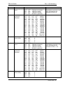
1
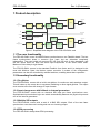
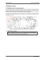
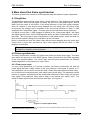
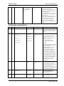
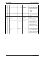
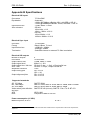
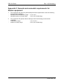
FRS-3G-DUAL Dual Frame Synchronizer for 3G/HD/SD-SDI User manual Rev. A (Preliminary) Nevion Nordre Kullerød 1 3241 Sandefjord Norway Tel: +47 33 48 99 99 nevion.com FRS-3G-DUAL Rev. A (Preliminary) Nevion Support Nevion Europe Nevion USA P.O. Box 1020 3204 Sandefjord, Norway Support phone 1: +47 33 48 99 97 Support phone 2: +47 90 60 99 99 1600 Emerson Avenue Oxnard, CA 93033, USA Toll free North America: (866) 515-0811 Outside North America: +1 (805) 247-8560 E-mail: [email protected] See http://www.nevion.com/support/ for service hours for customer support globally. Revision history Current revision of this document is the uppermost in the table below. Rev. Repl. Date Sign A - 20130829 TB Change description Initial version, preliminary nevion.com | 2 FRS-3G-DUAL Rev. A (Preliminary) Contents Revision history ........................................................................................................ 2 1 Product description ................................................................................................ 5 1.1 The core functionality .................................................................................................... 5 1.2 Secondary functionality ................................................................................................. 5 1.2.1 De-glitcher.................................................................................................................. 5 1.2.2 Input change-over with fallback to internal generators ................................................ 5 1.2.3 Multiple SDI outputs ................................................................................................... 5 1.2.4 EDH processing ......................................................................................................... 5 1.3 Product variants and how they differ ............................................................................. 6 2 How to get started ................................................................................................. 7 2.1 Power requirements ...................................................................................................... 7 2.2 Physical connections ..................................................................................................... 7 2.2.1 Sync input .................................................................................................................. 8 2.2.2 GPI outputs (alarms) .................................................................................................. 8 2.2.3 GPI inputs .................................................................................................................. 8 2.2.4 GPI pin-out ................................................................................................................. 8 2.3 What the LEDs mean .................................................................................................... 9 2.3.1 Exceptions/special conditions for the LEDS ............................................................... 9 2.4 Selecting between Gyda mode or Manual mode ........................................................... 9 2.5 A very brief guide to Manual mode set-up ..................................................................... 9 2.6 A very brief guide to Gyda mode set-up .......................................................................10 2.7 How to get back to factory defaults?.............................................................................11 3 Detailed control.................................................................................................... 12 3.1 Detailed control in manual mode ..................................................................................12 3.1.1 DIP switch functions ..................................................................................................12 3.1.2 Factory reset function ................................................................................................14 3.2 Detailed control in Gyda mode .....................................................................................16 3.2.1 Information page .......................................................................................................16 3.2.2 Configuration page ....................................................................................................17 3.2.3 Input selection ...........................................................................................................18 3.2.4 Video generator.........................................................................................................19 3.2.5 VS error triggered by … ............................................................................................20 3.2.6 Signal integrity...........................................................................................................20 3.2.7 Phase delay ..............................................................................................................20 3.2.8 Additional frames delay .............................................................................................20 4 More about the frame synchronizer ..................................................................... 22 4.1 De-glitcher....................................................................................................................22 4.2 Frame synchronizer .....................................................................................................22 4.2.1 Frame sync mode .....................................................................................................22 4.2.2 Frame delay mode ....................................................................................................24 Appendix A RS422 commands ............................................................................... 25 A.1 FLP4.0 required commands .........................................................................................25 A.2 Normal control blocks ..................................................................................................26 Appendix B Specifications ...................................................................................... 28 Appendix C General environmental requirements for Nevion equipment ............... 29 nevion.com | 3 FRS-3G-DUAL Rev. A (Preliminary) Appendix D Materials declaration and recycling information .................................. 30 D.1 Materials declaration....................................................................................................30 D.2 Recycling information ..................................................................................................30 Product Warranty.................................................................................................... 31 nevion.com | 4 FRS-3G-DUAL Rev. A (Preliminary) 1 Product description Video Generators SDI OUT 1 X-point SDI ELECTRICAL IN 1 REF Reclocker / De-serialiser 1 Deglitcher 1 SDI OUT 1 Video Fixed Delay 1 Frame Sync 1 Genlock STATUS GPI 4 X GPI Control General Ctrl GYDA Video Generators SDI OUT 2 X-point SDI ELECTRICAL IN 2 Reclocker / De-serialiser 2 Deglitcher 2 Frame Sync 2 SDI OUT 2 Video Fixed Delay 2 Figure 1: Simplified block diagram of the FRS-3G-DUAL card 1.1 The core functionality The FRS-3G-DUAL is two 3G-HDSDI frame synchronizers on one Flashlink board. The two frame synchronizers share a common sync input, but are otherwise completely independent. They can handle all common SD, HD, and 3G level A video standards, and the two inputs need not have the same input frequencies or the same frame rates. Maximum video delay is eight frames. The FRS-3G-DUAL comes in the standard Flashlink form factor and it is designed to be used with Multicon Gyda, the Nevion system controller. A subset of the configuration parameters can also be controlled by onboard switches, enabling stand-alone operation. 1.2 Secondary functionality 1.2.1 De-glitcher The FRS-3G-DUAL comes with a built-in de-glitcher for continuous and seamless output. This will clean up line errors due to up-stream switching or other signal glitches. The output even remains error-free with change of input formats. 1.2.2 Input change-over with fallback to internal generators The FRS-3G-DUAL comes with an electrical SDI input per frame synchronizer core. Sophisticated input selection logic can switch automatically between the physical input and one of the internal generators. 1.2.3 Multiple SDI outputs The FRS-3G-DUAL comes with a total of 4 BNC SDI outputs. Each of the two frame synchronizer cores has one inverting and one non-inverting output. 1.2.4 EDH processing The FRS-3G-DUAL always does EDH processing. nevion.com | 5 FRS-3G-DUAL Rev. A (Preliminary) 1.3 Product variants and how they differ There are no lower-spec variants of the FRS-3G-DUAL. For frame synchronizers that only accept SD-SDI and/or HD-SDI input, see the FRS-SDI, FRS-HD-DMUX, and FRS-HDXMUX4 product families. For prices, please contact Nevion or an authorized Nevion dealer. nevion.com | 6 FRS-3G-DUAL Rev. A (Preliminary) 2 How to get started 2.1 Power requirements The absolute maximum power consumption for this module is 8.1 W. This figure varies considerably with the combination of video standards used. If the module will always be used with the same combination of input standards, the table below can be used to determine the actual maximum power consumption, and to determine how many modules can safely be used in one frame. Note that the module will draw all its power from +5 V. Check the +5 V rating of the power supply, generally it will be lower than the rating for the entire supply. Table 1: Maximum power consumption as a function of video standards used Input/output standard SD HD 720p HD 1080i 3G 1080p 7.35 W 7.35 W 7.35 W 8.10 W 2.2 Physical connections Figure 2: FRS-3G-DUAL-C1 backplane. Connection side one the left, side towards the frame on the right The backplane for the FRS-3G-DUAL is labeled FRS-3G-DUAL-C1. It is designed to be fitted in a Flashlink rack unit and to take up a single slot. The connection side will face outward on the back side of the Flashlink rack when mounted correctly. The table below is an overview of the connectors and their associated functions. Function 3G/HD/SD-SDI input 3G/HD/SD-SDI output 1 3G/HD/SD-SDI output 1 inverted 3G/HD/SD-SDI input 2 3G/HD/SD-SDI output 2 3G/HD/SD-SDI output 2 inverted Label IN1 OUT1 _____ OUT1 IN2 OUT2 _____ Connector type BNC BNC BNC BNC BNC nevion.com | 7 FRS-3G-DUAL Rev. A (Preliminary) Black & Burst/ tri-level frequency reference input GPI out GPI in OUT2 SYNC BNC GPI/DATA TP45, pin 1, 2, 3 (pin 8 = GND) GPI/DATA TP45, pin 4, 5, 6, 7 (pin 8 = GND) Table 2: Connector functions Unused SDI inputs/outputs should be terminated with 75 Ohm. 2.2.1 Sync input The main module features a slide switch to select between sync taken from the backplane input (switch position marked “BP”) and a frame-distributed sync (switch position marked “RACK”). At the time of writing this manual no frame-distributed sync is available, and the switch should be kept in the “BP” position. The backplane also features a switch on the component side (the side facing into the frame). This is a switchable termination for the backplane sync input. By setting the slide switch in Figure 2 to the “ON” position, the sync input will be terminated to 75 Ohm. Generally, the sync inputs should be terminated if each sync input is fed from a separate output of a distribution amplifier. If one sync output is passively split and fed to several modules (T-connectors) one module should be terminated while the others should be left unterminated. If the module will be used without a frequency reference the positions of these slide switches do not matter. 2.2.2 GPI outputs (alarms) The FRS-3G-DUAL hardware module has three GPI output lines. The first one, GPIO 0, reflects the general status of the card, and thereby acts as an all-purpose alarm. GPIO 1 and GPOI 2 reflect the reclocker lock status of inputs 1 and 2, respectively. See Table 3 below for pin-out of the GPI lines. 2.2.3 GPI inputs The FRS-3G-DUAL hardware module has four GPI inputs. No functions have yet been assigned to these input lines. 2.2.4 GPI pin-out GPI name Function GPIO 0, General error status for the Status module. Will also activate at firmware loading, when the module is not processing video. GPIO 1 Not assigned GPIO 2 Not assigned GPI 0 GPI 1 GPI 2 GPI 3 Ground Not assigned Not assigned Not assigned Not assigned 0 volt pin Pin # Mode Pin 1 Inverted Open Collector (open is alarm) Direction Output Pin 2 Inverted Open Pin 3 Collector (open is alarm) Pin 4 Pin 5 TTL, 0V = Pin 6 active level Pin 7 Pin 8 0V. Output Output Input Input Input Input nevion.com | 8 FRS-3G-DUAL Rev. A (Preliminary) Table 3: The TP45 (8pin modular jack) in detail 2.3 What the LEDs mean Card status Red LED PTC fuse has been triggered or FPGA programming has failed IN1 Video signal absent. IN2 Video signal absent. Sync input status Sync signal absent Orange LED Module has not been programmed, or RESET and OVR DIPS are both on, or module is loading firmware. Video signal present but card unable to lock VCXO Video signal present but card unable to lock VCXO Sync signal present but card unable to lock all VCXO Green LED Module is OK No light Module has no power Video signal present and locked Module has not been programmed Video signal present and locked Module has not been programmed B&B or Tri-level sync in lock Module has not been programmed Table 4: LED states and what they mean 2.3.1 Exceptions/special conditions for the LEDS The locate command will make all four LEDs blink on and off synchronously to quickly identify the module in a larger installation. The condition of the card is not otherwise affected by the command, only the appearance of the LEDs will change. The LEDs return to their normal states and functions after the special locate condition has timed out. 2.4 Selecting between Gyda mode or Manual mode The board can be configured either manually or through the system controller Multicon GYDA. Since there’s a limited number of switches available compared to the total number of settings available for the module, only a subset of the parameters can be adjusted when operating in manual mode. Generally, the parameters that cannot be directly controlled by the DIP switches will take their settings from the previous Multicon GYDA session. This means that for a specific manual setup it may be necessary to configure the module with a Multicon GYDA before switching to manual mode. To reach manual mode, the lower DIP (labelled OVR) on the module must be switched to the “On” position (to the right) and the board must be re-booted. This isolates the board from Multicon GYDA control, but the module will still accept commands to retrieve its status, and also the commands necessary to initiate and perform firmware upgrades. 2.5 A very brief guide to Manual mode set-up More details and possibilities are described in chapter 3.1, entitled ‘Detailed control in manual mode’. This is just the bare minimum to get started and get a useful output in Manual mode: nevion.com | 9 FRS-3G-DUAL Rev. A (Preliminary) 2.6 A very brief guide to Gyda mode set-up All of these settings are covered in much more detail in chapter 3.2. These are just the most important settings to get started: Arguably the most important setting is where to take the input from. Since the module is only available with one single electrical BNC input per frame sync core, a good starting point would be to take the input from these BNCs: nevion.com | 10 FRS-3G-DUAL Rev. A (Preliminary) What this means is that the electrical input will be chosen whenever a signal is present, and if a signal is not present, the output will frame freeze for 500 ms before resorting to an internal fallback generator. Here this generator is set to produce Colourbar. 2.7 How to get back to factory defaults? To access the function that will reset the module and reload the factory default settings, the module must briefly be put into manual mode. The entire procedure is described in chapter 3.1.2. nevion.com | 11 FRS-3G-DUAL Rev. A (Preliminary) 3 Detailed control 3.1 Detailed control in manual mode To reach manual mode, the lower DIP (labelled OVR) on the module must be switched to the “On” position (to the right) and the board must be re-booted. This isolates the board from Multicon GYDA control, but the module will still accept commands to retrieve its status, and also commands related to initiate and perform firmware upgrades. The Manual Mode configuration controls are all found on the front side of the board. There are three sets of DIP switches, and the switches are numbered and labeled counterclockwise from 1 to 24. Figure 3: The figure shows a top view component printout of the board. 3.1.1 DIP switch functions The two horizontally mounted DIP switch packages are here denoted DIP1DIP16, counted from right to leftt. The vertically mounted DIP package is denoted with DIP17-DIP24, counted from top to bottom. nevion.com | 12 FRS-3G-DUAL Switch 1-2 Function name Frame sync 2 input 3-6 Frame sync 2 generator standard 7-8 Frame sync 2 frame delay 9-10 Frame sync 1 input 11-14 Frame sync 1 generator standard 15-16 Frame sync 1 frame delay Rev. A (Preliminary) Function DIPs DIP2 DIP1 OFF OFF Fallback to Colorbar OFF ON Fallback to Black ON OFF Fallback to Muted ON ON Module is generator DIP6 DIP5 DIP4 DIP3 VSTD OFF OFF OFF OFF 486/29i OFF OFF OFF ON 576/25i OFF OFF ON OFF 1080/24p OFF OFF ON ON 1080/25i OFF ON OFF OFF 1080/30i OFF ON OFF ON 1080/29i OFF ON ON OFF 1080/50p OFF ON ON ON 1080/60p ON OFF OFF OFF 1080/59p ON OFF OFF ON 720/24p ON OFF ON OFF 720/25p ON OFF ON ON 720/50p ON ON OFF OFF 720/60p ON ON OFF ON 720/59p ON ON ON OFF Reserved ON ON ON ON Reserved DIP8 DIP7 FRAMES OFF OFF 0 OFF ON 1 ON OFF 2 ON ON 3 DIP10 DIP9 OFF OFF Fallback to Colorbar OFF ON Fallback to Black ON OFF Fallback to Muted ON ON Module is generator DIP14 DIP13 DIP12 DIP11 VSTD OFF OFF OFF OFF 486/29i OFF OFF OFF ON 576/25i OFF OFF ON OFF 1080/24p OFF OFF ON ON 1080/25i OFF ON OFF OFF 1080/30i OFF ON OFF ON 1080/29i OFF ON ON OFF 1080/50p OFF ON ON ON 1080/60p ON OFF OFF OFF 1080/59p ON OFF OFF ON 720/24p ON OFF ON OFF 720/25p ON OFF ON ON 720/50p ON ON OFF OFF 720/60p ON ON OFF ON 720/59p ON ON ON OFF Reserved ON ON ON ON Reserved DIP8 DIP7 FRAMES OFF OFF 0 OFF ON 1 ON OFF 2 ON ON 3 Comment When the module is set as a standalone generator, the video standard can be selected on DIPs 3-6. When the module is set as a standalone generator, the video standard can be selected on DIPs 11-14. nevion.com | 13 FRS-3G-DUAL 17-19 Frame sync 1 phase delay 20-22 Frame sync 2 phase delay F-RESET F-RESET OVR OVR Rev. A (Preliminary) DIP22 DIP21 DIP20 LINES OFF OFF OFF -5 OFF OFF ON -4 OFF ON OFF -3 OFF ON ON -2 ON OFF OFF -1 ON OFF ON 0 ON ON OFF 1 ON ON ON 2 DIP19 DIP18 DIP17 LINES OFF OFF OFF -5 OFF OFF ON -4 OFF ON OFF -3 OFF ON ON -2 ON OFF OFF -1 ON OFF ON 0 ON ON OFF 1 ON ON ON 2 Off: Use values preset by MULTICON GYDA. On: RESET to factory defaults Off: MULTICON GYDA mode On: Manual mode This DIP is only read at power up. See chapter 3.1.2. This DIP is only read at power up. OVR is short term for MULTICON GYDA override Table 5: DIP SWITCH FUNCTIONS 3.1.2 Factory reset function The factory reset puts the card back to its initial state, as it was delivered from the factory. These settings are just a starting condition for the board, and new settings applied by the user will still take effect and be stored. If a Multicon GYDA is controlling the frame in which the factory reset operation is performed, Multicon will see the re-insertion of the card in step 4 below as a hot-swap event, and it will try to write the previously stored settings back to the card. There are two ways to avoid this mechanism: The safest and easiest way is to keep the Multicon GYDA pulled out during the factory reset procedure. The next best thing is to select the Manual mode in step 3, which will effectively prevent the card from acknowledging the commands sent from Multicon in step 4. After ~30 seconds the Multicon settings will instead have been updated from the card settings (some of which may now have been overridden by the DIP switches!), and then the card can be unplugged once more, and returned to Gyda mode. The factory reset is a four-step procedure: 1. Pull the main card out of the frame, and set the two DIPs labelled F-RESET and OVR to their On positions. 2. Re-insert the card into the frame. The Status LED will now be a permanent orange colour. No further waiting is needed after seeing the Status LED lit up orange. 3. Pull the card out of the frame again, and return the DIP F-RESET to its Off position, and set the OVR to the desired mode of operation. 4. Re-insert the card into the frame, and it should now boot as normal again. It is only at the end of this boot-up that the settings are actually reset, and to ensure that the new settings are stored properly it is important that the card is now kept powered for nevion.com | 14 FRS-3G-DUAL Rev. A (Preliminary) a few seconds after the Status LED has turned green. The card will start to operate as normal with the new settings right away. nevion.com | 15 FRS-3G-DUAL Rev. A (Preliminary) 3.2 Detailed control in Gyda mode All functions of the card can be controlled through the Multicon GYDA control system. The Multicon GYDA has an information page and a configuration page. 3.2.1 Information page Figure 4: Multicon GYDA information page The information page shows a dynamic block-diagram of the board and some additional informative text. The block diagram updates with the board status, showing input signal selected and signals missing (by red crosses over signal lines). nevion.com | 16 FRS-3G-DUAL Rev. A (Preliminary) The information text below the dynamic block diagram lists information not easily conveyed in a graphical manner. Sync source will indicate either Blackburst or Tri-level sync if a reference input has been detected, and Loss of lock if no reference has been detected. Electrical input (1/2) will indicate either Signal present or No signal. Signal present merely means that a carrier has been detected, actual video content may or may not be present. Reclocker (1/2) will indicate either Locked or Loss of lock. Lock means that the module has been able to recognize and lock to the video content. Input source (1/2) will indicate either Electrical, Generator, or Mute. This is an indication of current input selection. If Generator or Mute is shown, it will either be because the selector has been forced to this selection by the user, or because they have been set as fallback for the electrical input, which is currently not present. Signal integrity (1/2) is split in three sections. The first will indicate the present input video standard, and the second is an error counter that will count the number of frames with at least one countable error. The third section consists of the individual error bits as reported by the module. A red background color means that this error was detected, and counted. A green background color means that no error of this type was detected. A gray background color means that the user has decided to ignore this type of error. Phase delay (1/2) displays a recalculation of the phase delay set by the user. The user can set the delay in video lines and/or video samples. The combined setting will be recalculated into nanoseconds and video samples for the current video standard. This can be used as a tool to match up the delays with other types of equipment with different input formats for the phase delay. Additional video delay (1/2) is simply a reminder of the additional frame delay added by the user. This is usually used to add delay to match the processing time with that of other equipment. 3.2.2 Configuration page The configuration page is shown over the next two pages. The different configuration parameters are explained in detail in the following sub-chapters. The order in which the settings are presented follows the order in the graphical user interface. Since there are two independent - but identical - sets of controls (for the two independent frame synchronizers), only the first set will be covered. nevion.com | 17 FRS-3G-DUAL Rev. A (Preliminary) Figure 5 Multicon Gyda configuration page 3.2.3 Input selection Figure 6: Multicon GYDA view of generator selected as fallback for electrical input Each half of the FRS-3G-DUAL has one electrical input, in addition to a number of internal generators that conceptually can be thought of as alternative inputs. The input is selected by specifying two priorities, referred to as Main and Backup1. The module will always start by looking at the input selected as Main. This input will be selected as long as it is present. If the module is not able to lock to this input for Hold time, the module will go to the next priority, Backup1, if that exists. If ‘-‘ has been selected as Backup1, this means that no fallback exists, and the module will stay in Main forever, even if the Main signal disappears, and the output will be frozen until Main reappears. If the module is in Backup1 and the Main signal reappears, it will have to be continuously present for Lock time before the module will again select the Main source. This may look like a very complex to do the input selection, and in some ways that is correct. When there is only one physical input the number of useful combinations is rather small: nevion.com | 18 FRS-3G-DUAL Electrical → ‘-’ Rev. A (Preliminary) Video output will freeze for as long as the electrical input is missing. No fallback. If at any time the input is again locked for a duration of Lock time, the module will again un-freeze the picture. Electrical → Mute Video will freeze for Hold time after the electrical input disappears, then the output will be muted, i.e. the output drivers are turned off. If at any time the input is again locked for a duration of Lock time, the module will again select the electrical input and turn the output drivers back on. Electrical → Generator Video will freeze for Hold time after the electrical input disappears, then the output will switch to an internal generator. The generator pattern (Black or Color bar) is selected in the Video generator block, but the video format will always be the same as last seen by the module. If at any time the input is again locked for a duration of Lock time, the module will again switch from generator to the electrical input. Generator → ‘-‘ This forces the output to use one of the internal generators. Both the pattern (Black or Color bar) and the video format are selected in the Video generator block. Mute → ‘-‘ This forces the output to Mute, i.e. the output drivers are turned off. Combinations like Generator → Mute will be reduced to Generator → ‘-‘ in the reply from the module, because the internal generators are always present, and hence the Backup1 setting is irrelevant. Likewise Electrical → Electrical will be reduced to Electrical → ‘-‘ , because it doesn’t make sense to have an input as its own fallback. 3.2.4 Video generator Figure 7: Multicon GYDA view of video generator and the possible selections therein The video generator block work in conjunction with the input selector, and together they decide how the module behaves when the input signal is lost. See the previous chapter. Note that the Video format selection only comes into play when the module is used as a standalone generator. In normal operation the video format will be taken from the last legal input seen by the module. nevion.com | 19 FRS-3G-DUAL Rev. A (Preliminary) 3.2.5 VS error triggered by … Figure 8: Multicon Gyda view of the VS error bit functionality selector This must be seen in relation to both the Video generator block and the Signal integrity block (next chapter). In the Signal integrity block there’s an error bit called VS, i.e. Video Standard error. Normally this error bit would only be asserted when the internal flywheel of the reclocker is locked, but to an unknown video standard. When VSTD error is selected in Video error triggered by, the Video standard setting in the Video generator block will also act as an Expected video standard. Whenever the Expected video standard does not match the incoming video standard (as reported in the Signal integrity block, the VS error bit will be asserted. The VS error bit can then make the error counter in the Signal integrity block act as a video standard alarm. 3.2.6 Signal integrity Figure 9: Multicon Gyda view of the signal integrity block, all error bits set to count In this block a number of standard video error bits can be set to be either counted or ignored. The counter will count frames wit at least one error. Multiple errors in the same frame will only be counted once, but the actual errors as reported from the module can be seen on the module’s info page (see description in chapter 3.2.1). 3.2.7 Phase delay This is arguably the core of the frame synchronizer. By setting the Phase delay in video lines and video samples, the phase of the output can be adjusted relative to an incoming sync reference. Negative delays will force start-of-frame for the output to come slightly earlier than the reference (compensating for reference propagation time or precompensating for a cable length on the output). Of course, for negative phase delays approaching one frame, it may be more practical to imagine it as a smaller positive delay. For practical purposes one can consider the phase delay block to be a delay line that automatically adjusts itself between 0-1 frame to keep a constant phase between itself and the reference. If a reference signal is not available, the delay in lines and samples will simply be added to the frame delay in Additional video delay, and the two delays together will act as a single constant delay line. Figure 10: Multicon Gyda view of the delay settings 3.2.8 Additional frames delay As mentioned the phase delay will effectively be a 0-1 frame variable delay line when a reference is present. The Additional video delay setting will then add entire frames to this delay, and for practical purposes an additional delay of N frames is equivalent to saying that the phase delay will vary between N and (N+1) frames. The Additional delay setting is useful to compensate for processing delays in other equipment (notably Dolby E processors, if audio is split from video and embedded again at a later stage). Maximum nevion.com | 20 FRS-3G-DUAL Rev. A (Preliminary) frame delay is 7 frames, which means that maximum total delay is 7-8 frames with reference present. nevion.com | 21 FRS-3G-DUAL Rev. A (Preliminary) 4 More about the frame synchronizer The frame synchronizer consists of a few important parts that deserve further explanation: 4.1 De-glitcher The de-glitcher corrects timing errors within a single video line. The de-glitcher has a 2048 samples buffer. When the first signal is present, we call it the “initial phase signal”, data is taken from the centre of this buffer. If the timing reference of the video signal changes, when for instance a new source being switched into the signal path, the timing errors occurring by this change will be corrected if the new timing reference is within +/-1024 samples of the “initial phase signal”. This also goes for all consecutive timing references. If a signal is more than +/-1024 samples off relative to the “initial phase signal”, the output will repeat the last frame, refill the 2048 samples buffer and take out data from the centre of the buffer. This new signal is now considered the “initial phase signal”. Audio will fade out when a frame repeat is being done, and fade in at the new frame. Hence, it produces an error free video output without frame wrapping when the video input comes from a router with synchronous input video signals that all lies within +/-1024 samples of each other. The de-glitcher output is always seamless. When a signal is repeated the audio is faded out. It fades in at the new frame. 4.2 Frame synchronizer The frame synchronizer consists of a frame store buffer and some control logic. The frame store buffer can store up to 8 full 3GHD frames. Data is fetched from this buffer according to the user specified delays. The control logic sets the frame synchronizer into different modes dependent on the presence of a sync input. 4.2.1 Frame sync mode If a sync input (BlackBurst or Tri-level) is present, the frame synchronizer will have an output signal that has a delay relative to the sync reference. As covered in chapter 3.2.7, two parameters can be used to control this delay: Phase delay and Additional frame delay. Let us first focus on the phase delay, also called output phase delay. This parameter can be positive or negative, and determines the relationship between the video output and the sync input signal. This parameter really adds a delay on an internal sync signal, isync1. The output is always synchronous and in phase with isync, see Figure 11. Figure 11: Positive phase delay 1 Note that isync is not a physical entity, but a term used in this context to explain the delay process and the use of the configurable parameters related to this process. nevion.com | 22 FRS-3G-DUAL Rev. A (Preliminary) Figure 11 show how the sync signal and the isync signal would look on an oscilloscope, if converted to analogue signals. The delay of isync can be given in lines, and samples. The delay can be negative, see Figure 12. Figure 12: Negative phase delay It is not possible to specify a more negative phase delay than -1 frame, or more positive phase delay than +1 frame. Doing so would be pointless, as the distance between two start-of-frame pulses for the sync reference must by definition be 1 frame, and the delay will wrap around. A phase delay of 1 frame + N lines would be completely equivalent to a phase delay of just N lines. The same applies to a phase delay of -1 frame + (-N lines), it would be equivalent to just –N lines. Strictly speaking, it would suffice to allow the phase delay to be within the interval -1/2 frame to +1/2 frame (or just 0 frames to 1 frame, or even -1 frame to 0 frames); every possible phase delay could be specified this way. But people like to think of these things in different ways, and the phase delay can thus be specified in the entire interval -1 frame to +1 frame. In addition to the phase delay, the user may specify Additional frame delay. If the input signal doesn’t have the exact same frequency as the sync reference, the phase between the input and the reference will vary continuously, and hence the delay must also vary over time. When the Additional frame delay is set to N frames, the delay through the card will be somewhere between N and (N+1) frames, and vary over time unless the sync and SDI input have the same frequency. Here’s what happens when an external error event occurs: If video input disappears Given that a stable sync input exists: If the SDI input disappears, the output picture will freeze for Hold time and then go to one of the internal video generators (depending on the module’s configuration). If video input reappears Given stable sync input, the video will reappear after the module has had stable lock to the video input for a duration of Lock time. If sync input disappears Given that stable SDI input exists: If the sync signal disappears, the card will revert to frame delay mode, see Chapter 4.2.2. NOTE: This will result in a frame roll as the delay changes. If sync input reappears nevion.com | 23 FRS-3G-DUAL Rev. A (Preliminary) Given that a stable SDI input exists: If the sync reference reappears the delay logic will change back to frame sync mode. Hence the internal clock will be locked to the sync signal and the delay will change again. NOTE: This will result in a frame roll as the delay changes. If both signals disappears The picture will first freeze for Hold time and then go to one of the internal video generators (depending on the module’s configuration). The output is now referenced to the local clock source. This clock will however be kept within 1 ppm of the last sync source seen by the module. 4.2.2 Frame delay mode In this mode a sync signal is not present. The phase delay will be set relative to the SDIinput. In effect this will create a delay line with length equal to the sum of the phase delay and the additional frame delay, and the output frequency will be locked to the input frequence. Here’s what happens when an external error event occurs: If video signal disappears The picture will first freeze for Hold time and then go to one of the internal video generators (depending on the module’s configuration). The output is now referenced to the local clock source. This clock will however be kept within 1 ppm of the last video input seen by the module. If video signal reappears If the input video signal reappears, the video will reappear on the output Lock time after the input has stabilized. The delay will be set to the same as before input was lost. NOTE: This may cause a frame roll. If a sync input appears Given that a stable SDI input exists: If a sync signal appears the delay mode will change to frame sync mode, see Chapter 4.2.1. Hence the internal clock will be locked to the sync signal and the delay will change. NOTE: This will result in a frame roll as the delay changes. nevion.com | 24 FRS-3G-DUAL Rev. A (Preliminary) Appendix A RS422 commands A.1 FLP4.0 required commands Block Blk# Commands Example Response Control - - ? ? product name\ SW rev n.m\ FW rev r.s\ protocol ver 4.0\ Hello command. Note 1: No other commands will be available until the card has received this hello. Note 2: This command will also enable checksums. Note 3: Cards are designed to be hot-swappable. To sync with the start of a new command, the cards will wait for a <lf> character before looking for a valid command. conf 0 - conf 0 *too long to list* Configuration settings Retrieves the card's configurable settings. Each addressable block is represented by a single line. Dynamic status may be included in response, but is usually reported in info only. - - info info *too long to list* Dynamic status info Blocks with static settings only will usually not be included, see conf above. - - chk off chk off ok Checksum off If issued twice in succession, this command will disable checksums. Note: Responses will still have the checksums appended. NOTE1: ? command turns the checksum back on - - locate on <seconds> locate on 3 ok Card locator This command will cause all the LEDs to flash for a user specified number of seconds. If omitted, the value <seconds> will be set to a default of 120 seconds. The flashing can be terminated at any time with locate off. Card address This command will check and update the card's current rack and slot address, which is normally only done at start-up. locate off locate off - - address address address <address> - - filename filename frs3gdual-0123.ffw filename frs3gdual-0112.mfw <name>'.'<extension> Firmware upgrades The <name> part must match the card's hardware and include a revision number, and the extension must be either 'ffw' for FPGA firmware or 'mfw' for microcontroller firmware. - - fin fin ok Finalize Finalize the programming of the microcontroller. See description of the uC bootloader (separate document). nevion.com | 25 FRS-3G-DUAL misc 0 Rev. A (Preliminary) - NOT AVAILABLE BY COMMAND. ONLY FOUND in Conf 0 prog | fin ' ' | ovr Misc info prog if the card is freshly programmed by the bootloader and the program is still un-finalized. fin is the normal condition. ovr if DIP-switch 16 is set to the ON position and the card is under DIPswitch control. Note 1: The info part of misc has additional functionality when locate is used: locating <remaining seconds>. This enables a visible countdown clock in Multicon GYDA, but is not a required part of FLP400. A.2 Normal control blocks Block Blk# Commands Example ceq 0-1 - ceq 1 cho 0-1 pri <k> | pri <k> <l> | pri <k> <l> <m> cho 0 pri 0 cho 1 pri 0 1 latch reset t1 <hold_time> t2 <lock_time> Response cd | ncd Control Cable equalizer for electrical input. No control; only used to report carrier detect or no carrier detect. size 4 pri k,l,m t1 Video input select <hold time> t2 <lock time> pri: a prioritized list of inputs, cho 0 latch reset used when change-over is automatic. The list can have 1 or cho 0 t1 1000 2 entries, or levels. 0 = from electrical input cho 0 t2 1000 1 = internal video generator 2 = mute 3 = none The module will always respond with 2 levels, filling in 3=none for the levels not used. t1 and t2: change-over doesn't happen immediately, as a precaution against glitches and unstable signals. The timers t1 and t2 let the user decide how long (in ms) we will cling on to a missing input before we consider it gone and move on to the next pri level, and how long an input with a higher priority should be present before we consider it repaired and switch back, respectively. dly 0-1 <lines>lines <samples>sps dly 1 1lines 30sps 'phase' <lines> lines <samples> sps Video phase Sets the output phase relative to the sync reference. If lines != 0 the resulting phase will vary with incoming video standard. In info this block reports back the current delay in nanoseconds and converted to samples only. dly 2-3 <frames>frms dly 0 2frms 'tgt' <frames> frms Additional frame delay This sets the additional video delay of the card. gpi 0-1 act | inact gpi 1 act gpi 1 inact VS error triggered by inact: Flywheel error only act: VS error bit also set if nevion.com | 26 FRS-3G-DUAL Rev. A (Preliminary) incoming vstd doesn’t match vgen vstd. pwr 0-3 - pwr 0 <nom_voltage>Vnom Power monitoring <voltage>V The nominal voltages are listet with the measured voltages. For this product the following voltages are measured: 0: 1.2Vnom 1: 1.2Vnom 2: 1.2Vnom 3: 5.0Vnom rcl 0-1 - rcl 0 lock | lol Reclocker No control, only used to report lock status. sync 0 - sync 0 'lol' | ('lock' ('trilvl' | 'bb' | 'sdi') ) Frequency reference for video output. Status only, no commands available. vgen 0-1 cbar | black vgen 0 cbar video <lns>/<rate><scan> vgen 0 video 1080/24p video <lns>/<rate><scan> (cbar | black ) Internal video generator. The video generator will be activated in two different ways: If selected as a fallback option the generator will generate the selected pattern when the other input(s) are missing, and then use the video settings from the last external source present. It can also be selected as the main input in cho 0-1, in which case its own video settings will also be used. msk <16b_mask> vmon 0 msk 0xFFF msk <12b_mask> Video monitoring. Error counting. The count itself is reported in info. Errors can be masked off and not counted; this is the purpose of the mask. The counter itself is 12b and will wrap around, but can also be reset by issuing reset. vmon 0-1 reset vmon 0 reset nevion.com | 27 FRS-3G-DUAL Rev. A (Preliminary) Appendix B Specifications Electrical SDI inputs Connectors Equalization Input Return loss Jitter tolerance 75 Ohm BNC Automatic; >300m @270Mbps w/Belden 8281, with BER < 10E-12 >100m @1485Mbps w/Belden 1694A, with BER < 10E-12 >15dB, 5MHz -1.5GHz SD limit: 10Hz-1kHz: >1 UI 10kHz – 5MHz: >0.2 UI HD limit: 10Hz-100kHz: >1 UI 100kHz–10MHz: >0.2 UI Electrical Sync input Connector Format Input Return loss Termination 75 Ohm BNC Black & Burst, Tri-level >35dB @ < 10MHz, 30dB @ < 30MHz Selectable internal or external 75 Ohm termination Electrical SDI outputs Number of outputs Connectors Output Return loss Output signal level Output signal rise / fall time 20% - 80% Amplitude overshoot Output timing jitter Output alignment jitter 4 75 Ohm BNC >15dB, 5MHz -1.5GHz 800mV +/- 10% SD limit: [0.4ns – 1.5ns]; <0.5ns rise/fall var. HD limit: < 270ps, <100ps rise/fall var. <10% SD: <0.2 UI HD: <1 UI SD: <0.15 UI HD: <0.15 UI Supported standards SD, 270 Mbps HD, 1485 Mbps 3G, 2970 Mbps Video switch point definition and sync AES EDH SMPTE 259M SMPTE 274M, SMPTE 291M, SMPTE 292M, SMPTE 296M SMPTE 291M, SMPTE 424M, SMPTE 425M SMPTE RP168 (tri-level), SMPTE 170m, ITU-R. BT.470 AES3-1996 Compliant to SMPTE-RP165 Power consumption (+5 VDC) Maximum power, at 50°C 8.1 W 2 2 Actual power consumption varies with the video standards used. Please see the complete table under Power requirements, chapter 2.1. nevion.com | 28 FRS-3G-DUAL Rev. A (Preliminary) Appendix C General environmental requirements for Nevion equipment 1. 2. - The equipment will meet the guaranteed performance specification under the following environmental conditions: Operating room temperature range: 0°C to 45°C Operating relative humidity range: <90% (non-condensing) The equipment will operate without damage under the following environmental conditions: Temperature range: -10°C to 55°C Relative humidity range: <95% (non-condensing) nevion.com | 29 FRS-3G-DUAL Rev. A (Preliminary) Appendix D Materials declaration and recycling information D.1 Materials declaration For product sold into China after 1st March 2007, we comply with the “Administrative Measure on the Control of Pollution by Electronic Information Products”. In the first stage of this legislation, content of six hazardous materials has to be declared. The table below shows the required information. Toxic or hazardous substances and elements 組成名稱 Part Name FRS-3G-DUAL 鉛 汞 镉 六价铬 多溴联苯 Lead Mercury Cadmium Hexavalent Polybrominated (Pb) (Hg) (Cd) Chromium biphenyls (Cr(VI)) (PBB) O O O O O 多溴二苯醚 Polybrominated diphenyl ethers (PBDE) O O: Indicates that this toxic or hazardous substance contained in all of the homogeneous materials for this part is below the limit requirement in SJ/T11363-2006. X: Indicates that this toxic or hazardous substance contained in at least one of the homogeneous materials used for this part is above the limit requirement in SJ/T11363-2006. This is indicated by the product marking: D.2 Recycling information Nevion provides assistance to customers and recyclers through our web site http://www.nevion.com/. Please contact Nevion’s Customer Support for assistance with recycling if this site does not show the information you require. Where it is not possible to return the product to Nevion or its agents for recycling, the following general information may be of assistance: Before attempting disassembly, ensure the product is completely disconnected from power and signal connections. All major parts are marked or labeled to show their material content. Depending on the date of manufacture, this product may contain lead in solder. Some circuit boards may contain battery-backed memory devices. nevion.com | 30 FRS-3G-DUAL Rev. A (Preliminary) Product Warranty The warranty terms and conditions for the product(s) covered by this manual follow the General Sales Conditions by Nevion, which are available on the company web site: www.nevion.com nevion.com | 31