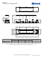
1
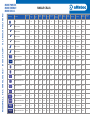
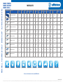
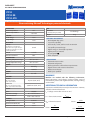
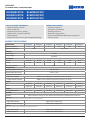
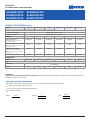
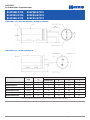
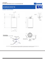
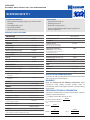
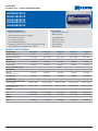
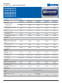
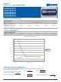
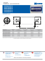
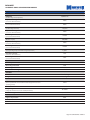
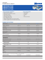
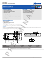
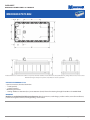
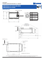
Boostcap Ultracapacitors by alfatec GmbH & Co. KG Meckenloher Str. 11 D-91126 Rednitzhembach Telefon: 0 91 22 / 97 96-0 Telefax: 0 91 22 / 97 96-50 Web: www.alfatec.de Email: [email protected] M A X W E L L T E C H N O LO G I E S ® B O O S T C A P ® U LT R A C A PA C I T O R S MORE POWER. MORE ENERGY. MORE IDEAS. Product Image SINGLE CELLS ™ Capacitance (F) Rated Voltage (V) Surge Voltage (V) ESR, DC (mohm) ESR 1kHz (mohm) lc (mA) Max. current (A), 1 sec Max. continuous current (A) Weight (kg) PC10 10 2.5 2.7 180 130 0.04 19 2.5 0.0063 BCAP0005 P270 5 2.7 2.85 200 110 0.015 3.4 1.6 BCAP0010 P270 10 2.7 2.85 80 60 0.03 7.5 BCAP0025 P270 25 2.7 2.85 42 30 0.045 BCAP0050 P270 50 2.7 2.85 20 15 BCAP0100 P270 100 2.7 2.85 15 BCAP0150 P270 150 2.7 2.85 BCAP0310 P270 T08 310 2.7 BCAP0350 E270 T09 350 BCAP0650 P270 K04 Pmax (W/kg) Balancing Terminal Thermal Monitoring Protection Level 2.5 1,900 N/A Lead N/A - 0.0022 2.2 7,500 N/A Lead N/A - 3.5 0.004 2.3 7,550 N/A Lead N/A - 16.5 5 0.007 3.62 8,678 N/A Radial lead N/A - 0.075 33.7 7.1 0.014 3.62 8,678 N/A Radial lead N/A - 9 0.26 54 0.025 4.05 8,100 N/A Snap In N/A - 14 8 0.5 65.3 9.1 0.035 4.34 6,509 N/A Snap in N/A - 2.85 2.2 1.1 0.45 240 30 0.062 5.06 26,700 N/A Radial N/A - 2.7 2.85 3.2 1.6 0.3 220 25 0.063 5.62 18,300 N/A Radial N/A - 650 2.7 2.8 0.8 0.6 1.5 585 105 0.16 3.29 15,100 N/A Threaded N/A - BCAP0650 P270 K05 / K06 650 2.7 2.8 0.8 0.6 1.5 585 105 0.16 3.29 15,100 N/A Weldable N/A - BCAP1200 P270 K04 1200 2.7 2.8 0.58 0.44 2.7 975 110 0.26 4.05 13,800 N/A Threaded N/A - BCAP1200 P270 K05 / K06 1200 2.7 2.8 0.58 0.44 2.7 975 110 0.26 4.05 13,800 N/A Weldable N/A - BCAP1500 P270 K04 1500 2.7 2.8 0.47 0.35 3.0 1,210 115 0.28 4.75 16,200 N/A Threaded N/A - BCAP1500 P270 K05 / K06 1500 2.7 2.8 0.47 0.35 3.0 1,210 115 0.28 4.75 16,200 N/A Weldable N/A - BCAP2000 P270 K04 2000 2.7 2.8 0.35 0.26 4.2 1,620 125 0.36 5.06 17,500 N/A Threaded N/A - BCAP2000 P270 K05 / K06 2000 2.7 2.8 0.35 0.26 4.2 1,620 125 0.36 5.06 17,500 N/A Weldable N/A - BCAP3000 P270 K04 3000 2.7 2.8 0.29 0.24 5.2 2,215 150 0.51 5.52 13,800 N/A Threaded N/A - BCAP3000 P270 K05 / K06 3000 2.7 2.8 0.29 0.24 5.2 2,215 150 0.51 5.52 13,800 N/A Weldable N/A - Product Name 8.2 Emax (Wh/kg) M AX W E L L T E C H N O LO G I E S ® B O O S TC A P ® U LT R AC A PAC I TO R S MORE POWER. MORE ENERGY. MORE IDEAS. Product Image Product Name BMOD0058 E016 B02 MODULES Capacitance (F) 58 Rated Voltage (V) Surge Voltage (V) 16.2 16.2 ™ ESR, DC (mohm) ESR 1kHz (mohm) 22 10 50 lc (mA) Max. continuous current (A) Weight (kg) Emax (Wh/kg) Pmax (W/kg) Balancing Terminal Thermal Monitoring Protection Level 200 20 0.55 2.67 8,200 Passive Screw N/A - 6,000 VMS Screw Y IP65 Max. current (A), 1 sec BMOD0110 P016 110 16.2 16.8 5.4 4 1.5 - 30 2.7 1.49 BMOD0250 P016 250 16.2 16.8 4.1 3.3 3 2,000 115 4.45 2.05 4,400 VMS Screw Y IP65 BMOD0500 P016 B01 500 16.2 16.8 2.4 1.7 5.2 4,000 150 5.75 3.17 6,700 VMS Screw Y IP65 BMOD0500 P016 B02 500 16.2 16.8 2.4 1.7 150 4,000 150 5.75 3.17 6,700 Passive Screw Y IP65 BMOD0083 P048 80 48.6 50.4 12.3 9.8 3 1,080 115 11 2.48 5,400 VMS Screw Y IP65 BMOD0110 P048 110 48.6 50.4 8.1. 5.2 4.2 1410 125 12 3,01 8,800 VMS Screw Y BMOD0165 P048 165 48.6 50.4 7.1 5.2 5.21 1,850 150 14.2 3.8 7,900 VMS Screw Y IP65 BMOD0094 P075 94 75 90 12.5 N/A 5.2 750 50 25 3.98 6,800 Passive Screw Y IP54 SAEJ2380 BMOD0063 P125 63 125 130 18 14.0 5.2 750 150 58 2.53 5,200 VMS Radsok* Y IP65 IP65 For more information visit: www.alfatec.de Stand: Okt. 2009 This flyer is printed on paper with 15% recycled content . VMS: Voltage Management System • *Radsok® is a trademark of Amphenol • The information in this document is correct at time of printing. For the latest information and product updates please visit www.maxwell.com. Images not to scale. DATASHEET ® PC SERIES ULTRACAPACITORS PC10 PC10-90 PC10-270 PRODUCT SPECIFICATIONS Now containing Maxwell Technologies patented electrode SIZE CAPACITANCE Nominal capacitance 10 F Tolerance capacitance -10/+20% VOLTAGE Rated voltage 2.5 V Surge voltage 2.7 V RESISTANCE ESR, DC Specification is as-built value. Value after test is higher. Lifespan and Cycles specifications are from as-built specification. ESR, AC Resistance tolerance 0.18 Ω 130 mΩ Max. Dimensions (L x W x H) (mm) (±0.5mm) See drawings. 6.3g Weight FEATURES AND BENEFITS • Over 500,000 duty cycles • 10 year life capability • Hermetically sealed, stainless steel construction • Low profile prismatic design • Higher energy vs. electrolytic capacitors • Higher power vs. batteries • UL recognized • RoHS compliant TEMPERATURE Operating temperature range -40°C to +70°C Storage temperature range -40°C to +85°C POWER Pd 660 W/kg Pv 1390 W/L ENERGY Emax 6.9 mAh LIFESPAN Lifetime ∆C < 20% decrease ESR < 100% increase Endurance ∆C < 20% decrease from rated ESR < 100% increase from rated 10 years (2.5V, 25°C) 3,000 hours (2.5V, 70°C) Capacitance change Internal resistance MARKINGS Modules are marked with the following information: Rated capacitance, rated voltage, product number, name of manufacturer, positive and negative terminal, warning marking, serial number. ADDITIONAL TECHNICAL INFORMATION Capacitance and ESR, DC measured per document no. 1007239, available at www.maxwell.com. CYCLES Cycles APPLICATIONS • Automatic meter readers • Automatic subsystems • Back up power for soft shut down requirements • Digital cameras and consumer electronics • Wireless transmissions • NASA space qualified 500,000 ∆C < 20% decrease ESR < 100% increase lc = leakage current after 72 hours at 25°C lsc = short circuit current = CURRENT Leakage current 0.04 mA Short circuit current (lsc) 19 A Maximum continuous current 2.5 A 07 October 2009 Rth = thermal resistance Pmax = V2 4R (1khz) mass V Rated ESR DC Emax = ½ CV2 3,600 x mass Pd = 0.12V2 R (DC) mass Page 1 • Document number: 1003996.11 DATASHEET ® PC SERIES ULTRACAPACITORS PC10 PC10-90 PC10-270 DIMENSIONS (mm) PC10 PC10-270 PC10-90 8 min. 6 min. + Ø d ± .05 L ± .5 L + 3.5 max Body + Shrink W ± 0.3 T ± 0.2 p ± .5 3.1 ± .5 Part Description Vol (l) Dimensions in millimeters L W T d p Package qty. PC10 0.003 29.6 23.6 4.8 0.5 5.1 1920 PC10-90 0.003 35.9 23.6 4.8 0.5 5.1 1824 0.003 35.9 23.6 4.8 0.5 5.1 1824 PC10-270 Product dimensions are for reference only unless otherwise identified. Product dimensions and specifications may change without notice. Please contact Maxwell Technologies directly for any technical specifications critical to application. MOUNTING RECOMMENDATIONS All leads are tinned from 1.5mm of capacitor body. It is recommended that parts stay within protective packaging until ready to use. Parts may be soldered or wave soldered. Request supplemental information related to mounting instructions if necessary. Components should not be operated outside recommended limits. 07 October 2009 Page 2 • Document number: 1003996.11 DATASHEET ® HC POWER SERIES ULTRACAPACITORS BCAP0005 P270 BCAP0010 P270 BCAP0025 P270 BCAP0050 P270 BCAP0100 P270 BCAP0150 P270 TYPICAL FEATURES AND BENEFITS • Ultra-low internal resistance • Two pin radial lead • Resistant against reverse polarity • 500,000 cycles, 10 year life capability • RoHS compliant • Proprietary material science and packaging technology EXAMPLE APPLICATIONS • Consumer electronics • Industrial and automation • Portable power tools • Renewable energy systems • Short term UPS (uninterruptible power supply) and telecom systems PRODUCT SPECIFICATIONS CAPACITANCE Nominal capacitance BCAP0005 BCAP0010 BCAP0025 BCAP0050 BCAP0100 BCAP0150 5F 10 F 25 F 50 F 100 F 150 F ±20% Capacitance tolerance -0% / +20% VOLTAGE Rated voltage 2.7 V DC Surge voltage 2.85 V DC RESISTANCE ESR, DC 200 mΩ 80 mΩ 42 mΩ 20 mΩ 15 mΩ 14 mΩ ESR, AC 110 mΩ 60 mΩ 30 mΩ 15 mΩ 9 mΩ 8 mΩ Max. Resistance tolerance TEMPERATURE Operating temperature range -40°C to +65°C Storage temperature range -40°C to +70°C Temperature characteristics Capacitance change Within ± 5% of initial measured value at 25°C ( at -40°C) Internal resistance change Within ± 50% of initial measured value at 25°C ( at -40°C) POWER Pd 1,980 W/kg 2,730 W/kg 2,900 W/kg 3,100 W/kg 2,400 W/kg 1,700 W/kg Pmax 7,500 W/kg 7,550 W/kg 8,600 W/kg 8,600 W/kg 8,100 W/kg 6,500 W/kg 2.3 Wh/kg 2.53 Wh/kg 3.62 Wh/kg 3.62 Wh/kg 4.05 Wh/kg 4.34 Wh/kg ENERGY Energy density (Emax) LIFESPAN Shelf life After 1,000 hours storage at 65°C without load shall meet specification for endurance Endurance After 1,000 hours application of rated voltage at 65°C. Within % of initial specified value. Capacitance change Within 30% of initial value Internal resistance change Within 40% of initial value Life test After 10 years at rated voltage and 25°C. Within % of initial specified value. Capacitance change Within 30% of initial value Internal resistance Within 100% of initial value Page 1 • Document number: 1013793.3 DATASHEET ® HC POWER SERIES ULTRACAPACITORS BCAP0005 P270 BCAP0010 P270 BCAP0025 P270 BCAP0050 P270 BCAP0100 P270 BCAP0150 P270 PRODUCT SPECIFICATIONS (cont.) CYCLES BCAP0005 BCAP0010 BCAP0025 BCAP0050 BCAP0100 BCAP0150 Capacitors cycled between specified voltage and half rated voltage under constant current at 25°C (500,000 cycles). Capacitance change Within 30% of initial value Internal resistance Within 100% of initial value CURRENT 0.015 mA 0.03 mA 0.045 mA 0.075 mA 0.26 mA 0.5 mA Maximum continuous current 1.6 A 3.5 A 4.9 A 7.1 A 8.2 A 9.1 A Maximum peak current 3.4 A 7.5 A 16.5 A 33.7 A 54.0 A 65.3 A Short circuit current (Isc) 13.5 A 33.8 A 64.3 A 135.0 A 180.0 A 193.0 A Radial lead Radial lead Radial lead Radial lead Snap in Snap in 25.0g 35.0g Leakage current (Ic) After 72 hours at 25°C. Initial leakage current can be higher. Assuming 15°C temperature rise above ambient temperature. Maximum peak current calculations: IMAX = nominal capacitance x 0.5 (rated voltage) / 1 sec. CONNECTION Terminal SIZE See drawings Dimensions Weight 2.2g 4.0g 7.0g 14.0g MARKINGS Modules are marked with the following information: Rated capacitance, rated voltage, product number, name of manufacturer, negative terminal, serial number. ADDITIONAL TECHNICAL INFORMATION Capacitance and ESR, DC measured per document no. 1007239, available at www.maxwell.com. lc = leakage current after 72 hours at 25°C lsc = short circuit current (maximum peak current) Rth = thermal resistance ½ CV2 Emax = 3,600 x mass V2 Pmax = 4R (1khz) mass Pd = 0.12V2 R (DC) mass Page 2 • Document number: 1013793.3 DATASHEET ® HC POWER SERIES ULTRACAPACITORS BCAP0005 P270 BCAP0010 P270 BCAP0025 P270 BCAP0050 P270 BCAP0100 P270 BCAP0150 P270 DIMENSIONS (mm) - BCAP0005, BCAP0010, BCAP0025, BCAP0050 d f D L DIMENSIONS (mm) - BCAP0100, BCAP0150 L Part Description Vol (0xL) Mass (g) BCAP0005 P270 10 x 20 BCAP0010 P270 Size (mm) L (+2mm max) D d f 2.2 20 10 0.6 5.3 10 x 30 4 30 10 0.6 5.3 BCAP0025 P270 T01 16 x 26 7 26 16 0.8 7.5 BCAP0050 P270 T01 18 x 41 14 41 18 0.8 7.5 BCAP0100 P270 T01 22 x 45 25 45 22 1.5 10 BCAP0150 P270 T01 25 x 50 35 50 25 1.5 10 Product dimensions are for reference only unless otherwise identified. Product dimensions and specifications may change without notice. Please contact Maxwell Technologies directly for any technical specifications critical to application. Page 3 • Document number: 1013793.3 DATASHEET ® BC POWER SERIES RADIAL D CELL 310F ULTRACAPACITOR BCAP0310 P270 T10 FEATURES AND BENEFITS • Round, radial mounting design for easy surface mount assembly • Over 500,000 duty cycles • 10 year life capability • Ultra-low internal resistance APPLICATIONS • Automotive subsystems • Industrial power back up • Portable power tools • Renewable energy systems PRODUCT SPECIFICATIONS CAPACITANCE CURRENT Nominal capacitance 310 F Capacitance tolerance +20% / -0% VOLTAGE Leakage current 0.45 mA Short circuit current (lsc) 1,220 A After 72 hours at 25°C. Initial leakage current can be higher. Rated voltage 2.7 V DC Surge voltage 2.85 V DC CAUTION: Current possible with short circuit from UR. Do not use as an operating current. N/A Maximum continuous current 30 A Maximum peak current, 1 sec 240 A Isolation voltage RESISTANCE ESR, DC Resistance tolerance Thermal resistance (Rth) 2.2mΩ Max. 10.9°C/W TEMPERATURE CONNECTION SIZE -40°C to +65°C Volume Storage temperature range -40°C to +70°C Mass Temperature characteristics Internal resistance ± 5% of value at 25°C ± 150% of value at 25°C POWER Pd 6,400 W/kg ENERGY Emax See drawing Dimensions Operating temperature range Capacitance change Radial Terminal 5.06 Wh/kg LIFESPAN Endurance After 1,000 hours application of rated voltage at 65°C. 0.053 L 62g MOUNTING RECOMMENDATIONS Solder tabs to PCB. See application note for further information and slot spacing recommendations. For proper mounting, the use of a holder or spacer between the cell and the PCB is required. MARKINGS Parts are marked with the following information: Rated capacitance, rated voltage, product number, name of manufacturer, positive and negative terminal, warning marking, serial number. ADDITIONAL TECHNICAL INFORMATION Capacitance change <20% decrease Internal resistance <25% increase Capacitance and ESR, DC measured per document no. 1007239, available at www.maxwell.com. Capacitance change ≤20% decrease Internal resistance ≤100% increase lc = leakage current after 72 hours at 25°C VRATED lsc (short circuit current) = ESR Rth = thermal resistance Life test After 10 years at rated voltage and 25°C. CYCLES Cycles - Capacitors cycles between specified voltage and half rated voltage under constant current at 25°C (500,000 cycles) Capacitance change ≤20% decrease Internal resistance ≤100% increase Emax = ½ CV2 3,600 x mass Pmax = V2 4R (1khz) mass Pd = 0.12V2 R (DC) mass Page 1 • Document number: 1014625.1 DATASHEET ® BC POWER SERIES RADIAL D CELL 310F ULTRACAPACITOR BCAP0310 P270 T10 PRODUCT SPECIFICATIONS Positive Negative Product dimensions are for reference only unless otherwise identified. Product dimensions and specifications may change without notice. Please contact Maxwell Technologies directly for any technical specifications critical to application. Page 2 • Document number: 1014625.1 DATASHEET ® BC ENERGY SERIES RADIAL D CELL 350F ULTRACAPACITOR BCAP0350 E270 T11 FEATURES AND BENEFITS • Round, radial mounting design for easy surface mount assembly • Over 500,000 duty cycles • 10 year life capability • Ultra-low internal resistance APPLICATIONS • Industrial power back up • Portable power tools • Renewable energy systems • Short term UPS (uninterruptible power supply) and telecom applications PRODUCT SPECIFICATIONS CAPACITANCE Capacitance change 20% decrease Nominal capacitance 350 F Internal resistance 100% increase Capacitance tolerance +20% / -0% VOLTAGE CURRENT Leakage current 0.3 mA Short circuit current (lsc) 840 A RESISTANCE Maximum continuous current 25 A ESR, DC Maximum peak current, 1 sec 220 A Rated voltage 2.7 V DC Surge voltage 2.85 V DC Maximum operating voltage 2.7 V DC Isolation voltage Resistance tolerance Thermal resistance (Rth) N/A 3.2mΩ Max. 10.9C/W After 72 hours at 25°C. Initial leakage current can be higher. CAUTION: Current possible with short circuit from UR. Do not use as an operating current. CONNECTION Radial Terminal SIZE TEMPERATURE Operating temperature range -40°C to +65°C Dimensions Storage temperature range -40°C to +70°C Volume Internal resistance % at 25°C ± 5% ± 150% 4,300 W/kg ENERGY Emax 5.62 Wh/kg MOUNTING RECOMMENDATIONS Solder tabs to PCB. See application note for further information and slot spacing recommendations. Parts are marked with the following information: Rated capacitance, rated voltage, product number, name of manufacturer, positive and negative terminal, warning marking, serial number. ADDITIONAL TECHNICAL INFORMATION LIFESPAN Endurance After 1,000 hours application of rated voltage at 65°C. Capacitance change <20% decrease Internal resistance <25% increase Life test At rated voltage and 25°C. 10 years Capacitance change ≤20% decrease Internal resistance ≤100% increase Capacitance and ESR, DC measured per document no. 1007239, available at www.maxwell.com. lc = leakage current after 72 hours at 25°C VRATED lsc (short circuit current) = ESR Rth = thermal resistance Emax = ½ CV2 3,600 x mass Pmax = V2 4R (1khz) mass CYCLES Cycles - Capacitors cycles between specified voltage and half rated voltage under constant current at 25°C (500,000 cycles) 63g MARKINGS POWER Pd 0.053 L Mass Temperature characteristics Capacitance change % at 25°C See drawing Pd = 0.12V2 R (DC) mass Page 1 • Document number: 1014624.2 DATASHEET ® BC ENERGY SERIES RADIAL D CELL 350F ULTRACAPACITOR BCAP0350 E270 T11 PRODUCT SPECIFICATIONS 1 2 3 4 5 7 6 1.5 A Limit of Tin (Sn) Plating Area 7.1 E 4.9 7.7 3 DETAIL E SCALE 2 : 1 61 68.7 B F C +0.3 33 - 0.2 45° + Safety vent location E Negative Positive D data matrix code 16x16 (4x4mm) VIEW F Board drillings Board thickness : 1.6 mm 2.5 E 2. 5 7 12 3.5 10 10 2.5 CQ 1 TEB 1 SBE 1 EPM 1 General tolerances ISO 2768 mK, EN ISO 13920 Modif. Date Object Rad F Material Weight [Kg] Disposal to third persons or reproduction even in part, GiL 31.07.09 Design Product/ dimensions are for reference only unless otherwise identified. Product dimensions Drawn and specifications may change without notice. 61 g prohibited without writen authority from the compagny. © All rights Reserved Maxwell technologies - Depart. DATE Please contact Maxwell Technologies directly for any technical specifications critical to application. Approuv. QSE 2 3 4 xx.xx.xx SolidWorks / Checked 1 Visa EPM DeM Drawing ref. BCAP0350 E270 T 15.07.09 All dimensions in [mm] Echelle: Page 2 • Document number: 1014624.2 1:1 DATASHEET ® K2 SERIES 650 F - 3,000 F ULTRACAPACITORS BCAP0650 P270 BCAP1200 P270 BCAP1500 P270 BCAP2000 P270 BCAP3000 P270 FEATURES AND BENEFITS • Ultra-low internal resistance • Highest power performance available • Lowest RC time constant • 2.7 V operating voltage • Over 1,000,000 duty cycles • Proprietary material science and packaging technology • Threaded terminal or weldable post versions APPLICATIONS • Automotive subsystems • Back-up power • Grid stabilization • Hybrid drive trains • Rail system power • Transportation • Utility vehicles PRODUCT SPECIFICATIONS BCAP0650 BCAP1200 BCAP1500 BCAP2000 BCAP3000 Nominal capacitance 650 F 1,200 F 1,500 F 2,000 F 3,000 F Tolerance capacitance -0% / +20% -0% / +20% -0% / +20% -0% / +20% -0% / +20% Rated voltage 2.7 V DC 2.7 V DC 2.7 V DC 2.7 V DC 2.7 V DC Surge voltage 2.85 V DC 2.85 V DC 2.85 V DC 2.85 V DC 2.85 V DC CAPACITANCE VOLTAGE N/A Maximum operating voltage RESISTANCE ESR, DC Max., room temperature 0.8 mΩ 0.58 mΩ 0.47 mΩ 0.35 mΩ 0.29 mΩ ESR, 1khz (Max.) 0.6 mΩ 0.44 mΩ 0.35 mΩ 0.26 mΩ 0.24 mΩ Operating temperature range -40°C to +65°C -40°C to +65°C -40°C to +65°C -40°C to +65°C -40°C to +65°C Storage temperature range -40°C to +70°C -40°C to +70°C -40°C to +70°C -40°C to +70°C -40°C to +70°C Pd 6,800 W/kg 5,800 W/kg 6,600 W/kg 6,900 W/kg 5,900 W/kg Pmax 18,900 W/kg 15,900 W/kg 18,500 W/kg 19,400 W/kg 14,800 W/kg 4.11 Wh/kg 4.67 Wh/kg 5.42 Wh/kg 5.63 Wh/kg 5.96 Wh/kg TEMPERATURE Stored uncharged Cell case temperature POWER ENERGY Emax Page 1 • Document number: 1015370.1 DATASHEET ® K2 SERIES 650 F - 3,000 F ULTRACAPACITORS BCAP0650 P270 BCAP1200 P270 BCAP1500 P270 BCAP2000 P270 BCAP3000 P270 PRODUCT SPECIFICATIONS (cont.) DC LIFESPAN BCAP0650 BCAP1200 BCAP1500 BCAP2000 BCAP3000 Endurance 1,500 hours 1,500 hours 1,500 hours 1,500 hours 1,500 hours Capacitance change % of rated value ≤20% ≤20% ≤20% ≤20% ≤20% Internal resistance change % of rated value ≤60% ≤60% ≤60% ≤60% ≤60% 10 years 10 years 10 years 10 years 10 years ≤20% ≤20% ≤20% ≤20% ≤20% ≤100% ≤100% ≤100% ≤100% ≤100% 1 million 1 million 1 million 1 million 1 million ≤20% ≤20% ≤20% ≤20% ≤20% ≤100% ≤100% ≤100% ≤100% ≤100% 2 years 2 years 2 years 2 years 2 years Capacitance change % of rated value 10% decrease 10% decrease 10% decrease 10% decrease 10% decrease ESR change % of rated value 50% increase 50% increase 50% increase 50% increase 50% increase Maximum continuous current 62 A 81 A 97 A 123 A 147 A Maximum peak current, 1 sec 575 A 955 A 1,185 A 1,585 A 2,165 A 1.5 mA 2.7 mA 3.0 mA 4.2 mA 5.2 mA 0.36kg 0.51kg At rated voltage and 65°C. Life test At rated voltage and 25°C. Capacitance change % of rated value Internal resistance change % of rated value CYCLE LIFE Cycles Between specified voltage and half rated voltage under constant current at 25°C. Capacitance change % of rated value Internal resistance change % of rated value SHELF LIFE Shelf Life Uncharged over storage temperature CURRENT Leakage current, ILC After 72 hours. Initial leakage current can be higher. CONNECTION Threaded or Weldable Terminal SIZE See drawings Dimensions (L x W x H) (mm) Weight 0.16kg 0.26kg 0.28kg Page 2 • Document number: 1015370.1 DATASHEET ® K2 SERIES 650 F - 3,000 F ULTRACAPACITORS BCAP0650 P270 BCAP1200 P270 BCAP1500 P270 BCAP2000 P270 BCAP3000 P270 PRODUCT SPECIFICATIONS (cont.) RATINGS AND SAFETY For all: ISO 16750, SAE J2380 Vibration resistance Short circuit current (lsc) CAUTION: Current possible with short circuit from rated voltage Do not use as an operating current. 3,350 A 4,650 A 5,700 A 7,700 A 9,300 A 6.5°C/W 5.3°C/W 4.5°C/W 3.8°C/W 3.2°C/W TYPICAL CHARACTERISTICS THERMAL CHARACTERISTICS Thermal resistance (Rth) Capacitance and ESR vs. Temperature 180% 170% 160% 150% Change from 25C Value 140% Capacitance DC ESR 130% 120% 110% 100% 90% 80% -60 -40 -20 0 20 40 60 80 Temperature (C) ADDITIONAL TECHNICAL INFORMATION Capacitance and ESR, DC measured per document no. 1007239, available at www.maxwell.com. V2 Unless specified, all specifications are at 25°C ½ CV2 Emax = 4R (1khz) Pmax = 3,600 x mass lc = leakage current after 72 hours at 25°C mass VRATED lsc (short circuit current) = 2 0.12V ESR ½V Rth = thermal resistance Maximum Peak Current (1 sec) = R (DC) Pd = ESR(DC) + 1 mass C Page 3 • Document number: 1015370.1 DATASHEET ® K2 SERIES 650 F - 3,000 F ULTRACAPACITORS BCAP0650 P270 BCAP1200 P270 BCAP1500 P270 BCAP2000 P270 BCAP3000 P270 MOUNTING RECOMMENDATIONS Do not reverse polarity. Maximum torque for M12 screw terminals is 14Nm. Cells are designed to be connected into series or parallel strings. Clean terminals before mounting. MARKINGS Capacitors - Rated capacitance and2rated voltage as well as energy/ 1power type 4 are marked with the following information 3 indication in the product naming. Serial number, name of manufacturer, positive and negative terminal, warning marking. REVISIONS REV CO DESCRIPTION 1 - PROTOTYPE D D DIMENSIONS D2 M12 X 1.75-6g M12 X 1.75-6g D1 C B A C 022.9 14 0.5 14 0.5 L Part Number Volume L (±0.3mm) D1 (±0.2mm) D2 (±0.7mm) BCAP0650 P270 K04 02 0.211 L 51.5 mm (±0.5mm) 60.4mm 60.7mm BCAP1200 P270 K04 02 0.294 L 74 mm 60.4mm 60.7mm BCAP1500 P270 K04 02 0.325 L 85 mm 60.4mm 60.7mm BCAP2000 P270 K04 02 0.373 L 102 mm 60.4mm 60.7mm BCAP3000 P270 K04 02 0.475 L 60.4mm 60.7mm 138 mm NOTICE: THE INFORMATION CONTAINED IN THIS DOCUMENT IS MAXWELL CONFIDENTIAL INFORMATION AND IS THE SOLE PROPERTY OF MAXWELL TECHNOLOGIES. ANY REPRODUCTION IN PART OR WHOLE WITHOUT WRITTEN PERMISSION OF MAXWELL TECHNOLOGIES IS PROHIBITED. MODEL BCAP0650 BCAP1200 BCAP1500 BCAP2000 BCAP3000 P/N 108351B 108384B 108385B 108386B 108387B 4 DO NOT SCALE DRAWING UNLESS OTHERWISE SPECIFIED, ALL DIMENSIONS ARE IN MILLIMETERS AFTER PLATING. DRAWN BREAK EDGES 0.3 LATHE FINISH 63 µINCH, MILL FINISH 125 µINCH X.XXX DIAMETERS 0.125 TIR X.XXX DIA SURFACES X/X .X .XX A 51.5 74 85 102 138 MATERIAL & ±.5 ±.25 ±.125 APPROVALS DATE 7/31/2009 R.DUBINSKAYA PER IFS CHECKED 0.025mm ANGLE ±0.5° B DESIGN ENGR 9244 BALBOA AVENUE, SAN DIEGO, CA 92123 U.S.A MECHANICAL ENGR A DESCRIPTION BCAP, ENVELOPE ASSY, K2, T PROCESS ENGR 3RD ANGLE PROJECTION TEST ENGR SIZE CAUTION CONTAINS PARTS AND/OR ASSEMBLIES SUSCEPTIBLE TO DAMAGE BY ELECTROSTATIC DISCHARGE (ESD) 3 FINISH QUALITY ENGR PRODUCTION ENGR 2 PER IFS CAGE CODE B 68911 SCALE 2:1 DOC. NO. PART NO. SEE TABLE REV 1014496 1 SHEET 1 OF 1 1 V A 7/01 Product dimensions are for reference only unless otherwise identified. Product dimensions and specifications may change without notice. Please contact Maxwell Technologies directly for any technical specifications critical to application. Page 4 • Document number: 1015370.1 REV X1 DATASHEET ® K2 SERIES 650 F - 3,000 F ULTRACAPACITORS BCAP0650 P270 BCAP1200 P270 4 BCAP1500 P270 BCAP2000 P270 BCAP3000 P270 D 3 2 1 REVISIONS REV CO DESCRIPTION 1 3811 PROTOTYPE CHANGE DIM FROM 3.20 TO 3.180+/-0.125 2 DIMENSIONS (cont.) C D2 14 ±0.05 D3 D1 022.9 3.180 0.125 3.180 0.125 L Volume Part Number BCAP0650 P270 K05 02 MODEL BCAP0650 BCAP1200 BCAP1500 BCAP2000 BCAP3000 A 1 P/N 108294B 108316B 108324B 108325B 108058B L (±0.3mm) 0.15 L BCAP1200 P270 K05 02 0.233 L BCAP1500 P270 K05 02 0.264 L BCAP2000 P270 K05 02 0.312 L BCAP3000 P270 K05 02 0.414 L D1 (±0.2mm) 51.5 mm (±0.5mm) A 51.5 74 85 102 138 74 mm NOTICE: THE INFORMATION CONTAINED IN THIS DOCUMENT IS MAXWELL CONFIDENTIAL INFORMATION AND IS THE SOLE PROPERTY OF MAXWELL TECHNOLOGIES. ANY REPRODUCTION IN PART OR WHOLE WITHOUT WRITTEN PERMISSION OF MAXWELL TECHNOLOGIES IS PROHIBITED. 85 mm 102 mm 138 mm 3RD ANGLE PROJECTION REFERENCE IFS FOR APPROVAL AND APPROVAL DATES D2 (±0.7mm) D3 (±0.05mm) 60.7mm 14mm 60.7mm 14mm 60.4mm DO NOT SCALE DRAWING 60.4mm UNLESS OTHERWISE SPECIFIED ALL DIMENSIONS ARE IN MILIMETERS AFTER PLATING. 60.4mm BREAK SHARP EDGES USE MINIMUM BEND RADII 60.4mm .X ±.5 .XX ±.25 .XXX ±.125 MATERIAL ANGLE ±0.5° 60.4mm Material APPROVALS DATE DRAWN 7/31/2009 Author 60.7mm CHECKED DESIGN ENGR MECHANICAL ENGR PROCESS ENGR TEST ENGR 1 60.7mm 14mm 9244 BALBOA AVENUE, SAN DIEGO, CA 92123 U.S.A ASSY, K2, J 60.7mm BCAP, ENVELOPE 14mm CAGE CODE SIZE CAUTION CONTAINS PARTS AND/OR ASSEMBLIES SUSCEPTIBLE TO DAMAGE BY ELECTROSTATIC DISCHARGE (ESD) FINISH QUALITY ENGR ANODIZE, TYPE II CLASS 2, PANTONE 286 BLUE 14mm DESCRIPTION B 68911 PART NO. SEE TABLE 1 OF 1 1014428 contact 1:1 notice. Please Product dimensions are for reference only unless otherwise identified. Product dimensions and specifications may 1change without 2 Maxwell Technologies directly for any technical specifications critical to application. 4 3 PRODUCTION ENGR 2 SCALE REV DOC. NO. SHEET 1 7/01 Maxwell Technologies, Inc. Worldwide Headquarters 9244 Balboa Avenue San Diego, CA 92123 USA Tel: +1 858 503 3300 US Free Call: +1 877 511 4324 Fax: +1 858 503 3301 Maxwell Technologies SA CH-1728 Rossens Switzerland Tel: +41 (0)26 411 85 00 Fax: +41 (0)26 411 85 05 Maxwell Technologies, GmbH Brucker Strasse 21 D-82205 Gilching Germany T: +49 (0)8105 24 16 10 F: +49 (0)8105 24 16 19 Online: www.maxwell.com • Email: [email protected] Maxwell Technologies, Inc. Shanghai Representative Office #13, CR Times Square 500 Zhangyang Road, Pudong Shanghai 200122, P.R. China Tel: +86 21 5836 5733 Fax: +86 21 5836 5620 Page 5 • Document number: 1015370.1 REV N/A DATASHEET ® 16V ENERGY SERIES ULTRACAPACITOR MODULES BMOD0058 E016 B02 FEATURES AND BENEFITS • • • • • 16 V DC working voltage Individually balanced cells Compact, lightweight system Screw terminals RoHS compliant TYPICAL APPLICATIONS • • • • • Automotive subsystems Consumer electronics Portable power tools Renewable energy systems Short term UPS and telecom PRODUCT SPECIFICATIONS ELECTRICAL Capacitance Nominal capacitance 58 F Tolerance capacitance - 0% / +20% Voltage Rated voltage 16 V DC Resistance ESR, DC 22 mΩ ESR, AC 10 mΩ (max., room temperature) (max., room temperature, 1kHz) Current Maximum continuous current 20 A Maximum peak current, 1 sec. 204 A Leakage current 50 mA (After 72 hours at 25°C. Initial leakage current can be higher.) TEMPERATURE Operating temperature range -40oC to +65oC Storage temperature range -40oC to + 70oC (Cell case temperature) (Stored uncharged) POWER AND ENERGY Usable power density, Pd Usable power 2,220 W/kg 1,400 W Impedance match power density, Pmax 4,600 W/kg Gravimetric energy density, Emax 3.3 Wh/kg Energy available 2.1 Wh Page 1 • Document number: 1015371.3 DATASHEET ® 16V ENERGY SERIES ULTRACAPACITOR MODULES DC LIFESPAN Endurance (at rated voltage and temperature) 2,000 hours Capacitance change ≤20% ESR change ≤60% (% decrease from rated value) (% increase from rated value) Life Test (at rated voltage and 20°C) 10 years Capacitance change ≤20% ESR change ≤100% (% decrease from rated value) (% increase from rated value) Cycle Test (Number of cycles) 500,000 Capacitance change ≤20% ESR change ≤100% (% decrease from rated value) (% increase from rated value) Shelf Life (Storage uncharged up to maximum storage temperature) 2 years Capacitance change 10% ESR change 50% (% decrease from rated value) (% increase from rated value) CONNECTION Power output terminals Monitoring and control Cell management Maximum series voltage M5 Screw N/A Passive 640 V DC PHYSICAL Dimensions Weight See drawing 0.63 kg SAFETY Short circuit current (Current possible with short circuit from rated voltage. Do not use as an operating current.) 727 A Certifications RoHS Surge voltage 16.8 V DC Isolation voltage 2,500 V DC (voltage above this level can cause catastrophic failure) ENVIRONMENTAL RATINGS Degrees of protection Vibration resistance Shock resistance IP54 IEC 60068-2-6 IEC 60068-2-27, -29 Page 2 • Document number: 1015371.3 DATASHEET ® 16V ENERGY SERIES ULTRACAPACITOR MODULES TYPICAL CHARACTERISTRICS THERMAL CHARACTERISTICS 180% Capacitance DC ESR Percentage change from value at 25°C 170% 160% 150% 140% 130% 120% 110% 100% 90% 80% -60 -40 -20 0 20 40 60 80 Temperature (°C) ADDITIONAL TECHNICAL INFORMATION Capacitance and ESR, DC measured per document no. 1007239 available at www.maxwell.com. Unless specified, all specifications are at 25°C. Short circuit current (lsc) = VRATED ESR(DC) Emax = ½ CV2 3,600 x mass Pmax = V2 4 x ESR(DC) x mass Pd = 0.12V2 ESR(DC) x mass Maximum peak current (1 sec) = ½ CV C x ESR(DC) + 1 MOUNTING RECOMMENDATIONS Do not reverse polarity. Mount with M4 screws, 40mm minimum length. Modules are designed to be connected into series or parallel strings. Clean terminals before mounting. MARKINGS Products are marked with the following information: Rated capacitance, rated voltage, product number, name of manufacturer, positive and negative terminal, warning marking, serial number. Page 3 • Document number: 1015371.3 DATASHEET 5 16V ENERGY SERIES ULTRACAPACITOR MODULES 6 7 8 ® DIMENSIONS 31 36 4.5 76 12.2 66.4 54.8 44.3 66.4 34 49.5 38.8 226.5 Part Description Dimensions (mm) BMOD0058 E016 B02 L (±0.5mm) W (±0.5mm) H (±0.5mm) 226.5 49.5 76.0 Package Quantity 10 Product dimensions are for reference only unless otherwise identified. Product dimensions and specifications may change without notice. Please contact Maxwell Technologies directly for any technical specifications critical to application. For internal use only; Not for customers CQ 1 TEB 1 SBE 1 EPM 1 Modif. Date 01 02 03 General tolerances ISO 2768 mK, EN ISO 13920 Object Online: www.maxwell.com • Email: [email protected] Rte de Monten CH-1728 Rosse Switzerland Page 4 • Document number: 1015371.3 BMOD0058 DATASHEET K2 BMOD POWER SERIES 16 V MODULES ® BMOD0110 P016 B01 BMOD0250 P016 B01 BMOD0500 P016 B01 BMOD0500 P016 B02 FEATURES AND BENEFITS • Ultra-low internal resistance • Highest power performance available • Lowest time constant • 16.2 V operating voltage • Over 1,000,000 duty cycles • Individually balanced cells • Voltage and temperature sensor output included • Compact, rugged, fully enclosed splash proof design APPLICATIONS • Transportation • Automotive • Industrial • Uninterruptible Power Supplies (UPS) • Telecommunication PRODUCT SPECIFICATIONS CAPACITANCE Nominal capacitance BMOD0110 BMOD0250 BMOD0500 B01 BMOD0500 B02 110 F 250 F 500 F 500 F 2.4 mΩ 2.4 mΩ 0.5°C/W 0.5°C/W +20% Tolerance capacitance VOLTAGE Rated voltage 16.2 V DC Surge voltage 16.8 V DC Maximum operating voltage 750 V DC Isolation voltage1 2,500 V AC RESISTANCE ESR, DC2 5.4 mΩ 4.1 mΩ Max. Resistance tolerance Thermal resistance (Rth) 1.1°C/W 0.91°C/W TEMPERATURE Operating temperature range -40°C to +65°C Storage temperature range -40°C to +70°C Temperature characteristics ± 5% at 25°C (at -40°C) Capacitance change ± 150% at 25°C (at -40°C) Internal resistance change POWER Pd 2,300 W/kg 1,700 W/kg 2,700 W/kg 2,300 W/kg Pmax 6,000 W/kg 4,400 W/kg 6,700 W/kg 6,700 W/kg 1.49 Wh/kg 2.05 Wh/kg 3.17 Wh/kg 3.17 Wh/kg ENERGY Emax LIFESPAN Endurance After 1,500 hours application of rated voltage at 65°C. Within % of initial specified value. Capacitance change <20% decrease Internal resistance change <60% increase Shelf life After 1,500 hours storage at 65°C without load shall meet specification for endurance. Page 1 • Document number: 1009363.6 DATASHEET K2 BMOD POWER SERIES 16 V MODULES ® BMOD0110 P016 B01 BMOD0250 P016 B01 BMOD0500 P016 B01 BMOD0500 P016 B02 Life test After 10 years at rated voltage and 25°C. Within % of initial specified value. Capacitance change 30% decrease Internal resistance 150% increase CYCLES Cycle test Capacitors cycled between specified voltage and half rated voltage under constant current at 25°C (1,000,000). Capacitance change 30% decrease Internal resistance 150% increase Within % of initial specified value. Within % of initial specified value. CURRENT Leakage current BMOD0110 3 Short circuit current (lsc) 4 Maximum continuous current BMOD0250 BMOD0500 B01 BMOD0500 B02 1.5 mA 3.0 mA 5.2 mA 150 mA 3,500 A 3,900 A 4,800 A 4,800 A 30 A 115 A 150 A 150 A 2,000 A 4,000 A 4,000 A VMS Passive 5.75 kg 5.75 kg SAE J2380 SAE J2380 Maximum peak current, 1 sec CONNECTION Screw Terminal MONITORING (IN-BUILT) Balancing5 VMS VMS NTC Thermal monitoring SIZE See drawings Dimensions (L x W x H) (mm) (±0.5mm) Weight 2.7 kg 4.45 kg RATINGS IP65 Humidity resistance Vibration resistance N/A SAE J2380 1 50Hz, 1 min. Maximum string operating voltage 1,500 V DC. Max., room temperature. 3 After 72 hours at 25°C. Initial leakage current can be higher. 4 CAUTION: C urrent possible with short circuit from UR. Do not use as an operating current. 5 VMS = Maxwell Technologies Voltage Management System. 2 MOUNTING RECOMMENDATIONS BMOD0110 modules can be secured at 4 locations at provided holes for M6 bolts. Follow user manual instructions for terminal, balance and output connections. BMOD0250 and BMOD0500 modules can be secured at 8 locations, 4 front face and/or 4 bottom face, at provided holes for M6 bolts. Follow user manual instructions for terminal, balance and output connections. MARKINGS Modules are marked with the following information: Rated capacitance, rated voltage, product number, name of manufacturer, positive and negative terminal, warning marking, serial number. Page 2 • Document number: 1009363.6 DATASHEET K2 BMOD POWER SERIES 16 V MODULES ® BMOD0110 P016 B01 BMOD0250 P016 B01 BMOD0500 P016 B01 BMOD0500 P016 B02 DIMENSIONS (mm) Part number L (±0.25mm) W (±0.25mm) H (±0.5mm) s (±0.5mm) 260.1 154.9 79.3 240.0 L (±0.25mm) W (±0.25mm) H (±0.5mm) s (±0.5mm) BMOD0250 P016 B01 416.2 67.2 103.2 53.7 BMOD0500 P016 B01 416.2 67.2 156.7 89.3 BMOD0500 P016 B02 416.2 67.2 156.7 89.3 BMOD0110 P016 B01 Part number Product dimensions are for reference only unless otherwise identified. Product dimensions and specifications may change without notice. Please contact Maxwell Technologies directly for any technical specifications critical to application. Page 3 • Document number: 1009363.6 DATASHEET ® K2 POWER SERIES 48 V MODULES BMOD0083 P048 BMOD0110 P048 BMOD0165 P048 TYPICAL FEATURES AND BENEFITS • Ultra-low internal resistance • Highest power performance available • Lowest time constant • 48.6 V operating voltage • Individually balanced cells • Over 1,000,000 duty cycles • Voltage and temperature sensor output included • Compact, rugged, fully enclosed splash-proof design TYPICAL APPLICATIONS • Transportation • Automotive • Industrial • UPS • Telecommunication PRODUCT SPECIFICATIONS CAPACITANCE BMOD0083 BMOD0110 BMOD0165 Nominal capacitance 80 F 110 F 165 F Tolerance capacitance +20% / -5% +20% / -5% +20% / -5% Rated voltage 48.6 V DC 48.6 V DC 48.6 V DC Surge voltage 50.4 V DC 50.4 V DC 50.4 V DC Maximum operating voltage 750 V DC 750 V DC 750 V DC 2,500 V DC 2,500 V DC 2,500 V DC 12.3 mΩ 8.1 mΩ 7.1 mΩ VOLTAGE Isolation voltage RESISTANCE ESR, DC Max., room temperature Resistance tolerance Max. Max. Max. 0.39°C/W 0.30°C/W 0.25v Operating temperature range -40°C to +65°C -40°C to +65°C -40°C to +65°C Storage temperature range -40°C to +70°C -40°C to +70°C -40°C to +70°C ± 5% ± 5% ± 5% ± 150% ± 150% ± 150% Thermal resistance (Rth) TEMPERATURE Temperature characteristics Capacitance change % at 25º C (at -40°C) Internal resistance change % at 25º C (at -40°C) POWER Pd 2,000 W/kg 2,900 W/kg 3,200 W/kg Pmax 5,400 W/kg 8,800 W/kg 7,900 W/kg 2.48 Wh/kg 3.01 Wh/kg 3.81 Wh/kg ENERGY Emax LIFESPAN Endurance After 1,500 hours application of rated voltage at 65°C. Within % of initial specified value. Capacitance change <20% decrease <20% decrease <20% decrease Internal resistance change <60% increase <60% increase <60% increase Page 1 • Document number: 1009365.7 DATASHEET ® K2 POWER SERIES 48 V MODULES BMOD0083 P048 BMOD0110 P048 BMOD0165 P048 PRODUCT SPECIFICATIONS (cont.) BMOD0083 BMOD0110 BMOD0165 10 years 10 years 10 years 30% decrease 30% decrease 30% decrease 150% increase 150% increase 150% increase Life test At rated voltage and 25°C. Capacitance change % of rated value Internal resistance % of rated value Shelf Life After 1,500 hours storage at 65°C without load shall meet specification for endurance. LIFE CYCLE Cycles 1,000,000 1,000,000 1,000,000 Capacitance change 30% decrease 30% decrease 30% decrease Internal resistance 150% increase 150% increase 150% increase 3 mA 4.2mA 5.2 mA 4,700 A 6,000 A 6,900 A 115 A 125 A 150 A 1,080 A 1,410 A 1,850 A + M8 x1.25/ - M10 x1.5 + M8 x1.25/ - M10 x1.5 + M8 x1.25/ - M10 x1.5 VMS (Voltage Management System) VMS (Voltage Management System) VMS (Voltage Management System) Fan voltage N/A N/A N/A Thermal monitoring NTC NTC NTC See drawing See drawing See drawing Volume 8.5 L 9.7 L 12.6 L Weight 11 kg 12 kg 14.2 kg IP65 IP65 IP65 SAE J2380 SAE J2380 SAE J2380 Between specified voltage and half rated voltage under constant current at 25°C. CURRENT Leakage current After 72 hours at 25°C. Initial leakage current can be higher. Short circuit current (lsc) CAUTION: C urrent possible with short circuit from UR. Do not use as an operating current. Maximum continuous current Maximum peak current, 1 sec 1 second, 10% duty cycle CONNECTION Terminal MONITORING Balancing SIZE Dimensions RATINGS Environmental resistance Vibration resistance ADDITIONAL TECHNICAL INFORMATION Capacitance and ESR, DC measured per document no. 1007239, available at www.maxwell.com. lc = leakage current after 72 hours at 25°C VRATED lsc (short circuit current) = ESR DC Rth = thermal resistance Pd = Pmax = 0.12V2 R (DC) mass Emax = ½ CV2 3,600 x mass V2 4R (1khz) mass Page 2 • Document number: 1009365.7 DATASHEET ® K2 POWER SERIES 48 V MODULES BMOD0083 P048 BMOD0110 P048 BMOD0165 P048 H H2 S DIMENSIONS (mm) Part number L (±0.25mm) W (±0.25mm) H (±0.25mm) H2 (±0.25mm) s (±0.5mm) BMOD0083 P048 416.2 190.2 103.2 126 53.7 BMOD0110 P048 416.2 190.2 120.2 143 70.7 BMOD0165 P048 416.2 190.2 156.7 180 89.3 Product dimensions are for reference only unless otherwise identified. Product dimensions and specifications may change without notice. Please contact Maxwell Technologies directly for any technical specifications critical to application. MOUNTING RECOMMENDATIONS Modules can be secured at 8 locations, 4 front face and/or 4 bottom face, at provided holes for M8 bolt. Follow user manual instructions for terminal, balance and output connections. MARKINGS Modules are marked with the following information: Rated capacitance, rated voltage, product number, name of manufacturer, positive and negative terminal, warning marking, serial number. Page 3 • Document number: 1009365.7 DATASHEET ® Y BMOD POWER SERIES 75 V MODULE BMOD0020 P075 PRODUCT SPECIFICATIONS CAPACITANCE 150 A CONNECTION Nominal capacitance 20 F Tolerance capacitance +20% / -0% Terminal Screw MONITORING (IN-BUILT) VOLTAGE Rated voltage 75 V DC Surge voltage 90 V DC Maximum operating voltage 86 V DC 2,500 V AC Isolation voltage RESISTANCE TEMPERATURE Operating temperature range -40°C to +65°C Storage temperature range -40°C to +70°C Temperature characteristics1 PT100 Dimensions (L x W x H) (mm) (±0.5mm) Weight 762 x 425 x 265 TBD RATINGS Humidity resistance IP54 Vibration resistance SAE J2380 ± 150% at 25º C IM POWER Thermal monitoring ± 5% at 25º C Capacitance change Internal resistance change Passive IN Max. Resistance tolerance Balancing SIZE 25.6 mΩ ESR, DC TBD Pd TBD Pmax ENERGY TBD Emax Energy available LIFESPAN Endurance2 11.7 Wh 150,000 hours EL Lifetime 75 V DC, RT7 Capacitance change 20% decrease Internal resistance change 60% increase Life AR Maximum peak current, 1 sec test3 Capacitance change 20% decrease Internal resistance 100% increase CYCLES PR Cycles 75 V to 37.5 V DC, RT7 Capacitance Internal change4 resistance4 1,000,000 30% decrease 150% increase 1 2 CURRENT Leakage current5 150 mA 3 Short circuit current (lsc) 6 4,800 A 5 Maximum continuous current 50 A 4 6 7 Within ± #% of initial measured value at #°C. After 1,500 hours application of rated voltage at 65°C. Within % of initial specified value. After 10 years at rated voltage and 25°C. Within % of initial specified value. Within % of initial specified value. After 72 hours at 25°C. Initial leakage current can be higher. CAUTION: C urrent possible with short circuit from UR. Do not use as an operating current. End of life charazterized as -20°C from nominal C, or increase of 100% in ESR. Page 1 • Document number: #######.# Y BMOD0020 P075 APPLICATIONS • Grid / Power Quality • UPS / Backup for Heavy Machinery • Wind Turbine Pitch Systems AR FEATURES AND BENEFITS • Ultra-low internal resistance • Highest power performance available • Lowest time constant • 75 V operating voltage • Temperature monitoring • Over 1,000,000 duty cycles • Water, dust and vibration resistance with IP54 and SAEJ 2380 compliance • Passive balancing IN INCLUDED IN BMOD0020 P075 2 Power connectors: • 1x M8 (positive), 1x M10 (negative) • Threaded aluminum 1 Monitoring connector • Harting® HAN 09 37 003 0801 (base), 09 36 008 3001(insert) • Thermal monitoring through PT100 Minco S17624PDYT20B MARKINGS Modules are marked with the following information: Rated capacitance, rated voltage, product number, name of manufacturer, positive serial number. and negative terminal, warning marking, IM Mass BMOD0020 P270 B02 515mm L (±1.0mm) TBD W (±1.0mm) H (±1.0mm) 263mm 211mm Page 2 • Document number: #######.# Product dimensions are for reference only unless otherwise identified. Product dimensions and specifications may change without notice. Please contact Maxwell Technologies directly for any technical specifications critical to application. Part Number BMOD POWER SERIES 75 V MODULE EL ® PR DATASHEET DATASHEET ® BMOD0094 POWER SERIES 75 V MODULE BMOD0094 P075 B02 PRODUCT SPECIFICATIONS CAPACITANCE CYCLES Nominal capacitance 94 F Tolerance capacitance +20% / -0% VOLTAGE 1,000,000 Cycle life 75 to 37.5 V DC, RT Capacitance change 30% decrease Internal resistance 150% increase Rated voltage 75 V DC CURRENT Surge voltage 90 V DC Leakage current 150 mA Maximum operating voltage 86 V DC Short circuit current (lsc) 4,800 A Isolation voltage 50Hz, 1 min. Maximum string operating voltage 1,500 V DC 2,500 V AC Max., room temperature 50 A Maximum peak current, 1 sec 150 A 1 second, 10% duty cycle RESISTANCE ESR, DC Maximum continuous current 15 mΩ % of initial V; 29 hours RT 75V; 12 hours charge and hold Resistance tolerance Max. CONNECTION Thermal resistance (Rth) N/A Terminal Operating temperature range -40°C to +65°C Balancing Storage temperature range -40°C to +70°C Fan voltage ± 5% at 25°C ± 150% at 25°C POWER Pd 2,400 W/kg Pmax 6,800 W/kg ENERGY Emax Energy available Energy Available equals 1/2C (Vnom^2 – 1/2Vnom^2) /3600 3.98 Wh/kg 55 Wh LIFESPAN Lifetime 75 V DC, RT End of life characterized as -20% C from nominal C, or increase of 100% in ESR Passive N/A PT100 Thermal monitoring Temperature characteristics Internal resistance change Screw MONITORING (IN-BUILT) TEMPERATURE Capacitance change 50% Self discharge 150,000 hours Endurance Capacitance change <20% decrease Internal resistance change <60% increase Life test Capacitance change 20% decrease Internal resistance 100% increase SIZE 515 x 211 x 263 Dimensions (L x W x H) (mm) (±0.5mm) 25 kg Weight RATINGS Humidity resistance IP54 Vibration resistance SAE J2380 TYPICAL FEATURES AND BENEFITS • Ultra-low internal resistance • Highest power performance available • Lowest time constant • 75 V operating voltage • Temperature monitoring • Over 1,000,000 duty cycles • Water, dust and vibrations resistant with IP54 and SAE J2380 compliance TYPICAL APPLICATIONS • Grid / Power quality • UPS / Backup for heavy machinery • Wind turbine pitch systems Page 1 • Document number: 1012179.4 DATASHEET ® BMOD0094 POWER SERIES 75 V MODULE BMOD0094 P075 B02 Product dimensions are in mm and for reference only unless otherwise identified. Product dimensions and specifications may change without notice. Please contact Maxwell Technologies directly for any technical specifications critical to application. INCLUDED IN BMOD0063 P125 2 power connectors; threaded aluminium: • 1x M8 (positive) • 1x M10 (negative) 1 Monitoring connector: • Harting® HAN 09 37 003 0801 (base), 09 36 008 3001 (insert) Thermal monitoring through PT100 Minco S17624PDYT20B MARKINGS Modules are marked with the following information: Rated capacitance, rated voltage, product number, name of manufacturer, positive and negative terminal, warning marking, serial number. Page 2 • Document number: 1012179.4 DATASHEET ® HTM HEAVY TRANSPORTATION SERIES 125 V MODULE BMOD0063 P125 B14/B24/B04 BMOD0063 P125 B33 FEATURES AND BENEFITS • CAN Bus digital monitoring and communications • Highest power performance available • Over 1,000,000 duty cycles • Temperature and voltage monitoring • Ultra-low internal resistance • Shock and vibration immunity (ISO16750:T14, EN61373) TYPICAL APPLICATIONS • Buses • Electric trains and trolleys • Heavy duty transportation • Cranes, RTGS • Utility vehicles • Mining Equipment PRODUCT SPECIFICATIONS CAPACITANCE B04/B14/B24/B33 Nominal capacitance 63 F Tolerance capacitance +20% / -0% VOLTAGE Rated voltage 125 V DC Surge voltage 135 V DC Maximum operating voltage 130 V DC Isolation voltage 50Hz, 1 min. Maximum string operating voltage 1,500 V DC 4,000 V DC RESISTANCE ESR, DC Max., room temperature 18 mΩ Resistance tolerance Max. Thermal resistance (Rth) 0.032°C/W TEMPERATURE Operating temperature range -40°C to +65°C Max. ambient operating temp. +50°C Storage temperature range -40°C to +70°C Temperature characteristics Capacitance change Internal resistance change ± 5% at 25º C ± 150% at 25º C POWER Pd 1,750 W/kg Pmax 4,700 W/kg ENERGY Emax Energy available Energy Available equals 1/2C (Vnom^2 – 1/2Vnom^2) /3600 2.53 Wh/kg 101.7 Wh CYCLES Cycles 125 V to 62.5 V DC, RT 1,000,000 Capacitance change 20% decrease Internal resistance 100% increase Within % of initial specified value. Within % of initial specified value. Page 1 • Document number: 1014696.2 DATASHEET ® HTM HEAVY TRANSPORTATION SERIES 125 V MODULE BMOD0063 P125 B14/B24/B04 BMOD0063 P125 B33 PRODUCT SPECIFICATIONS (cont.) LIFESPAN Lifetime 125 V DC, RT End of life characterized as -20% C from nominal C, or increase of 100% in ESR B04/B14/B24/B33 100,000 hours Endurance After 1,500 hours application of rated voltage at 65°C. Within % of initial specified value. Capacitance change <20% decrease Internal resistance change <60% increase Life test After 10 years at rated voltage and 25°C. Within % of initial specified value. Capacitance change 20% decrease Internal resistance 100% increase CURRENT Leakage current 5.2 mA Maximum continuous current 150 A Maximum peak current, 1 sec 750 A Maximum continuous current with fan cooling 150 A Maximum continuous current with passive cooling 55 A Self discharge 50% After 72 hours at 25°C. Initial leakage current can be higher. 1 second, 10% duty cycle Assuming 15°C temperature rise above ambient temperature Assuming 15°C temperature rise above ambient temperature % of initial V, 30 days RT 100V; 12 hours charge and hold CONNECTION Power terminal Communications Radsok® See page 3 MONITORING Cell balancing VMS (Maxwell Technologies® Voltage Management System) Voltage and Temperature Monitoring CANBus SAE J1939 (B14/B24/B04) Analog (B33) SIZE Dimensions (L x W x H) (mm) (±0.5mm) Weight 762 x 425 x 265 (B14/B24/B33) 619 x 425 x 265 (B04) 59.5 kg RATINGS Fan power Max. each fan Humidity resistance Shock resistance Vibration resistance 12V / 42W (B14) 24V / 55W (B24/B33) No Fan (B04) IP65; IP55 (fans) SAE J2464 EN 61373; ISO16750 Table 14 Page 2 • Document number: 1014696.2 DATASHEET ® HTM HEAVY TRANSPORTATION SERIES 125 V MODULE BMOD0063 P125 B14/B24/B04 BMOD0063 P125 B33 DIMENSIONS (mm) Bx4 Modules only (CAN) B33 Module only Pin Pin Assignment 1 Center Tap Voltage 2 Positive Tap Voltage 3 Temperature Sensor Lead 1 or 2 4 Temperature Sensor Lead 2 or 1 5 Negative Tap Voltage Bx4 Modules only Bx4 Modules only B04 Module does not have fan Product dimensions are for reference only unless otherwise identified. Product dimensions and specifications may change without notice. Please contact Maxwell Technologies directly for any technical specifications critical to application. Drawing no. 1014553 Page 3 • Document number: 1014696.2 DATASHEET ® HTM HEAVY TRANSPORTATION SERIES 125 V MODULE BMOD0063 P125 B14/B24/B04 BMOD0063 P125 B33 INCLUDED IN BMOD0063 P125 2 Power connectors: • Mounting adapters with isolation and mating lug connectors • Adapters for normal / perpendicular mounting of power cables (AUG 1/0) 1 CAN bus serial communications connector, male, Deutsch DTM04-08PA with WM-8D and 0462-201-20141 (B04/B14/B24) 1 CAN bus serial communications connector, female, Deutsch DTM06-08SA with WM-8S and 0460-201-20141 (B04/B14/B24) 1 ANALOG, 5 pin connecter (B33) MOUNTING RECOMMENDATIONS The module should be mounted to a strong chassis surface with four 6-32, or M4 screws. The mounting screws should have a mechanical locking method that is appropriate for the vibration levels. To provide the best possible EMI protection, the mounting surface should be electrically grounded. Do not reverse polarize. The use of alternate module mounting orientations or custom feet other than those provided by Maxwell Technologies will result in voiding the warranty unless such uses have been disclosed to Maxwell and approved by Maxwell by express written consent prior to implementation. MARKINGS Modules are marked with the following information: Rated capacitance, rated voltage, product number, name of manufacturer, positive and negative terminal, warning marking, serial number. Page 4 • Document number: 1014696.2 Disclaimer of Warranty/Limitation of Liability for Uses in Life Support Devices or Critical Systems Maxwell Technologies, Inc. and its Affiliates (“Maxwell”) provide no warranties of any kind either express or implied, including (without limitation) the implied warranties of merchantability and fitness, for uses of its products as components in life support devices or critical systems. “Life support devices” are devices or systems, which (a) are intended for surgical implant into a living body, or (b) support or sustain life, and whose failure to perform when properly used in accordance with the instructions provided in the labeling can be reasonably expected to result in bodily injury to the user. An example of a life support device includes, but is not limited to, a heart pacemaker. A “critical system” is any system whose failure to perform can affect the safety or effectiveness of a higher level system, or cause bodily or property injury by loss of control of the higher level device or system. An example of a critical system includes, but is not limited to, aircraft avionics. Maxwell will not be liable to you for any loss or damages, either actual or consequential, indirect, punitive, special, or incidental, arising out of or relating to these terms. For detailed information please contact: alfatec GmbH & Co. KG Meckenloher Str. 11 D-91126 Rednitzhembach Telefon: 0 91 22 / 97 96-0 Telefax: 0 91 22 / 97 96-50 Email: [email protected] www.alfatec.de


![ÖWAMAT Betriebshandbuch [PDF 610 KB]](http://vs1.manualzilla.com/store/data/006346725_1-1358c8f3e874f2c32ca8e45a942786df-150x150.png)