1
No. CP-SP-1119E
CMS1500
Gas Mass Flow Meter
User's Manual
Thank you for purchasing this
product.
This manual contains information
for ensuring the correct use of the
CMS1500. It also provides necessary information for installation,
maintenance, and troubleshooting.
This manual should be read by
those who design and maintain
equipment that uses the CMS1500.
Be sure to keep this manual nearby
for handy reference.
Please read the "Terms and Conditions" from the following URL
before ordering or use:
http://www.azbil.com/products/bi/order.html
NOTICE
Be sure that the user receives this manual before the product is used.
Copying or duplicating this user’s manual in part or in whole is forbidden.
The information and specifications in this manual are subject to change
without notice.
Considerable effort has been made to ensure that this manual is free from
inaccuracies and omissions. If you should find an error or omission, please
contact the azbil Group.
In no event is Azbil Corporation liable to anyone for any indirect, special or
consequential damages as a result of using this product.
© 2001-2013 Azbil Corporation All Rights Reserved.
TM
µF , Micro FlowTM and Micro Flow SensorTM are trademarks of Azbil Corporation
in Japan.
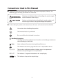
Conventions Used in This Manual
■■ To prevent injury to the operator and others, and to prevent property damage, the
following types of safety precautions are indicated:
WARNING
CAUTION
Warnings are indicated when mishandling this product might
result in death or serious injury.
Cautions are indicated when mishandling this product might result
in minor injury to the user, or physical damage to the product.
■■ In describing the product, this manual uses the icons and conventions listed below.
Use caution when handling the product.
The indicated action is prohibited.
Be sure to follow the indicated instructions.
Handling Precautions:
Handling Precautions indicate items that the user should pay attention to
when handling the CMS1500.
Note:
Notes indicate information that might benefit the user.
This indicates the item or page that the user is requested to refer to.
(1), (2), (3)
The numbers with the parenthesis indicate steps in a sequence or
indicate corresponding parts in an explanation.
03, P-07
This indicates 7-segment indication on the setup display.
key
This indicates a key on the setup display.
i
Safety Precautions
WARNING
Do not use this device for oxygen or flammable gases.
Materials of this device are not selected on the premise that it is used for oxygen
or flammable gases. In addition, oil-inhibiting treatment is not performed to the
gas-contacting sections.
CAUTION
Prevent foreign matter from entering the device.
If the rust, water droplet, oil mist or dust in the piping flows into the device, measurement error might occur and result in damaging the device.
If there is a possibility that any foreign matter flows into the device, provide a
filter, strainer or mist trap capable of eliminating more than 1µm foreign matter at
the upstream, and periodically inspect and replace the filter.
This device is a precision instrument. Do not drop it nor subject it to shock. Doing
so might damage the device.
Do not operate the keys with a propelling pencil or sharp-tipped object. Doing so
might cause faulty operation.
Do not use this device outside of the operating pressure range. Also, do not subject this device to a pressure above the pressure resistance.
Doing so might damage this device.
Do not peel off the pipe connector port seals until immediately before you connect the piping. Doing so might allow foreign objects to enter the connector port
and cause defective operation.
When connecting piping, fasten the flange section of the pipe connector port,
and turn the pipe side to connect.
When mounting the device, firmly fasten to prevent vibration.
Do not overapply sealant. Allowing entry of dirt or burrs inside the pipes might
cause error.
Mount this device horizontally. However, do not mount it horizontally with the
display facing down. Doing so might cause device failure. If it is mounted vertically, a measurement error could occur.
When using a relay as the contact for integrated count reset input, use a relay
(gold contact type) for low currents.
Otherwise, defective contact may cause the device to malfunction.
ii
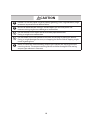
CAUTION
If there is a risk of a power surge caused by lightning, use a surge absorber (surge
protector) to prevent fire or device failure.
Be sure to check that the wiring is correct before you turn the power ON.
Incorrect wiring might cause damage or malfunction.
Do not remove a resin cover and disassemble pipe connections.
Doing so might case malfunction.
Do not hold a resin cover portion at the time of carrying or piping this device.
Doing so might damage the cover, or dropping the device due to slipping might
result in getting hurt.
Make sure that the selected analog output type matches the input type of the
receiving device. The output-receiving device could be damaged if the analog
output type selection is incorrect.
iii
Contents
Conventions Used in This Manual
Safety Precautions
Chapter 1.INTRODUCTION
■■Introduction. . . . . . . . . . . . . . . . . . . . . . . . . . . . . . . . . . . . . . . . . . . . . . . . 1
■■Features. . . . . . . . . . . . . . . . . . . . . . . . . . . . . . . . . . . . . . . . . . . . . . . . . . . . 1
■■Model selection guide. . . . . . . . . . . . . . . . . . . . . . . . . . . . . . . . . . . . . . . 1
Chapter 2.NAMES AND FUNCTIONS OF PARTS. . . . . . . . . . . . . . . . . . . . . . . . . 2
Chapter 3.MOUNTING AND WIRING
■■Mounting . . . . . . . . . . . . . . . . . . . . . . . . . . . . . . . . . . . . . . . . . . . . . . . . . . 4
■■Pipes. . . . . . . . . . . . . . . . . . . . . . . . . . . . . . . . . . . . . . . . . . . . . . . . . . . . . . . 5
■■Wiring . . . . . . . . . . . . . . . . . . . . . . . . . . . . . . . . . . . . . . . . . . . . . . . . . . . . . 9
Chapter 4.METHOD OF OPERATION
■■State transition diagrams . . . . . . . . . . . . . . . . . . . . . . . . . . . . . . . . . 12
■■Function setup . . . . . . . . . . . . . . . . . . . . . . . . . . . . . . . . . . . . . . . . . . . 13
■■Parameter setup. . . . . . . . . . . . . . . . . . . . . . . . . . . . . . . . . . . . . . . . . . 16
■■Display OFF mode . . . . . . . . . . . . . . . . . . . . . . . . . . . . . . . . . . . . . . . . 17
■■Totalization . . . . . . . . . . . . . . . . . . . . . . . . . . . . . . . . . . . . . . . . . . . . . . 17
■■Resetting the count for integrated flow /
integrated flow countdown . . . . . . . . . . . . . . . . . . . . . . . . . . . . . . . 17
■■Event standby. . . . . . . . . . . . . . . . . . . . . . . . . . . . . . . . . . . . . . . . . . . . 17
■■Event ON delay . . . . . . . . . . . . . . . . . . . . . . . . . . . . . . . . . . . . . . . . . . . 17
■■Flowrate zero calibration. . . . . . . . . . . . . . . . . . . . . . . . . . . . . . . . . . 18
Chapter 5.TROUBLESHOOTING
■■Remedying problems . . . . . . . . . . . . . . . . . . . . . . . . . . . . . . . . . . . . . 19
Chapter 6.SPECIFICATIONS
■■General specifications. . . . . . . . . . . . . . . . . . . . . . . . . . . . . . . . . . . . . 20
■■External dimensions . . . . . . . . . . . . . . . . . . . . . . . . . . . . . . . . . . . . . . 22
■■Korean certification mark . . . . . . . . . . . . . . . . . . . . . . . . . . . . . . . . . 22
■■Pressure loss . . . . . . . . . . . . . . . . . . . . . . . . . . . . . . . . . . . . . . . . . . . . . 23
iv
Chapter 1. INTRODUCTION
■■ Introduction
The CMS1500 Gas mass flow meter uses µFTM (Micro FlowTM)
sensor in the sensing section. The µF sensor is a thermal flow speed
sensor made using proprietary technology. Integrating this ultraminute flow speed sensor with high-grade channel design technology
has achieved high accuracy and high rangeability.
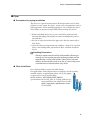
■■ Features
• Incorporates a µF sensor made possible by silicon micro-machining
technology and thin-film forming technology.
One side of the µF sensor is a mere 1.7 mm, and at a thickness of
0.5 mm, this thermal flow speed sensor exhibits high sensitivity and
response.
• As the CMS1500 is a mass flow meter, it is not influenced by temperature nor pressure.
• High accuracy of ±5 %RD* and high rangeability of 50:1.
• Models with display meter are provided with extensive functions
to suit a wide range of applications: analog output, event output,
integrating/reverse-integrating display, output scaling, gas type
selection.
• Through the RS-485 communications, the integrated flowrate can
be read out correctly.
Note
• * "RD" (Reading) indicates the accuracy of the read value.
■■ Model selection guide
The following shows the model Nos. for this flow meter:
Basic
Model Mate- Connection Gas
model Flowrate
range
type
rial
method type
No.
Output
Optional
function Appended
No.
1 2 3 4
CMS
1500
B
R
A
R
N
2
1
0
0
0
D
Y
0
Note
Description
Gas Mass Flow Meter
Standard flowrate range 0 to 1500 L/min (standard)*
With display (flow direction: left to right)
With display (flow direction: right to left)
Aluminium
Rc1
Air / Nitrogen, Argon,Carbon dioxide (CO2)
Analog output 0-5 Vdc, 1-5 Vdc, 4-20 mA
With RS-485 communications
Without optional function
Additional treatment not supported
Without options
Inspection certificate provided
Traceability certification provided
Product version
refers to a flowrate after conversion to 20˚C in
• * "L/min(standard)"
air 101.325 kPa (1 atm).
1
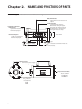
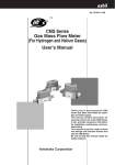
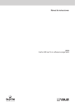
Chapter 2. NAMES AND FUNCTIONS OF PARTS
The following describes the names and functions of parts:
EV1, EV2 indicators:
Lights when event 1 and event 2 are
output.
Flowrate display:
7-segment display indicates
flowrate by a 4-digit number.
While function setup, the upper
two digits on the display indicate
the function type, and the lower
two digits indicate the setup.
Instantaneous flowrate
indicator lamp:
Lights when instantaneous
flowrate is displayed.
Massflow
Integrated flowrate
indicator lamp:
Lights when integrated
flowrate is displayed.
L/min
EV1
X10L
EV2
DISP
MODE
Display meter
ENT
key:
Change the display.
DISP
MODE
key:
Select the setup mode.
keys:
Select the mode and the mode setup.
ENT
key:
Fix a mode setup.
Signal connector:
Connects the power supply
and output signals.
Pipe connection outlet:
The gas outflow is
connected here.
Pipe connection inlet:
The gas inflow is
connected here.
〔IN〕
2
〔OUT〕
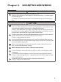
Chapter 3. MOUNTING AND WIRING
WARNING
Do not use this device for oxygen or flammable gases.
Materials of this device are not selected on the premise that it is used for oxygen
or flammable gases.
In addition, oil-inhibiting treatment is not performed to the gas-contacting sections.
CAUTION
Prevent foreign matter from entering the device.
If the rust, water droplet, oil mist or dust in the piping flows into the device, measurement error might occur and result in damaging the device.
If there is a possibility that any foreign matter flows into the device, provide a filter, strainer or mist trap capable of eliminating more than 1 µm foreign matter at
the upstream, and periodically inspect and replace the filter.
Do not use this device outside of the operating pressure range. Also, do not subject this device to a pressure above the pressure resistance.
Doing so might damage this device.
Do not peel off the pipe connector port seals until immediately before you connect the piping. Doing so might allow foreign objects to enter the connector port
and cause defective operation.
When connecting piping, fasten the hexagonal section of the pipe connector
port, and turn the pipe side to connect.
When mounting the device, firmly fasten to prevent vibration.
Do not overapply sealant. Allowing entry of dirt or burrs inside the pipes might
cause error.
Do not hold a resin cover portion at the time of carrying or piping this device.
Doing so might damage the cover, or dropping the device due to slipping might
result in getting hurt.
Do not remove a resin cover and disassemble pipe connections.
Doing so might cause malfunction.
3
Chapter 3. MOUNTING AND WIRING
■■ Mounting
●● Installation site
Avoid mounting the CMS1500 in the following locations:
1. Locations where operating temperature falls below -10 ˚C and rises
above +60 ˚C
2. Locations where operating humidity exceeds 90 % RH
3. Locations subject to sudden changes in temperature and condensation
4. Locations subject to corrosive gases and flammable gases
5. Locations where there are lots of conductive substances (e.g. dust,
salt or iron dust), water droplets, oil mist or organic solvents
6. Locations subject to vibration or shock
7. Locations subject to direct sunlight
8. Locations splashed by water or rain
9. Locations subject to splashing by fluids (e.g. oil, chemicals.)
10. Locations where strong magnetic or electrical fields are generated
4
Chapter 3. MOUNTING AND WIRING
■■ Pipes
●● Precautions for piping installation
This device is a precision instrument. If foreign matter such as dust,
oil mist or water enters the device, it may cause measurement error or
faulty operation. When installing piping, be sure to follow the procedures below to prevent foreign matter from entering the device.
1. Before installing the device, be sure to flush the upstream and
downstream piping thoroughly to remove welding fume particulate and dust.
2. Be sure to wipe the inside of the pipe to be directly connected to
this device.
3. After the above two operations are complete, check to be sure that
there is no welding fume particulate or dust, and then install the
device.
Handling Precautions
• If foreign matter cannot be fully eliminated by flushing or
wiping, or if the regular presence of foreign matter can be
expected, be sure to install a filter. If dust, oil or moisture
adheres to the metallic mesh or to the μF sensor chip, measurement error or device failure may result.
●● Filter installation
For a dedicated filter, contact the azbil Group.
For applications with compressed air or propane, which regularly
contain oil mist, or applications where rust in the piping
is expected, be sure to install a filter.
Model Number : MFF100NAG/MFF100NSG
Specifications: For details, refer to "Lineup of Mist Separators and Filters for Micro Flow Sensors,"
Azbil Corporation specifications sheet
CP-SS-1824E.
5
Chapter 3. MOUNTING AND WIRING
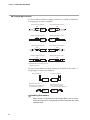
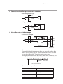
●● Straight pipe section
In case of different diameter piping (diameters A and B are different),
a straight pipe section is required.
Upstream side enlarged
Downstream side reduced
5D
A
3D
CMS
B
Different diameter socket
CMS
Different diameter socket
5D
A
3D
CMS
B
Upstream side reduced
CMS
Downstream side enlarged
3D
B
CMS
Different diameter socket
CMS
B
A
Different diameter socket
5D
3D
B
A
A
B
5D
A
A
B
CMS
CMS
B
A
D indicates the connecting port size.
CMS1500: 25 mm
In case of same diameter piping (diameters A and B are the same), a
straight pipe section is not required.
Upstream elbow
Downstream elbow
A
A
B
CMS
Upstream ball valve
(a valve whose structure does
not disturb the gas flow)
A
B
CMS
CMS
B
Downstream ball valve
(a valve whose structure
does not disturb the gas flow)
CMS
B
A
Handling Precautions
• When using a valve that disturbs the gas flow, such as a butterfly valve, put a 5D straight pipe section between the CMS
and the valve.
6
Chapter 3. MOUNTING AND WIRING
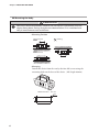
• Coating sealant
Coat with an appropriate amount of sealant. Do not coat the top two
threads of the screw. Remove any dirt or burrs from inside the pipes.
OK
Correct
Wrong
Sealant
Sealant
• Connecting Pipes
Connect pipes while gripping the hexagonal section of the pipe
connection port with a spanner or wrench.
Resin cover
Flange
Hexagonal section
Pipe
Body
Handling Precautions
• Do not grip and turn the body. Doing so might damage the
body or cause leakage.
• When connecting pipes, do not grasp the resin cover. Doing
so might damage the cover.
• Gas flow
Gas
Gas
Handling Precautions
• When feeding gas into the meter, make it flow following the
arrow on the side of the channel. If gas is fed in the opposite
direction, the gas flow cannot be measured accurately.
7
Chapter 3. MOUNTING AND WIRING
●● Mounting the body
CAUTION
Mount this device horizontally. However, do not mount it horizontally with the
display facing down. Doing so might cause device failure. If it is mounted vertically, a measurement error could occur.
• Mounting Position
OK Correct
Wrong
OK Correct
Massflow
L/min
EV1
X10L
EV2
DISP
MODE
ENT
• Mounting
Install this device from the rear by the four M5 screws using the
mounting holes on the base of the device. (M5: depth 10 mm)
22
Hole dimensions Unit: mm
5.5
140
8
Chapter 3. MOUNTING AND WIRING
■■ Wiring
CAUTION
When using a relay as the contact for integrated count reset input, use
a relay (gold contact type) for low currents.
Otherwise, defective contact may cause the device to malfunction.
If there is a risk of a power surge caused by lightning, use a surge absorber (surge
protector) to prevent fire or device failure.
Be sure to check that the wiring is correct before you turn the power ON. Incorrect
wiring might cause damage or malfunction.
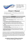
We recommend using a harness with connector (sold separately).
●● Connector pin layout
1
9
View from connector end
2
10
Compatible connector:
DF11-10DS-2C made by HIROSE ELECTRIC CO., LTD.
Item
Harness with dedicated
connector
(One harness is required
for one CMS unit.)
Model number
Remarks
81446594-005
Harness (2 m) for model without communications -plain wire termination
81446594-006
Harness (5 m) for model without communications -plain wire termination
81446594-007
Harness (2 m) for model with communications -M3.5 Y-terminals
81446594-008
Harness (5 m) for model with communications -M3.5 Y-terminals
• Connector signal names
Pin number Signal name
Description
1
DC OUT+
Instantaneous flowrate output +
2
DC OUT-
Instantaneous flowrate output -
3
V+
Power + (12 to 24 Vdc)
4
GND
Power GND
5
DA
6
DB
For RS-485 communications
7
DIN
Integration count reset input
8
EV2
Event 2 output/Integration pulse output
9
EV1
Event 1 output/Serial data output
10
EVCOM/SG
Event output common/SG for RS-485
Remarks
Connect RS-485 model only
9
Chapter 3. MOUNTING AND WIRING
●● Connection example
1
DC OUT + Brown
2
DC OUT - Red
3
V+
4
GND Yellow
5
DA
Pink
6
DB
Blue
7
DIN
Green
8
EV 2
Gray
9
EV 1
White
Orange
12 to 24 Vdc
Installed externally
10 EV COM/SG
Internal circuit
RS-485
communication
Load (30 Vdc, 50 mA or less)
Load
(30 Vdc, 50 mA
Black or less)
30 Vdc
or less
External connection example
Handling Precautions
• Power source GND, instantaneous flow rate output (-), and
event output common lines are all connected inside this
device. If these lines are connected to an external device
through a common power supply, interference will cause
device failure or faulty operation.
• Take care that the event output does not exceed the output
rating of this device. If a relay is used, the coil should have
a built-in surge absorption diode. Otherwise device failure
could occur.
10
Chapter 3. MOUNTING AND WIRING
●● Connection of totalizer pulse output to a counter.
• Non-voltage input type
8
EV2
10
EVCOM
Input
Counter
0V
• Voltage input type
Pull-up resistor
8
EV2
Counter
EVCOM
10
30 Vdc or less
Input
0V
●● Use of flow rate serial data output
• Connection example
9
EV1
10
EV COM
+5 V
10Ω k
+5 V
10Ω k
RS-232C
driver
RXD
GND
CMS
RTS
CTS
Interface *
Computer
RS-232C port
* Interface section must be made by the user as shown above.
• Communications protocol
Currently displayed instantaneous flow rate data and totalizer flow
data is sent as ASCII code. "F" and the instantaneous flow rate data
is sent first, followed by "T" and the totalizer flow data.
Example: The instantaneous flow rate is 100. L/min (standard), and
the totalizer flow is 100 x 10 L.
100X10 L
Totalizer flow rate
100. L/min (standard)
Instantaneous flow rate
0Dh
0Ah
• Communications specifications
Item
Communications system
Transmission speed
Character length
Stop bit
Parity
Data transmission cycle
Description
RS-232C, start-stop transmission
9600 bps
8 bits
2
None
100±10 ms
11
Chapter 4. METHOD OF OPERATION
CAUTION
Do not operate the keys with a mechanical pencil, screwdriver, or other sharptipped object. Doing so might cause faulty operation.
Make sure that the selected analog output type matches the input type of the
receiving device. The output-receiving device could be damaged if the analog
output type selection is incorrect.
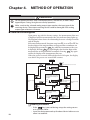
■■ State transition diagrams
Upon power-up, with the factory settings, the instantaneous flow rate
is displayed and the instantaneous flow rate indicator lamp lights up.
The diagram below shows the relationship between a change in mode
and the display.
If the measurement mode (function setup item 02) is set to 01 or 02, the
last four digits of the integrated flow or integrated flow countdown can
be displayed by pressing the DISP key while the instantaneous flow rate
is displayed. Pressing DISP key again displays the first four digits of the
integrated flow or integrated flow countdown. Pressing DISP key again
returns the display to the instantaneous flow rate.
When the power is turned OFF and then back ON again, the display
state before the power was turned OFF resumes.
Power ON
ENT
MODE
key Instantaneous flow rate display
+
key
key held down for 3 s or more
L / min
X10 L
DISP
DISP
key
Integrated flow or integrated
flow countdown display, last
four digits
key
+
L / min
Function setup
mode
MODE
key
DISP
ENT
X10 L
Dot display ON
DISP
key
DISP
key
DISP
key
ENT
+
L / min
MODE
X10 L
Dot display OFF
DISP
key held down for Parameter setup
3 s or more
mode
key
Integrated flow or integrated
flow countdown display,
first four digits
key
key
DISP
key
DISP
key
key
key held
down for 3 s or
more
key
Handling Precautions
12
• If the
key is pressed during setup, the setting returns
to its previous value.
• Leave the device powered up for about 30 min before use to
allow it to stabilize.
Chapter 4. METHOD OF OPERATION
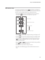
■■ Function setup
To enter the setup mode, press the
key. The first two digits on
the display blink. The first two digits identify the function setup item,
and the second two digits indicate the setting for that item.
• Pressing the
Pressing the
key moves the display to the next setup item.
key moves to the previous setup item.
key
Key lock setup
key
key
Measurement mode setup
key
key
Event 1 type setup
Communications setup
key
• Pressing
key when 32 is displayed changes the display to 0 1.
• Pressing
key when 0 1 is displayed changes the display to 32.
• When the first two digits display the desired setup item, press the
key while it is blinking. This selects the setup item, and the
second two digits blink.
• Press the
and
keys to select the desired setting, and then
press
key. All four digits light up.
• Check that the item and the setting are correct.
• The table on the following pages shows all the functions and settings.
13
Chapter 4. METHOD OF OPERATION
●● Function setup menu
Item
Function
Setting
Setting description
Factory
setting
01
Key lock
00
01
Key lock disabled
Lock ON
00
02
Measurement
mode
00
01
Only instantaneous flow rate is measured.
Instantaneous flow rate and integrated
flow are measured.
Instantaneous flow rate and integrated
flow countdown are measured.
01
02
Remarks
When key lock is ON, other
function and parameter
settings can be checked,
but cannot be changed.
03
Event 1 type
(EV1)
00
01
02
03
04
05
06
Not used
Instantaneous flow rate upper limit value
Instantaneous flow rate lower limit value
Integrated flow count up
Reverse integrated flow count down
Flow rate data serial output
Error output
00
04
Event 2 type
(EV2)
00
01
02
03
04
05
06
07
Not used
Instantaneous flow rate upper limit value
Instantaneous flow rate lower limit value
Integrated flow count up
Reverse integrated flow count down
Totalizer pulse output rate 10 L/1 pulse
Totalizer pulse output rate 100 L/1 pulse
Totalizer pulse output rate 1000 L/1 pulse
00
05
ON delay setting
(EV1)
00
0
Disabled
ON
00
Valid only when function
03 is set to 0 1 or 02.
06
ON delay setting
(EV2)
00
01
Disabled
ON
00
Valid only when function
04 is set to 0 1 or 02.
07
Event standby
setting
00
01
Disabled
ON
00
Valid only when function
03 or 04 is set to 02.
Page 17
08
Gas type
selection
00
01
02
08
Air/nitrogen
Argon
Carbon dioxide (CO2)
User specified
00
When gas type is changed,
sometimes flowrate measurement rate changed.
Page 20
If set to “08,” also set the gas
type conversion factor in
parameter setup mode. *2
09
Analog output
scaling
00
01
02
03
04
0 to 1500 L/min
0 to 900 L/min
0 to 600 L/min
0 to 300 L/min
Desired scaling
00
*1
10
Analog output
type selection
00
01
02
0 to 5 V
1 to 5 V
4 to 20 mA
02
Make sure that the selected
analog output type matches
the input type of the receiving
device.
11
Reference
temperature
00
to
35
0 to 35 °C (in 1 °C intervals),
101.325 kPa (1 atm) standard
20
12
Low flow cutoff
00
01
No low flow cutoff
Cutoff below the rated minimum display
(15 L/min)
15 L/min
37.5 L/min
75 L/min
01
02
03
04
14
Integrated flow count,
integrated flow countdown,
and totalizer pulse output
settings are effective only
when function setup item
02 is set to 0 1 or 02.
Integrated flow count and
integrated flow countdown
cannot be set simultaneously.
If gas type (function setup 08)
is set to "user specified"(08),
the low flow cutoff is the
amount set here multiplied by
CF, the gas type conversion
(parameter setup P-08).
01 and 02 are the same value.
Chapter 4. METHOD OF OPERATION
Setting
Setting description
Factory
setting
Item
Function
30
Communications
address
31
Transmission
speed
00
01
02
9600 bps
4800 bps
2400 bps
00
32
Data format
00
01
8 data bits, even parity, 1 stop bit
8 data bits, no parity, 2 stop bits
00
00 Communication function disabled
0 1 to Communication address
99
Remarks
00
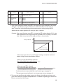
*1 I f gas type selection (function setup 08) is changed, the measurable flow rate range
changes as specified on page 21 ("Maximum measurable flow rate for each gas
type"). However, scaling according to the analog output scaling setting will be
applied to the output regardless of what gas type is selected.
Example: I f gas type (function setup 08) is changed to 02 (carbon dioxide (CO2)), the
measurable flow rate range changes to 0 to 900 L/min. If scaling is set to 00
(0 to 1500 L/min), the 0 to 5 V output will be as shown below.
Voltage output (V)
5.00
3.00
Measurement range
of carbon dioxide (CO2)
900
1500
Flowrate (L/min)
It the output type is 0 to 5 V, and if output scaling is used, the maximum
output voltage can be calculated as follows.
• When gas types 00 to 02 are selected
Max. measurable flow rate for the gas
X5V
Scaling upper limit value
• When gas type 08 is selected
Max. measurable flow rate for the gas
1
X
Scaling upper limit value Gas type conversion factor
X5V
For the maximum measurable flow rate for each gas, see page 20.
The gas type conversion factor is set in parameter setup; see pages 16.
*2 T he user can specify any desired gas conversion factor to handle gas mixtures and
gases other than the standard compatible ones. For details regarding gas conversion
factors, contact the Azbil Group.
15
Chapter 4. METHOD OF OPERATION
■■ Parameter setup
If the key lock function is ON, parameter settings cannot be changed.
To enter the parameter setup mode, hold down the E N T and
keys simultaneously for at least three seconds. If conditions do not
allow parameter setup, "P---" is displayed.
Otherwise, in parameter setup mode, P-** is displayed. The last two
digits identify the parameter setup item.
Pressing the
key moves the display to the next setup item.
Pressing the
key moves to the previous setup item.
The currently set value for that item is displayed.
If the ENT key is pressed again, the last digit blinks.
MODE key
key, the blinking cursor moves to the left. To
If you press the
change the setting at each of these digits, use the
and
keys.
To change the setting to the displayed value, press the E N T key.
If event type (function setup 03 or 04) has been set to 03 or 04, the
setting of 8-digit numbers is necessary in P-0 1, 02 and 07. To do this,
switch between the first 4 digits and the last 4 digits as shown below.
Last four digits
key
First four digits
key
Dot indicates display
of last four digits
Whether parameters P-0 1 to P-09 are displayed for setup depends
upon the function settings. The following tables show the parameters
and the necessary function settings.
Parameter
P-01
P-02
Description
Factory setting
Setting range
Event output 1 setting value
(EV1)
00000000. 0 to 99999999 (X 10 L)
Event output 2 setting value
(EV2)
00000000. 0 to 99999999 (X 10 L)
0. 0 to 9995 (L/min )
0. 0 to 9995 (L/min)
Conditions for display
(function settings)
Item 03 is 0 1 or 02
Item 03 is 03 or 04
Item 04 is 0 1 or 02
Item 04 is 03 or 04
P-03
EV1 hysteresis
50. 0 to 100 (L/min)
Item 03 is 0 1 or 02
P-04
EV2 hysteresis
50. 0 to 100 (L/min)
Item 04 is 0 1 or 02
P-05
EV1 ON delay
0 0 to 60 (s)
P-06
EV2 ON delay
0 0 to 60 (s)
P-07
Initial value for integrated
flow countdown
P-08
Gas type conversion factor
P-09
Analog output scaling
00000000. 0 to 99999999 (X 10 L)
Item 03 is 0 1 or 02
Item 04 is 0 1 or 02
Item 02 is 02
1.000 0.100 to 8.000
Item 08 is 08
100 10 to 250 (%)
Item 09 is 04
Handling Precautions
• Set a value for event output that is within the measurable range.
16
Chapter 4. METHOD OF OPERATION
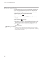
■■ Display OFF mode
If the DISP key is held down for at least three seconds, all display
is turned off except for the instantaneous flow rate indicator lamp,
which blinks.
If the DISP key is pressed in display OFF mode, the instantaneous
flow rate is displayed.
■■ Totalization
If integrated flow exceeds 99999999, the count returns to 0 and
counting continues. When this happens, event output for integrated
flow remains OFF until the set value is reached again.
If the integrated flow countdown reaches 0, counting stops.
■■ Resetting the count for integrated flow / integrated flow countdown
To reset the count, hold down the
and
keys simultaneously for at least one second while the integrated amount or integrated
countdown amount is displayed. The integrated flow count is reset to
0, and the countdown is reset to the default. After reset counting up
or counting down resumes.
■■ Event standby
Event standby operates only on the basis of the instantaneous flow
rate lower limit. This function prevents an erroneous low flow alarm
when there is no gas flow because the device has just started up, for
example. After the power is turned ON, and until the instantaneous
flow rate has exceeded the value set for the event lower limit, there is
no event action. After the instantaneous flow lower limit has been
exceeded once, event action operates normally.
Instantaneous flow rate
value
No event action
Event action
Lower limit setting
value
Time
ON
Event output
OFF
■■ Event ON delay
ON delay times (0 to 60 s) can be set for both events 1 and 2.
ON
Event output
ON delay time
OFF
Instantaneous
flow rate value
Event ON
Time
Event detected
17
Chapter 4. METHOD OF OPERATION
■■ Flowrate zero calibration
If the indicated flow rate is not zero even though the actual flow rate
is zero, and it seems possible that the sensor's zero point may have
shifted, try the following procedure for flow rate zero calibration.
(1) Display the flow rate or integrated flow amount.
(2) Press and hold the
ENT
key.
(3) After approx. 10s have elapsed, 0. CAL blinks on the flow rate
display.
(4) Press and hold
ENT
key again.
(5) After approx. 1 second, 0. CAL stops blinking and remains lit. The
amount of sensor output at this moment is now treated as zero.
(6) Press DISP key to return to the instantaneous flow rate or integrated flow display.
Handling Precautions
• Use flow rate zero calibration only after ensuring that the flow
path contains only the gas being measured, and after stabilizing
the actual flow rate at zero.
18
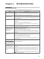
Chapter 5. TROUBLESHOOTING
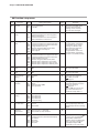
■■ Remedying problems
Refer to the following table if a problem occurs:
Problem
Countermeasure
Nothing on the display.
• Make sure that power with the correct voltage and polarity is being supplied.
• Make sure that connectors are correctly connected.
ALH 1 is displayed.
The instantaneous flow rate has exceeded 120 % of the measurement range.
Reduce the flow rate so that it is within range, and normal operation will
automatically resume.
Err 1 is displayed.
Sensor error
• Make sure that gas is not flowing back, or the gas flow direction is not
reversed.
• Make sure that an excess current is not flowing.
If the unit is not restored after turning the power OFF, contact the azbil
Group and ask for repair.
Err2 is displayed.
Memory data error
Contact the azbil Group and ask for repair.
Signal is output even
though the flowrate
should be zero.
• Check the piping for any gas leaks.
• Check the wiring to make sure that it is correct.
• If the device is mounted vertically, mount it horizontally. If it seems possible that the sensor's zero point has shifted, try flow rate zero calibration
(page 18).
Flow rate has deviated
excessively.
• Check the piping for any gas leaks.
• Check the piping and connection ports for dirt, oil or other foreign matter.
If oily, contact the azbil Group and ask for repair.
• Check the wiring to make sure that it is correct.
• Check if the flow rate is extremely unstable or greatly exceeds the measurement range.
The displayed value is
lower than expected.
• Check if the gas contains foreign matter such as dust, rust, oil or water.
If it seems that there is foreign matter in the flow meter, contact the azbil
There should be no flow Group and ask for repair.
but the indicated flow
rate is higher than zero.
The indicated instanta- • Check the piping for any gas leaks, and check if the gas flow has actually
stopped.
neous flow rate is zero,
but the integrated flow • Even if the instantaneous flow rate display is zero, a minute flow smaller
counting up or, counting than the minimum display value of the flowmeter might be present. For
integrated measurements, even a flow under the minimum display value is
down.
counted.
Set the low flow cutoff to prevent integrated flow countup or countdown.
Function setup, page 13
19
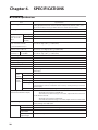
Chapter 6. SPECIFICATIONS
■■ General specifications
Item
Specifications
Applicable gas
Air/nitrogen, Argon, Carbon dioxide (CO2) (Not applicable to oxygen and flammable gases) Gas must not contain corrosive components (chlorine, sulfur, acid,
etc.). It also must be a clean gas which does not contain dust or oil mist.
Flow range *1
0 to 1500 L/min (standard)
“Standard” indicates the standard calibration condition (20 °C, 101.325 kPa (1 atm))
Maximum measured Air/nitrogen
flowrate for each gas Argon
(at 20 °C, 101.325
Carbon dioxkPa) *2
ide (CO2)
Measurement accuracy
at 23 °C and 101.325 kPa
(χ : measured flow rate) *3
0 to 1500 L/min
1500 L/min
900 L/min
±1 % FS ±1 digit (30 ≤ χ < 150 L/min)
±5 % RD ±1 digit (150 ≤ χ ≤ 1500 L/min)
±0.1 % FS/ °C ±1 digit (0 ≤ χ < 1125 L/min)
±0.15 % FS/ °C ±1 digit (1125 ≤ χ ≤ 1500 L/min)
Pressure char- Operating pressure ±1 % FS ±1 digit (30 ≤ χ < 150 L/min)
acteristics *5 0 to 0.6 MPa
±5 % RD ±1 digit (150 ≤ χ ≤ 1500 L/min)
Temperature characteristics
between −10 to +60 °C *4
Pressure range
0 to 0.6 MPa
Pressure resistance
1.0 MPa
Rated voltage
12 to 24 Vdc
Supply voltage range
11.4 to 25.2 Vdc
Current consumption
100 mA max.
Sampling cycle
100 ms ±10 ms
Display Flow rate display
4-digit 7-segment LED, selectable between instantaneous flow rate and integrated
flow display.
Instanta- Min. display
neous
Resolution
flow rate
InteDisplay unit
grated
Display range
flow rate
Data storage
Indicator LEDs
15 L/min
5 L/min
10 L
0 to 99999999
Data is written to memory every 10 minutes.
(Integrated flow count or countdown can be reset by control panel key or external
contact input.)
Instantaneous flow rate display, integrated flow display, event 1 & 2 display
Output signal
(instantaneous flowrate output)
If 0-5 or 1-5 Vdc is selected:
• Allowable load resistance 250 kΩ min.
• Even if the measurement range is exceeded, output remains less than 6 V.
If 4-20 mAdc is selected:
• Allowable load resistance 300 Ω max.
• Even if the measurement range is exceeded, output remains less than 24 mA.
Output scaling function *6
Selectable from 0 to 300, 0 to 600, 0 to 900, 0 to 1500 L/min.
Factory setting: 0 to 1500 L/min.
Event output
Number of outputs
2
Type
Open collector (absolute maximum ratings 30 Vdc, 50 mA)
Totalizer pulse
output width
100 ms ± 10 %
Totalizer pulse
output weight
10, 100, 1000 L/1 pulse
20
Chapter 6. SPECIFICATIONS
Item
External input Number of inputs
Remote circuit
type
Specifications
1 (integrated count reset only)
No-voltage contact or open collector
Circuit type on other side:
Contact OFF terminal voltage:
4.5 ± 1 V
Approx. 0.5 mA (current flowing to contact)
Contact ON terminal current:
Allowable ON contact resistance: 250 Ω max.
Allowable OFF contact resistance: 100 kΩ min.
Allowable ON residual voltage: 0.8 V max. (open collector on other side)
Allowable OFF leakage current: 50 μA max. (open collector on other side)
Serial data output
Open collector (rated 30 Vdc, 50 mA)
Gas type switching function
Selection of air/nitrogen, argon, carbon dioxide (CO2), using the control panel
keys.
Gas type setup function
Gas type conversion factor between 0.100 and 8.000 can be set using the control
panel keys.
Electrical connection
• Harness with a special connector (optional)
• Mating connector: Hirose Electric Co. DF-11-10DS-2C
Operating temperature range
-10 to +60 °C
Storage temperature range
-20 to +70 °C
Operating humidity range
10 to 90 %RH (condensation not allowed)
Connection aperture
Rc1
Body material
Aluminum
Cover material
Polycarbonate resin
Mounting position
Horizontal mounting. (Top surface must not face down.) If this device is mounted
vertically, drift may cause erroneous measurement when the actual flow rate is
zero. For details, contact the azbil Group.
Standard compliance
EN61326-1:2006, EN61326-2-3: 2006
Mass
Approx. 3 kg
*1 The flow rate range is for air. Because this device has a gas-type switching function, the device
keys can be used to switch from one gas type to another. For the maximum measurable flow
rate and output voltage for various gas types, see the table below.
Gas type
Maximum measurable flow rate Output voltage Setting and display
[L/min(standard)]
[V]
resolution [L/min]
Air/Nitrogen
1500
Argon
1500
900
Carbon dioxide (CO2)
User specified
1500 [L/min] × conversion factor (C.F.)*
*2
*3
*4
*5
*6
5
5
3
5
5
5
5
5
* Users
can set the conversion factor from 0.100 to 8.000. In addition, analog output scaling
can be changed by using the keys.
Gas types other than those listed above can be handled by using a conversion factor. For details, contact the Azbil Group.
Measured flow rate = χ L/min (standard)
The stated accuracy is for air/nitrogen.
This is the amount of flow rate change at 101.325 kPa with 23 °C as the reference point.
This is the amount of flow rate change at 23 °C with 101.325 kPa as the reference point.
Analog output scaling can be changed by using the keys. If the gas type is changed, the flow
rate measurement range changes accordingly, as shown in the table above. However, with this
function, analog output is scaled according to the analog output scaling setting even if the gas
type is changed.
21
Chapter 6. SPECIFICATIONS
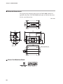
■■ External dimensions
The engineering drawings below show the CMS1500B with left-toright flow direction. The CMS1500R with right-to-left flow direction
has the same dimensions.
Unit: mm
Massflow
Micro Flow
EV1
L/min.
X10L
DISP
MODE
ENT
185
44
127
64
100
EV2
140
2-Rc1
22
4-M5 depth 10 min.
■■ Korea Certifications Mark
22
Chapter 6. SPECIFICATIONS
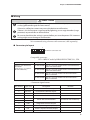
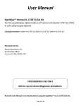
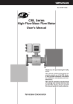
Pressure loss Pa
■■ Pressure loss
4500
4000
3500
3000
2500
2000
1500
1000
500
0.0
CMS1500
Primary pressure
20 kPa
350 kPa
500 kPa
0
300
600
900
1200
1500
Flowrate L/min(standard)
The graph shows the data in air.
The values for the gases other than air can be obtained by multiplying
the specific gravities shown in the table below.
Gas type
Specific gravity*
Argon
1.38
Carbon dioxide
1.53
*With air as 1.0.
Example:The primary pressure is 20 kPa, and the flowrate is 600 L/
min, the pressure loss for argon is calculated as follows:
From the graph of CMS1500, the pressure loss is about 950
Pa when the primary pressure is 20 kPa and the flowrate is
600 L/min.
Multiply this value by 1.38, the specific gravity of argon, and
the result is 950 X 1.38 = 1311 Pa.
23
Revision History of CP-SP-1119E
Printed
Edn.
Aug. 2001
Dec. 2002
Sep. 2003
1
2
3
Apr. 2007
Apr. 2012
Mar. 2013
4
5
6
Revised pages
1
3
5
17
20
ii, 8
1
2, 8, 22
5
11
14
15
14, 15
17
20, 21
21
22
Description
Fully revised by addition of CMS1500B model.
In features, high rangeability added.
7th caution corrected.
In mounting position, new illustration added.
Measurement accuracy, temperature
characteristics, pressure characteristics changed.
Pressure loss added.
Allover revised.
Company name changed.
A CAUTION was changed.
“1 atmospheric pressure” was changed to “1 atm.”
“Model selection guide” table was changed.
“CMS” was deleted from diagrams.
Filter model No. was changed in “Filter installation” section.
A description was added to diagram.
“/pulse” was changed to “/ 1 pulse.”
“Carbon dioxide” was changed to “Carbon dioxide (CO2).”
Notes 1 and 2 were added.
A description was added to “Display OFF mode” section.
Specifications was changed.
Note 2 was changed.
A description was added.
Korea certification mark was added.
Specifications are subject to change without notice.
1-12-2 Kawana, Fujisawa
Kanagawa 251-8522 Japan
URL: http://www.azbil.com
(09)
1st edition: Aug. 2001 ( C )
6th edition: Mar. 2013 ( V )