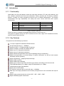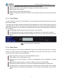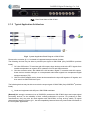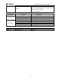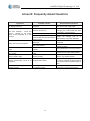
1
Multifunctional IP-to-ASI Adapter GM-2730N User Manual GOSPELL Digital Technology Co., Ltd -1- Safety Instructions Read this manual carefully before start operating the device. Removal of device cover without permission may cause harm to human body and the maintenance bond will be invalidated. Handle the device with care to avoid crashing and falling, or otherwise it may cause hazards to the internal hardware components. Keep all inflammable, metal and liquid materials from dropping into the device casing, or otherwise it may cause damages to the device. Avoid dusty places and places with heating resources nearby, direct projection of sunlight or instant mechanical vibrations for installation of the device. Connect the grounding connector on the rear panel to protect earth contact properly while in operation. Choose proper type of cable connectors for connecting network interfaces of the device. Avoid rapid and frequent power on/off, or it may cause damages to the semiconductor chipsets. Keep proper direction of the power cord when plug into or out from a power socket. Do not touch the power socket with wet hands to avoid electric shocks. Take off all jewelry or ornaments, such as ring, necklaces, watches, bracelets, etc., before operating the device, or otherwise the metal contact may possibly cause short circuit and result in components damage. Make sure the AC power is unplugged in case of operator services within the device casing or close to power supply are needed. Only GOSPELL trained and approved staff is permitted to perform live line operation and maintenance within the device casing. Ensure good ventilation when the device is in operation, or otherwise it may cause damages to the device due to overheating. It is recommended to unplug the power cord from the socket if the device will not be used for a long period of time. -2- GOSPELL Digital Technology Co., Ltd Table of Contents Safety Instructions ........................................................................................................................- 2 Table of Contents ..........................................................................................................................- 3 §1 Introduction .............................................................................................................................- 5 §1.1 Functionality .................................................................................................................- 5 §1.2 Key Features .................................................................................................................- 5 §1.3 Front Panel....................................................................................................................- 6 §1.4 Rear Panel .....................................................................................................................- 6 §1.5 Typical Application Architecture ..................................................................................- 7 §2 Before Use the Device .............................................................................................................- 8 §2.1 Operation Requirements ...............................................................................................- 8 §2.1.1 Requirements for Digital TV Devices ...............................................................- 8 §2.1.2 Requirements for Network Devices ...................................................................- 8 §2.2 System Requirements ...................................................................................................- 8 §3 Operating the Device ...............................................................................................................- 9 §3.1 Quick Start ....................................................................................................................- 9 §3.2 Web Management Operation of GM-2730N.................................................................- 9 §3.2.1 Web User Login ...............................................................................................- 10 §3.2.2 User Management ............................................................................................- 12 §3.2.2.1 Add new user ........................................................................................- 13 §3.2.2.2 Edit users’ information ..........................................................................- 13 §3.2.2.3 Delete a user..........................................................................................- 14 §3.2.3 Basic parameter setting ....................................................................................- 15 §3.2.3.1 IP setting ...............................................................................................- 15 §3.2.3.2 MAC address setting .............................................................................- 16 §3.2.3.3 Parameter setting about system clock ...................................................- 16 §3.2.4 Advanced Parameter setting.............................................................................- 17 §3.2.4.1 Import/export/reset the parameters .......................................................- 17 §3.2.4.2 Back-up/recover the parameters ...........................................................- 20 §3.2.4.3 Upgrade/back-up the software ..............................................................- 21 §3.2.4.4 Device authorization .............................................................................- 22 §3.2.4.5 Device control .......................................................................................- 23 §3.2.5 Input/output setting ..........................................................................................- 24 §3.2.5.1 IGMP Settings .......................................................................................- 24 §3.2.5.2 Ethernet interface parameter checking and setting ...............................- 24 §3.2.5.3 ASI parameter checking and setting......................................................- 25 §3.2.6 Multiplexing setting of Programs ....................................................................- 27 §3.2.6.1 General setting ......................................................................................- 27 §3.2.6.2 PID mapping function ...........................................................................- 29 §3.2.6.3 PSI information insertion ......................................................................- 30 §3.2.6.4 NIT edit .................................................................................................- 33 §3.2.6.5 Input program .......................................................................................- 35 §3.2.6.6 Output service .......................................................................................- 39 §3.2.7 Scrambling Setting...........................................................................................- 45 §3.2.7.1 General Setting .....................................................................................- 45 §3.2.7.2 CAS Configuration ...............................................................................- 46 §3.2.7.3 Services Scrambling Setting .................................................................- 48 §3.2.8 Monitoring .......................................................................................................- 51 -3- GOSPELL Digital Technology Co., Ltd §3.2.8.1 Alarms ...................................................................................................- 51 §3.2.8.2 Bitrate Monitor .....................................................................................- 53 §3.3 Front Panel Operation of GM-2730N .........................................................................- 58 Annex A: Technical Specifications .............................................................................................- 60 Annex B: Frequently Asked Questions.......................................................................................- 62 Postscript ........................................................................................................................................ 63 -4- GOSPELL Digital Technology Co., Ltd §1 Introduction §1.1 Functionality GM-2730N is an IP-to-ASI adapter, which can send eight channels of TS from ASI interfaces, and then multiplex, scramble and insert local information. Finally, transform the TS stream to UDP/IP packets. It adopts our newly developed functions such as “Module Management”. The flexible customization and high expansibility can satisfy the user’s current and future DTV system requirements. License Functionality Remark License 1 1*scramble License mode 2 License 2 2*scramble License mode 3 License 3 3*scramble License mode 4 License 4 4*scramble License mode 5 Table 1 License Type List The device has no scramble functionality without license. License mode is 1. The product is applied mainly to the DTV network head end room, edge of DTV backbone network, and DTV branch head end room. §1.2 Key Features This product has the following key features: 1 IP input, support the standard RTP/UDP format IP input data rate range: 1~800Mbps Payload of UDP: 7 of 188-byte-length TS packets Support multiplex, scramble and PSI/SI process Support up to 512 programs scrambled Support up to 512 program multiplexed Support SI/PSI auto-generation and manual uploading during re-multiplexing Support auto-generation or manual editing of network information, as well as local network information sectors uploading Support PID filtering,mapping and pass-through Support PCR correction Support DVB-CSA scrambling Support up to 4 simul-crypt CAS, the CAS crypt number is according to the license mode Total EMM bandwidth up to 3 Mbps, single CAS bandwidth up to 1 Mbps 188/204 packet length (self-adaptive) Support up to 8 ASI outputs The effective output bit rate for each ASI data: <=100Mbps Data input and output parameters can be flexibly configured and it can auto-detect the input bit stream Support many network protocols, such as UDP、ARP、ICMP、IGMP Support HD/SD program transmission -5- GOSPELL Digital Technology Co., Ltd Support Web/SNMP-based management and online remote update Support both Chinese and English in web page and related technical document Support power-down memory Support device configuration import/export Powerful background configuration function and web monitor system, ensure the device’s high stability §1.3 Front Panel As shown in figure 1, there are one LCD display、one 6-key keypad and three LED indicators on the front panel of GM-2730N. The model type and logo notification information will be displayed on the LCD screen during the device initialization stage. User can check part of the working status of device, and set part of the parameters of GM-2730N by exploring a menu realized by buttons/LCD screen after system initialization, see section §3.3 for details. The POWER LED will be light if the device powers on successfully. The STATUS LED will show some working status of the device, see section §3.3 for details. The ALARM LED will indicate warning messages of the device, if exists, see section §3.3 for details. Fig.1 Front Panel View of GM-2730N §1.4 Rear Panel As shown in figure 2, the rear panel of GM-2730N consists of one power supply connector, one power switch, one RJ45 connector for management, eight BNC ASI connectors for data input, one RJ45 connector for data output, and a grounding point. Power Input Port: To connect to 100~240V 50/60Hz AC input; Power Switch: To turn GM-2730N on or off; Management Port: RJ45 interface, to connect to management server via 100BaseT or Gigabit Ethernet; Data input Port: RJ45 interface, to connect to data source devices of GM-2730N; ASI output Port: BNC connector, to connect to data destination equipments of GM-2730N; Grounding Point: To connect the device with conductive earth. Please make sure of proper grounding of the device before start operating it for the safety of the operators and the device itself! -6- GOSPELL Digital Technology Co., Ltd Fig.2 Rear Panel View of GM-2730N §1.5 Typical Application Architecture Fig.3 System Application Block Diagram of GM-2730N Please refer to section §2.1.1 for details of supported transport stream formats. The following devices may be able to provide input signal to GM-2730N (Only GOSPELL® products listed): 1. GC-18xx IRD series: TS receivers with ASI output, these devices receive the DTV signals from satellite transponders or superior DTV networks via HFC and SDH networks. 2. GN-18xx encoder series, GN-1864A HD h.264 encoder: Digital TV encoders with ASI outputs, these devices encode analogue or uncompressed audio/video signals into compressed digital transport streams (TS). 3. GM-27xx ASI/IP adapter series: these devices transform the input ASI signals to IP signals, and then send it to GM-2730N via IP port. The following devices may be able to receive the output signal of GM-2730N (Only GOSPELL® products listed): 1. Head-end equipment with ASI port: GM-2730N modulator. [Remark] We strongly recommend use of GOSPELL products as GM-2730N’s input and output signal processing devices, as the reliability of their unified performance is proven. For products of other manufacturers, they may also be used together with GM-2730N, as long as they satisfy TS signal characteristics stated in section §2.1 , but the compatibility between them may need further verification in the real system applications. -7- GOSPELL Digital Technology Co., Ltd §2 Before Use the Device §2.1 Operation Requirements I In order to ensure proper operation of GM-2730N, there are some requirements for other digital TV and network devices, which will connect with GM-2730N. Please see below for details: §2.1.1 Requirements for Digital TV Devices The output or input transport streams of the devices, which will provide signal source to or receive signal from GM-2730N should comply with the following standards: Transport Stream (TS): This means that the TS stream with one or more channels of digital TV, digital audio broadcasting or any other digital TV services should comply with DVB standard; it must contain PAT and PMT tables, which can completely describe the services. For output IP interface, the TS packets must be encapsulated into UDP datagram. Each output TS should have unique destination IP address (unicast or multicast) and port number. The length of the UDP payload must be 7*188Byte (TS packets), and the payload must be synchronized by sync byte 0x47. GM-2730N may be able to receive/feed multiple transport streams from/into any devices with the TS format complies with the above-mentioned format. §2.1.2 Requirements for Network Devices The switch used for the GM-2730N data output and its destination devices’ (the IPQAM modulator shown in figure 3) output port switch (the “gigabit switch” in figure 3) must be a Layer 3 gigabit switch which can be managed, indispensability to support IGMP2.0. The backboard exchange speed must be higher than 10Gbps; the maximum throughput of each port must be higher than 1Gbps. The switch for the GM-2730N and the managing workstation should be a 100M or gigabit switch, the maximum data exchange speed of each port must be higher than 40Mbps. Normally, It can be the same switch with GM-2730N’s output data switch, the two ports need to be configured to different VLANs. Any hosts that may worsen the network traffic, such as some workstations or servers installed real-time communication tools, streaming media server or WEB server, must not be located at the LAN switch of the output of GM-2730N. These additional signals may cause packet loss, network jitter worsening, and hence due to audio/video distortion at the audiences. §2.2 System Requirements Management workstation must have network connection and support TCP/IP protocol. Microsoft Windows 2000/XP (or higher versions) and Internet Explorer 6.0 (or higher version) are the recommended operating systems of the management workstation, and JavaScript must be supported by the web browser. -8- GOSPELL Digital Technology Co., Ltd §3 Operating the Device §3.1 Quick Start Please follow the procedures below if it is the first time for you to use GM-2730N for constructing DTV head-end system: 1、 Construct your hardware environment, including chassis installation, power supply system deployment, and connecting switches, GM-2730N, the preceding device(s)(e.g. IRD, encoders, etc.), after class device(s), management workstation and CAS server properly (refer to Fig. 3). 2、 Plan for the IP addresses of management port and data port, the cable connectors (ASI coaxial cable, Gigabit network) of each preceding/succeeding devices; as well as number of digital TV transport streams and their output channels. It is recommended to take remark of device addresses, port numbers and other configurations and keep it safely for checking purposes in future. 3、 Boot up each preceding devices of GM-2730N and configure the operating parameters, in order to ensure the proper signal receiving/decoding or output of encoded digital TV transport streams. Please refer to the user manuals of preceding devices provided by their suppliers for detailed configuration. 4、 Boot up GM-2730N, If you have known the management port IP address of the GM-2730N you are currently using, and it is in the same subnet with the management workstation, you may also start configuring GM-2730N from the management workstation directly. Or otherwise you will need to configure the IP address of management port using front panel control (refer to section 错误!未找到引用源。) 5、 Login to the web browser from the management workstation, key in the default user name “admin” and password “000000”; add and configure usernames and passwords of users allowed to access the device (refer to section§3.2.2 ) 6、 Configure the input and output data port(refer to section§3.2.2 ) 7、 Search for input programs tree (refer to section §3.2.6.5), configure the output program settings, including: select input program for output stream (refer to section 错误!未找到引用源。), output program scrambling (refer to section 错误!未找到引用源。), configure the ES PID, ECM/EMM PID, SI/PSI version number of each program, and configure the auto-generated SI parameters or upload SI segments output program parameter (refer to section 错误!未找到引用源。); configure the PID mapping parameters if needed (refer to section 错误!未找到引用源。). 8、 If there are scrambled programs in the system, you need configure the CA operating parameters as well. (refer to section 错误!未找到引用源。). 9、 Configure the data IP address of GM-2730N’s preceding devices. The work parameter setting of GM-2730N’s succeeding device according to the user manuals provided by their suppliers. 10、 Make use of stream analyzer or set-top box to test the system. If the device works properly and the output signal can be received, then it is ready for transmission in the real network §3.2 Web Management Operation of GM-2730N Monitoring and control of GM-2730N can be performed through Web browser. We recommend you to use Microsoft Internet Explorer 6.0 or above and set your screen resolution to 1024 * 768. -9- GOSPELL Digital Technology Co., Ltd §3.2.1 Web User Login After launching the Web browser, key in the IP address of GM-2730N’s management port into the Address bar of Web browser. Embedded Web server of GM-2730N will prompt with username and password for authentication, as shown in the figure below: Fig.4 Web Login There is a factory default administrator user “admin” in GM-2730N with password of “000000”. Please use this user and password to login to the system for the first time operation of GM-2730N. But changing password for this user is strongly recommended, and the new password should be kept safe. If you choose “remember my proof”, you needn’t input your user and password when you login in the next time. But to ensure the safety, please do not choose this option in the public server. The default state of Web management page is in English. If you want to use Chinese, please set the language to Simple Chinese by changing the operation language in the pull-down list in the home page. Fig.5 Login navigation Fig.6 Operation language pull-down list When you set this to Chinese, if there isn’t any Chinese font library in your operation system, maybe some unreadable codes appear in your page. After successfully logging into the system, browser will display the default page of GM-2730N, as shown in the figure below: - 10 - GOSPELL Digital Technology Co., Ltd Fig.7 Default Page In the default page, there is the information of device (model, serial number, etc), authorization state, and some important specifications will be refreshed in real time. You could enter into the “device monitoring”, “Input & Output”, “program multiplexing”, “program scrambling”, “device setting” page by clicking different hyperlinks in the area of main-menu across the top of this page. Remark: Device will not autosave your parameters. If the device restarts, the parameters will change to the state which you saved last time. If you have never saved your parameters, all the parameters will change to the default state. So if you want to save your own parameters, please click after you finish setting GM-2730N. - 11 - in lower right corner GOSPELL Digital Technology Co., Ltd §3.2.2 User Management We recommend you to change the user and password after login by the default user and password for the safety. You can edit your user information in the user management page. Click “device setting” in the home page, and then you have the device setting page, as shown in the figure below: Fig.8 Device setting page Click “user management” in the “select option” area on the left side of this page, and then you have the user management page, as shown in the figure below: Fig.9 User management page - 12 - GOSPELL Digital Technology Co., Ltd In this page, you could add new user, edit old users’ information or delete a user. Remark: Only “admin” user could enter into the user management page. §3.2.2.1 Add new user In the area of “adding user”, please input correctly users’ user and password, and then confirm the password. After finishing these steps, click “submit” to add a new user. If you add successfully a new user, there will show your user information on the right side, as shown in the figure below: Remark: All new users are normal users. They are only permitted to set different parameters, but they don’t have the right to manage the other user or upgrade the system. §3.2.2.2 Edit users’ information In the user information list in this page, you can edit a user by clicking the modification button in the same row. That makes you edit your password, as shown in the figure below: Fig.10 Edit users information - 13 - GOSPELL Digital Technology Co., Ltd In this bar, you can edit your user’s password and that will be accomplished by clicking “submit”. Remark: You could not delete the “admin” user, but you can change the password for this user. When you use GM-2730N for the first time, you should change admin’s password at first and then save this password. §3.2.2.3 Delete a user In the user information list in this page, click the “delete” button in the same row to delete this user. Remark: GM-2730N will not permit you to delete admin user but the normal user.. - 14 - GOSPELL Digital Technology Co., Ltd §3.2.3 Basic parameter setting In the system setting page, click “basic setting” in the “select option” area To enter basic parameter setting page, as shown in the figure below: Fig.11 Basic parameter setting page In this page, you could accomplish the setting of IP address, MAC address, set the IP address of time synchronization server, open or close this service, and set the UTC time synchronization, etc. §3.2.3.1 IP setting In the page of figure 12, input a right IP address in the “IP setting” bar, then click “submit” to set GM-2730N’ network parameter. Remark: To ensure the working of device, you should guarantee that the management port IP address and GM-2730N’ management server IP are in the same network segment. - 15 - GOSPELL Digital Technology Co., Ltd §3.2.3.2 MAC address setting In the page of figure 11, input a right MAC address in the “MAC setting” bar, then click “submit” to set GM-2730N’ MAC address. Remark: Gospell’s products have the first 3 bytes “00:5C:B1” in the MAC address, that should not be modified. §3.2.3.3 Parameter setting about system clock Set time synchronization server: In the page of figure 11, you can set IP address of network clock server, auto synchronization time lag, auto synchronization switch in the “time synchronization protocol” bar. Remark: When you set a right network clock server address, GM-2730N will update his system clock with the period which the user sets if SNTP service and network clock server are enabled. Set system clock by manual operation: In the page of figure 12, you can set manually the system clock in the “date/time(UTC)” bar. And you can also click ”get UTC time”, then click ”submit” button to finish setting. Remark: 1. If the network clock server address has already configured and enabled, and the SNTP server works properly, the device will get the system clock from the network clock server, at this time, the manually configured clock will be invalid. 2. The device will keep the system clock according to its internal circuit after each manually configuration; this clock circuit can work properly over two years without the external power supply. 3. Select the synchro-browser UTC clock to be the standard UTC(0 zone) clock, and this clock may be different from the clock shown on server, e.g. if the server clock is UTC+8:00, the final clock will be differ about 8 hours. - 16 - GOSPELL Digital Technology Co., Ltd §3.2.4 Advanced Parameter setting In the “system setting” page, click “Advanced setting” in the “select items” area To enter the parameter setting page, as shown in the figure below: Fig.12 Advanced setting page In this page, you could import/export/reset the parameters, back-up/recover the parameters, upgrade/back-up the software, import the authorization document, restart the device, etc §3.2.4.1 Import/export/reset the parameters Import the parameters: In the page of figure 14, click “browse” button in the “import/export/reset the parameters” bar to choose the parameters’ document of the device. Fig.13 Import/export/reset the parameters page - 17 - GOSPELL Digital Technology Co., Ltd After choosing the parameters’ document, click “Open” button. Then return to last page, click “import” button, system will change the page to uploading management page, as shown in the figure below: System will checkout the uploading document, if its format is right, there will appear mark in the “uploading” bar and “document checkout” bar. Click “submit” button, you’ll have this dialog box: - 18 - GOSPELL Digital Technology Co., Ltd Click “YES” button to import the parameters. Remark: 1. Please do not turn off the device or pull the power off when the device is importing the parameters. 2. The device will restart after importing the parameters. Export the parameters: In the page of figure 13, click “export” button, then you’ll have this dialog box: Click “save” button to choose the path you want to save these parameters. Export the XML: In the page of figure 14, click “export XML” button, then you’ll have this dialog box: Click “save” button to choose the path you want to save these parameters. Reset the parameters: In the page of figure 13, click “reset” button, then you’ll have this dialog box: - 19 - GOSPELL Digital Technology Co., Ltd §3.2.4.2 Back-up/recover the parameters Back-up the parameters: In the page of figure 15, there is a “parameter back-up/restore” bar: Fig.14 “parameter back-up/restore” bar Fill in the “input parameter description information” (just like 2012-10-26), click “back-up” button, you’ll have this dialog box: Click ”YES” button, system will create a new back-up document. In the same time, “input parameter description information” will show you the new back-up document’ description, as shown in the figure below: Remark: System could only save a unique back-up document each time, the new back-up document will cover the last one. Recover the parameters: When the device has a back-up document, click “recover” button, you’ll have this dialog box: Click “YES” button to import the parameters - 20 - GOSPELL Digital Technology Co., Ltd §3.2.4.3 Upgrade/back-up the software As shown in the figur16, you can choose the upgrade document in the “software upgrade/back-up” bar, then import it to upgrade the device. Fig.15 Software upgrade/backup page Click “browse” button, you’ll have this dialog box: Select the upgrade document, click “Open” button, as shown below: Click “upgrade” button, system will change the page to uploading management page, as shown below: - 21 - GOSPELL Digital Technology Co., Ltd System will checkout the uploading document, if its format is right, there will appear mark in the “uploading” bar and “document checkout” bar. Click “submit” button, you’ll have this dialog box: Click “YES” button to upgrade the device. After upgrading, you can check the device version information in the “device information” bar. Remark: 1. 2. Please do not turn off the device or pull the power off when the device is importing the parameters. The device will restart after importing the parameters authorization §3.2.4.4 Device authorization GM-2730N has new build-in module management function, multi-configuration could be upgraded in the way of software authorization. Fig.16 authorization page As shown in the figure 1: GM-2730N has 4 types of authorization, please verify the authorization type before you buy this device. After buying this device, if you want to get a higher configuration, you can also contact with our salesman to buy the authorization. For managing the authorization, you should give us the authorization apply code, as shown below: - 22 - GOSPELL Digital Technology Co., Ltd After receiving the authorization apply code, we’ll send you immediately the authorization document. §3.2.4.5 Device control As shown in the figure 18, there is a “restart” option in the “device control” bar. Fig.17 Device control page Click “restart” button, you’ll have this dialog box: Click “YES” button, to restart the device. - 23 - GOSPELL Digital Technology Co., Ltd §3.2.5 Input/output setting Click “Input/Output” hyperlink in the navigation menu of the home page to input/output setting page of GM-2730N. The number and the name of input/output channel of the device is listed in the “Select Items” in the left side of this page, as shown below Fig.18 List of the input/output channel §3.2.5.1 IGMP Settings Click “IGMP settings” hyperlink as shown in figure 18. The IGMP parameters are shown in the channels setting page, as shown below: In this page, the user can set the basic parameters for IGMP. §3.2.5.2 Ethernet interface parameter checking and setting Click “Ethernet interface” hyperlink as shown in figure 18. The Ethernet interface parameters are shown in the channels setting page, as shown below: - 24 - GOSPELL Digital Technology Co., Ltd Channel parameters: In the Ethernet interface parameters setting menu, user can set such as IP address, network mask, gateway, MAC address and protocol type, source IP address and port, input switch parameters. Parameters setting range: Port IP address: 001.000.000.000~126.255.255.255 and 128.000.000.000~223.255.255.255 Port network mask: 000.000.000.000~255.255.255.255 Port gateway; 001.000.000.000~126.255.255.255 and 128.000.000.000~223.255.255.255 Port MAC address: it can be modified except the first three fixed segments. Protocol type: UDP/RTP Source IP address: 001.000.000.000~126.255.255.255 和 128.000.000.000~239.255.255.255 Source port: 1000~65535 Input switch; ON/OFF After IP channel parameters are setting OK, click “Submit” button at right-bottom of the page to save the setting. §3.2.5.3 ASI parameter checking and setting Click “ASI” hyperlink as shown in figure 18. The ASI interface parameters are shown in the channels setting page, as shown below: - 25 - GOSPELL Digital Technology Co., Ltd Channel parameters: In the menu of ASI setting, user can set the output bit rate of each ASI interface. Parameters setting range: Bit rate: <=100Mbps After ASI parameters are setting OK, click “Submit” button at right-bottom of the page to save the setting. - 26 - GOSPELL Digital Technology Co., Ltd §3.2.6 Multiplexing setting of Programs Click “MUX Setting” hyperlink in the navigation menu of the home page to Multiplexing setting page of GM-2730N, as shown below: The multiplex parameter configurations are listed in the “Select Items” in the left side of this page, including the general setting, manual PID map, manual PSI inserter, NIT edit, input programs and output programs. Fig.19 List of the multiplex parameter configurations §3.2.6.1 General setting Click “General Setting” hyperlink, the basic information of the system is displayed in the right side of the page, as shown below: - 27 - GOSPELL Digital Technology Co., Ltd The default of input/output character-sets, time zone and TDT/TOT can be set in this page. §3.2.6.1.1 The setting of the default character-sets The character-sets setting and transform functions built in GM-2730N to ensure the received program information over transport stream can be displayed correctly, meanwhile ensure this information can be displayed correctly in the next device. It can be set in the column of default character-sets of input/output. There are 3 kinds of character-sets:LATIN、GB2312、UTF-8 §3.2.6.1.2 Setting of time zone Setting of time zone affect TOT table, after analyze the TOT table at the receiver side, the receiver can get this time zone. §3.2.6.1.3 Setting of TDT、TOT The TDT table update cycle and TOT switch can be set in the column of TDT/TOT setting. - 28 - GOSPELL Digital Technology Co., Ltd TDT update cycle(per second): update the TDT table with cyclical time. TOT switch: set it on, the device insert TOT table in the sent transport stream. After the configuration, click “Submit” button at right-bottom of the page to save the setting. §3.2.6.2 PID mapping function The system will discard the private PID, if it cannot be identified. The needed private PID can be mapped by the PID mapping function, and mapped private PID can be passed through and transmitted by the device. §3.2.6.2.1 Add new PID mapping function As shown in figure 21, click “Manual PID Map” hyperlink, the PID mapping setting page will display in the right side. The following figure shows the “PID mapping” page: Click “add” button in the bottom of this page, a new column of PID parameter setting will display, as shown bellow: Input TS index: choose the input TS channel from 1 to 16. Input PID: select the PID, which is needed to map. Output TS index: choose the output channel from 1 to 8. Output PID: set a PID number from the input PID. - 29 - GOSPELL Digital Technology Co., Ltd Switch: switch on, the selected PID will map to selected channel. After the configuration, click “Submit” button at right-bottom of the page to save the setting. Remark: 1. When the input TS index is out of the boundary, the operation will failure. 2. When the output TS index is out of the boundary, the operation will failure. 3. The input/output PIDs are decimal number §3.2.6.2.2 Delete PID mapping As shown above, select the check box in any column, after that click the “Delete” button in the bottom of this page, then, click “Submit”, the selected PID mapping will delete. As shown above, the second PID mapping has been deleted. §3.2.6.3 PSI information insertion GM-2730N support the PSI data update, i.e.: OTA file, BAT, SDT e.g.. The maximum size of the total updated file is 1024 Kbyte and the bandwidth of the updated data is smaller than 4096Kbps. §3.2.6.3.1 Add upload file As shown in figure 19, click the “Manual PSI Inserter” hyperlink, the PSI information insertion page will display in the right side of the main page. - 30 - GOSPELL Digital Technology Co., Ltd Fig.20 PSI information insertion Click left- bottom “browse” and select the updating file. After select, click the “upload” bottom . The system will automatically skip to the upload management page, as shown below: - 31 - GOSPELL Digital Technology Co., Ltd The system will adjust the uploaded PSI file, if the file is uploaded correctly and the file layout is correct, the column of “upload status” and “file adjust” will display this characteristic: Click the “Submit” button below, the upload will succeed, as shown below: Fig.21 The PSI file upload successfully - 32 - . GOSPELL Digital Technology Co., Ltd The “Switch” ,can setting transmission of the PSI file. §3.2.6.3.2 Delete the upload file As shown below, select the check box in any column, after that click the “Delete” button in the bottom of this page, then, click “Submit”, the selected PSI information will delete. §3.2.6.4 NIT edit The NIT of the transport stream of DTV support the information of the physical layer of the network, GM-2730N support edit NIT manually. As shown in figure 26, click “NIT edit” button, the NIT edit page is shown in the right side of the main page: §3.2.6.4.1 Add NIT information Click “Add” button in the page, then the NIT can be edited, as shown below: - 33 - GOSPELL Digital Technology Co., Ltd The parameter of NIT including: network ID, network name, NIT version, frequency, modulation module, symbol rate, FEC inner-coding, FEC outer-coding. After the configuration, click “Submit” button at right-bottom of the page to save the setting. GM-2730N supports the edit of NIT Network Descriptor and NIT TS Descriptor. [Remark] the range of NIT version: 1-31 NIT Network descriptor edit: click button at the right-top of the page, the box of the descriptor type will display below. Fig.22 NIT Network descriptor edit Click “Add” button, a new column of NIT network descriptor will display and can be edited, as shown below: “Switch” can control the transmission of the descriptor, and click “Submit” button to save the configuration. - 34 - GOSPELL Digital Technology Co., Ltd Select the check box in any column, after that click the click “Submit”, the selected NIT network descriptor will delete. button in the bottom of this page, then, NIT TS descriptor edit: as shown in figure 22, click the corresponding “edit” button after the NIT information, the box of descriptor type display: NIT TS descriptor: The edit of NIT TS descriptor is same as the NIT Network Descriptor, the detail please check the specification of the “edit of NIT Network Descriptor” Remark: 1. NIT descriptor utilize hexadecimal number. 2. Ensure the Descriptor meet the standard of DVB SI. §3.2.6.4.2 Delete NIT information As shown below, select the check box in any column, after that click the “Delete” button in the bottom of this page, then, click “Submit”, the selected NIT information will delete. §3.2.6.4.3 General switch As shown in figure 22, there is a control the transmission of all the NIT information. button at the right top of the page. This button can §3.2.6.5 Input program As shown in figure 21, click “ ” button, which at the left side of the “input program” hyperlink, the input - 35 - GOSPELL Digital Technology Co., Ltd program menu spread up, as shown below: Fig.23 Input program menu The type of the current input channel is displayed in the input program menu. As shown in figure 23, spread “channel 01” menu, the number of this type of channel can be checked. Fig.24 Input channel list As shown in figure 24, click any hyperlink of channel (i.e.: “TS 0001”), the input TS program information can be checked at the right side of the page. Fig.25 Input TS program information §3.2.6.5.1 Program search As shown in figure 25, click button at the bottom of the page, the system will search the corresponding channel automatically, and display the information, as shown below: - 36 - GOSPELL Digital Technology Co., Ltd Fig.26 Input program information §3.2.6.5.2 Program information check The information of the TS is displayed above the program list, as shown below: Fig.27 TS information Click any “ ” button at the right side of the program name, the details spread up below: Fig.28 Program TS information §3.2.6.5.3 Single program multiplexing When user multiplex the single program, the multiplexing output channel of this program can be chose, as shown below: - 37 - GOSPELL Digital Technology Co., Ltd Fig.29 Program TS information After the configuration, click “Submit” button at right-bottom of the page to save the setting. §3.2.6.5.4 Batch program multiplexing GM-2730N supports batch program multiplexing. It means multiplex all the programs of one channel to another selected channel. As shown below: Fig.30 Program TS information - 38 - GOSPELL Digital Technology Co., Ltd Open the drop-down list box of “the output location of the batch select program” and select the channel, click the “Submit” button, the multiplexing sets successfully as shown below: Fig.31 Batch multiplexing §3.2.6.5.5 Other function As shown in figure 30, “Keep Services When Failed”, “Default Charset” and “Analyze Timeout” are also in this page: Search overtime: when the search time is over the user setting, the search will stop. Default input character-sets: detail in 3.2.6.1.1 Switch of deletion after failure: when the search failure, switch on will delete all the information of current page. §3.2.6.6 Output service As shown in figure 19, unfold “Output Service” to open the output program channel menu, shown as below: Fig.32 Output Channel Menu Output program channel will list the type of output channel. As shown in figure 39, unfold “channel 01” menu to check the number of channels, shown as below: - 39 - GOSPELL Digital Technology Co., Ltd Fig.33 Output Channel List Shown as figure 33, click a channel link, for example “TS001”, to enter the output TS program information page, shown as below: Fig.34 Output TS information page - 40 - GOSPELL Digital Technology Co., Ltd §3.2.6.6.1 Output TS Information Monitoring and Configuration Shown as figure 34, the output TS information page will display the TS related information, such as TS ID, PAT version, PMT version, SDT version, CAS, output programs, etc. Pass-through: users can choose to pass through the input stream by turn on the pass-through switch, shown as below: Fig.35 Pass-through Selection 【Remark】In pass-through mode, the TS is unable to be edited. PSI/SI Information: users can manually configure the PSI/SI information of the output TS. Configurable parameters includes: TS ID PAT version, PAT sending interval CAT version, CAT sending interval, CA descriptor To edit the CA descriptors, click the “Edit”, then the “Descriptor Type” box at the bottom of the page will display TS CAT Descriptors, shown as below: Fig.36 CAT description editing The way to edit CAT descriptor is the same as the way to edit NIT descriptor, see section 3.2.6.4.1. SDT version, SDT sending interval NIT sending interval TDT/TOT sending interval CA switch - 41 - GOSPELL Digital Technology Co., Ltd 【Remark】PAT、CAT、SDT version range:0 – 31. §3.2.6.6.2 Program Information Edit GM-2730N allows users to edit each individual program information. Click program name to open the program information. As shown following: button at the front of the Fig.37 Program TS information Editable information include program name, program number, PMT information, PCR PID, EIT information, CA related information, ES information, etc. TS information Users can type the program name, program number, and provider in the corresponding boxes, and click “Submit” button to validate the setting. PMT information Users can type the value of PMT PID, PMT version, sending interval in the corresponding boxes, and click “Submit” button to validate the setting. PCR PID EIT information Users can turn ON/OFF the EIT time table tag, EIT previous/succeeding information tag, and click “Submit” button to validate the setting. - 42 - GOSPELL Digital Technology Co., Ltd CA information Click button in front of SCS CAS to open the CA information list. Users can type the value of CA PID in the corresponding box and turn ON/OFF the CA channel, then click “Submit” button to validate the setting. PMT descriptor To edit the PMT descriptors, click the “Edit”, then the “Descriptor Type” box at the bottom of the page will display Service PMT Descriptors, shown as below: The way to edit PMT descriptor is the same as the way to edit NIT descriptor, see section 3.2.6.4.1. SDT descriptor To edit the SDT descriptors, click the “Edit”, then the “Descriptor Type” box at the bottom of the page will display Service SDT Descriptors, shown as below: The way to edit SDT descriptor is the same as the way to edit NIT descriptor, see section 3.2.6.4.1. ES information Click button in front of the TS to open the TS information list. Users can type the value of ES PID in the corresponding box and turn ON/OFF the sending switch. To edit ES descriptor, click “Edit” button, then the “Descriptor Type” box at the bottom of the page will display Service ES Descriptors, shown as below: - 43 - GOSPELL Digital Technology Co., Ltd The way to edit ES PMT is the same as the way to edit NIT descriptor, see section 3.2.6.4.1. §3.2.6.6.3 Delete Program To delete a program, check its corresponding service remove box, shown as below: Fig.38 Delete Single Program Click “Submit” button to delete the program. To delete all programs, check the “Service Remove Mark Select All” box at the lower left corner, shown as below: Fig.39 Delete All Programs All programs’ service remove mark will be automatically checked, then click “Submit” button to delete all programs. - 44 - GOSPELL Digital Technology Co., Ltd §3.2.7 Scrambling Setting Click “Scrambling Setting” link in the navigation bar to enter the program scrambling setting page, shown as below: Fig.40 Scrambling Setting page In “Select Items” column, there are scrambling configuration options including General Setting, CAS Configuration, and Services Scramble Setting. Fig.41 Select Items §3.2.7.1 General Setting Click “General Setting” link, it will show General Scrambling Setting page, shown as below: - 45 - GOSPELL Digital Technology Co., Ltd Fig.42 General Setting In this page, users can configure the default crypto period and fixed control word (CW). Default Crypto Period: the time period of changing the control word, range between 10000 – 60000 milliseconds. Click “Submit” button to validate the setting. Fixed CW: when it is ON, CW will be a user-defined fixed value despite the default crypto period. Click “Submit” button to validate the setting. §3.2.7.2 CAS Configuration §3.2.7.2.1 CA Parameter Settings GM-2730N support up to 4 CAS simul-crypt, with each CA channel can be configured independently. Shown as figure 48, unfold “CAS Configuration” menu to select the CA channel 1-4: - 46 - GOSPELL Digital Technology Co., Ltd Fig.43 CAS Configuration Following items can be configured in the CAS configurations page: CAS Name, CAS Enable switch, Super CAS ID, EMMG Port, ECMP IP, ECMG Port. After the configuration, click “Submit” button to validate the settings. 【Remark】CAS will work properly as well as the configurations of corresponding EMM PID and ECM PID only when the CAS is ON, see section 3.2.6.6.2. ECMG IP: the IP address of the ECM generator; ECMG Port (DEC): the port number of the ECM generator; 【Remark】To ensure GM-2730N can correctly receive the ECM data from the CAS, the value of ECMG IP and ECMG port on the GM-2730N must be the same as their counterparts on the CAS server. Super CAS ID (HEX): valid range between 0 – 0xFFFFFFFF. 【Remark】 1. The superCASID for different CAS should not be the same; 2. SuperCASID for each CAS company must be the legal value which is authorized by the DVB-CAS organization. EMMG Port: the port number of the EMM generator; 【Remark】 To ensure GM-2730N can correctly receive the EMM data from the CAS, the value of EMMG port on the GM-2730N must be the same as its counterpart on the CAS server. After the configuration, users can check the communication status between GM-2730N and CAS on the bottom of the page, shown as below: - 47 - GOSPELL Digital Technology Co., Ltd Fig.44 Communication Status As shown in figure 44, when the communication between GM-2730N and CAS is valid, the status lights for ECM and EMM display ; otherwise, the light will be . §3.2.7.2.2 Edit AC Information Access Criteria (AC) information is defined by CAS company. It is included in certain programs or programs’ ECM. The data in AC includes information such as programs package properties, area lock information, etc. Each AC information consists of AC index, name, and content. As shown in figure 45, click “Add” button to add AC information: Fig.45 AC Editing Box As shown in figure 45, users can type AC information’s name and content. After the editing, click “Submit” button to validate the settings. To delete the AC, check the square box at the end of the AC information, click “Remove” button and then click “Submit” button to validate the setting, 【Remark】 1. AC information to be added should be provided by the CAS company. 2. When editing the AC content, it is suggested that users open the AC data in binary form provided by CAS company and copy/paste it into the editing box instead of manually typing. 3. When the AC information which being used is modified, the corresponding scrambled programs will temporarily de-scrambled; but the status of scrambling will be restored immediately once the modification is submitted. 4. The AC information being used cannot be deleted. §3.2.7.3 Services Scrambling Setting As shown in figure 41, unfold “Services Scrambling Setting” menu to configure the scrambling options for each programs: - 48 - GOSPELL Digital Technology Co., Ltd Fig.46 Service Scrambling Setting To scramble the program, first choose AC information for it, shown as below: Fig.47 Select AC AC Selection will display 4 AC information for each CAS. After the selection, switch the “Enable” to be ON, then click “Submit” to validate the setting. 【Remark】 1. To scramble the scrambled programs (which already have CA descriptors in PMT), all the ES will be scrambled by GM2730M again to output. Their CA original CA descriptors will be replaced by new CA descriptor which are generated by GM-2730N. For pass-through mode, the relevant ES won’t be scrambled. Those original CA descriptors will be persisted. 2. GM-2730N supports up to 4 CAS simul-crypt. The CAS’s AC information is available for use only when the CAS is ON. 3. You can add AC index in the CA parameter setting page. AC information include that the special individual information in ECM added by CAS. For different CAS, AC information may have different meanings. 4. To correctly scramble programs, the EMM PID of the transport stream and the ECM PID of the programs should be correctly configured, as well as other CA parameters (see section 3.2.7.2.2). - 49 - GOSPELL Digital Technology Co., Ltd When the status of scrambling is normal, the status light will display the latest time for updating, as shown below: Fig.48 Scrambling Status - 50 - , the ECM update time will show GOSPELL Digital Technology Co., Ltd §3.2.8 Monitoring Click “Monitor” button in the navigation bar to enter the monitoring page, shown as below: Fig.49 Monitoring Page In the monitoring page, users can monitor the device temperature and other alarming related information. In the “Select Items” column, there are two categories: Alarms and Bit rate Monitor, shown as below: Fig.50 Select Items §3.2.8.1 Alarms Unfold “Alarms” menu to open the alarming information page, shown as below: Fig.51 Alarms Menu §3.2.8.1.1 Alarms Display Click “Display” button, the alarm display page will be shown as below: - 51 - GOSPELL Digital Technology Co., Ltd Fig.52 Alarm Information Shown as figure 52, right column displays multiple alarm information. When there is no alarm, the status light will be ; when there is an alarm, the status light will turn to , and the counter will start to count the number of errors occurred. The counter will not automatically restore to zero even the error is cleared. Users need to click the “Reset” button to reset the counter to zero. 【Remark】the status light will stay red as long as the counter is not zero (though there may not be any real-time errors). §3.2.8.1.2 Alarm Setting Click the “Setting” link to enter the alarm setting page, shown as below: - 52 - GOSPELL Digital Technology Co., Ltd Alarm setting General switch Index Description Trap Panel Log level Data process fail Err Data input error Err Data output error Err NTP service timeout Err EMM error Err ECM error Err Submit Refresh Fig.53 Alarm Setting page As shown in figure 53, the left column is for the temperature alarm setting and the right column is for other alarm information settings. General Switch: choose between ON/OFF to enable/disenable the temperature alarms. Click “Submit” to validate the setting. Shown as figure 59, for the alarm information setting on the right column, users can configure the Trap switch, Panel switch, and the log level. Trap: when it is ON, GM-2730N will send the trap information to server through SNMP. Panel: when it is ON, the alarm light on the front panel of GM-2730N will display the alarm. Log Level: set level of severity for the alarm, from lowest to highest level: disable, info, warning, critical. SNMP will judge the severity of the alarm depending its log level. When finish the settings, click “Submit” button to validate them. 【Remark】The realization of Trap and log level is relate to the SNMP, for specific instructions, see the SNMP user manual. §3.2.8.2 Bitrate Monitor Shown as figure 56, Unfold the “Bitrate Monitor” menu to select to monitor the input/output bit rate, shown as below: - 53 - GOSPELL Digital Technology Co., Ltd Fig.54 Bitrate Monitor Menu §3.2.8.2.1 Input Channel Bit Rate Shown as figure 57, Unfold the “Input Channel” menu, shown as following: Channel 01 - ASI Fig.55 Input channel sub-menu Click “channel 01 - ASI” link to enter the input channel bit rate monitoring page and set alarm information, shown as below: Fig.56 Input Channel Bit Rate Monitoring Shown as figure 56, the left column displays the real-time bit rate of each channel; the right column enable users to set the bit rate alarm setting, including lower limit, upper limit, and the enable switch. Lower Limit: when the real-time bit rate is lower than this lower limit value, it will trigger an alarm. Upper Limit: when the real-time bit rate is higher than this upper limit value, it will trigger an alarm. Enable Switch: turn ON/OFF the alarm. When finish the settings, click “Submit” button to validate them. Shown as figure 55, unfold “channel 01 - ASI” menu, shown as following: - 54 - GOSPELL Digital Technology Co., Ltd Fig.57 Channel sub-menu Click “sub-channel 01” to enter the sub-channel Pid and bitrate information page, shown as following: Fig.58 Channel sub-menu §3.2.8.2.2 Output Channel Bit Rate Shown as figure 54, Unfold the “Output Channel” menu, shown as following: Output channel Channel 01 - ethernet - 55 - GOSPELL Digital Technology Co., Ltd Click “channel 01 - Ethernet” to enter the output channel bit rate monitoring page, and set alarm information, shown as below: Fig.59 Output Channel Bit Rate Monitoring Shown as figure 66, the left column displays the real-time bit rate of each channel; the right column enable users to set the bit rate alarm setting, including lower limit, upper limit, and the enable switch Lower Limit: when the real-time bit rate is lower than this lower limit value, it will trigger an alarm. Upper Limit: when the real-time bit rate is higher than this upper limit value, it will trigger an alarm. Enable Switch: turn ON/OFF the alarm. When finish the settings, click “Submit” button to validate them. Click “sub-channel 01” to enter the sub-channel Pid and bitrate information page, shown as following: - 56 - GOSPELL Digital Technology Co., Ltd Fig.60 Output sub-channel Pid and bitrate monitor page §3.2.8.2.3 System Bit Rate Shown as figure 60, the lower right corner displays the system input, output, and insert bit rate, shown as below: Fig.61 System Bit Rate Monitoring - 57 - GOSPELL Digital Technology Co., Ltd §3.3 Front Panel Operation of GM-2730N Front panel LCD display of GM-2730N will show some initializing messages of the device at boot up stage, such as but not limited to company logo, model number, etc. If there is an error during boot up, then it will display the error message. The front panel display will be locked if there is no key pressed within 60 seconds after device booting. System configuration and menu browsing cannot be performed through the front panel keypad while it is in LOCK status, and the LCD display will show current working status and alert messages (if available) alternately. User may unlock the LCD display by pressing "UP" and "DOWN" key continuously while it is locked, in order to activate the front panel menu. After activating the menu, the LCD display will show the first sub-menu of the main menu (VIEW ALARMS), as shown in the figure below: Fig.62 Front Panel Menu When entering operating menu, user may switch between different sub-menus by pressing “LEFT” and “RIGHT” keys. The front panel sub-menu items of GM-2730N are shown in the below table: Menu ID Function Operating Description 1.0 Alarms Display the system alarm information if available. Use “↑” and “↓” keys to switch between alarms if there are more than one alarms. 2.0 Serial No. Display serial number of the device 2.1 Software Version Display software version information. 2.2 Hardware Version Display hardware Version information. 2.3 Software Release Date Display software release date. 2.4 FPGA Date Display FPGA version information. 3.0 Local IP Release Set the management port IP address of GM-2730N. Press “ENTER” key to remove cursor. Use “←” and “→” keys to switching between different digits of the IP address. - 58 - Remarks Read-only The IP address should be within the same subnet with the management workstation. GOSPELL Digital Technology Co., Ltd Press “ENTER” key to apply changes. Subnet Mask Set the management port subnet mask of GM-2730N. Press “ENTER” key to remove cursor. Use “←” and “→” keys to switching between different digits of the subnet mask. Press “ENTER” key to apply changes. 3.2 Default Gateway Set the management port gateway of GM-2730N. Press “ENTER” key to remove cursor. Use “←” and “→” keys to switching between different digits of the default gateway. Press “ENTER” key to apply changes. 3.3 MAC Address Display the MAC address. Read-only Factory reset Execute a factory reset. Press “ENTER” key to enter the selection mode. Use “←” and “→” keys to select. Select “Yes” to reboot the device. Factory Defaults Restore to factory defaults. Press “ENTER” key to enter the selection mode. Use “←” and “→” keys to select. Press “ENTER” key to apply changes. Select “Yes” to reboot the device. Language Set the menu language on front panel. Press “ENTER” key to enter the selection mode. Use “←” and “→” keys to select. Press “ENTER” key to apply changes. Support Chinese/English menu. 3.1 4.0 4.1 5.0 Default 255.255.255.0 is After complete menu operation, user may lock the front panel LCD display and keypad by Pressing “MENU” and “ENTER” key continuously. - 59 - GOSPELL Digital Technology Co., Ltd Annex A: Technical Specifications A.1 Common Technical Specifications Characteristic Properties Specifications AC Input Voltage 85~260VAC Power Supply & AC Input Frequency 50~60Hz Consumption Power Consumption 50W No. of Power Supply Modules 1 Operating Temperature 5°C ~40°C (41°F ~104°F) Storage Temperature -25°C ~70°C (-13°F~158°F) Air Pressure 86~106KPa Humidity 10%~90% Operating/Storage Environment A.2 Interfaces Characteristic Data output interface Data Input Interface Web management interface Properties Specifications Connector BNC-Female Quantity 8 Data Format 188 Bytes Impedance 75Ω Input Data Rate <=100Mbps Connector RJ45 Quantity 1 Physical bandwidth 1000Mbps Protocol UDP/RTP Connector RJ45 Quantity 1 Functionality Management and CAS MAC IEEE 802.3 1000BASET Network Protocol TCP/IP HTTP4.0/HTML1.1/XML/CGI(Web Management) Application NTP A.3 Multiplexing Specifications Characteristic TS input TS output PSI for output TS Properties Specification Input TS number 0~250 Total services number(total) 0~1024 Service number per input TS Output TS number Total services number(total) Service number per output TS 0~64 0~8 0~512 0~64 Standard(syntax and send period) ISO/IEC 13818-1 DVB SI(ESI EN300468) - 60 - GOSPELL Digital Technology Co., Ltd PAT/PMT: Generated automatically SDT: Generated automatically or use uploaded files Table type NIT/BAT: Use uploaded files TDT/TOT: Optional A.4 Scrambling & CAS interfaces Characteristic Scrambling CAS Interface Properties Specification Scrambling algorithm DVB-CSA Embedded scramblers number 4 Table update Simul-Crypt CAS number SCS interface ECMG interface EMMG interface EMM bandwidth CAT/PMT 0~4 ETSI TS 103 197 TCP TCP/UDP 0~3Mbps/TS A.5 I/O feature specification Characteristic IP input Properties Maximum bit rate Specifications 800Mbps - 61 - GOSPELL Digital Technology Co., Ltd Annex B: Frequently Asked Questions Symptoms Possible Causes The power supply cable is not plugged in No display at boot up The error message “ cannot find server” appears on the screen when access equipment by a web browser Fail to scan any input programs Network connect error IP address mismatch Subnet mismatch, i.e., manage port of GM-2730N and computer locate in different subnet Improper connection of BNC cable at data input. BNC cable problem. Fail to scan programs in specific input Succeeding device fails to receive any program Succeeding device fails to receive data in specific output. Source device is not working properly Improper connection of RF output cable The succeeding device is not working properly. Serious mis-decoding occurs in all programs. Program data overflow. Serious mis-decoding specific program. Preceding device of this program is not working properly. occurs in - 62 - Recommended Solutions Plug in the power supply cable Check if the manage computer and the manage port of GM-2730N has been connected to a same network Input correct IP address in URL bar Modify the manage port IP of GM-2730N by front panel operations. Check if the cable is properly connected. Check if the cable is properly worked, or change the cable. Check malfunction in the source device Connect the RF output cable properly. Check malfunction in the succeeding device(e.g. DVB-C receiver) Reduce number of programs or streams in order to maintain the total output bit rate under the total modulated output bit rate. Check the configuration errors and malfunction in the preceding device. Postscript Thank you for purchasing products of GOSPELL Digital Technology Co., Ltd! GOSPELL Digital Technology Co., Ltd and Chengdu TONCY Digital System Co., Ltd fully own the intelligent property rights of this product. Our company reserves the rights to pursue legal actions against unauthorized duplication and usage of the product and its software by any organizations or individuals. For ensuring long-term stability of product operation, please strictly follow the methods, procedures and constraints introduced by this manual while operating the device. After purchasing of our devices, please leave your contact details to our customer service staff. We will track the usage of the device randomly, and inform you while there is a new version of software available for your device upgrading. When encountering malfunction of the device, please contact our customer service staff in time for maintenance and repairing. GOSPELL Digital Technology Co., Ltd Address: F10-F12 Idea Land, F518 Baoyuan Road, Baoan Central Distinct, Shenzhen, China Technical Support Tel: +86-755-26715680 Fax: +86-755-26716142 Technical Support Email: [email protected] Website: www.gospell.com