1
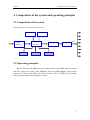
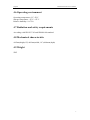
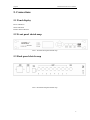
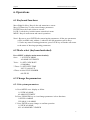
Gospell
GI-2850 SI inserter user’s manual
GI-2850
SI Inserter
User’s manual
1
Gospell
GI-2850 SI inserter user’s manual
Menu
1. Safety instruction ..........................................................................................................................3
2. Composition of the system and operating principle......................................................................4
2.1 Composition of the system..................................................................................................4
2.2 Operating principle .............................................................................................................4
3. Major features ...............................................................................................................................5
4. Technical specification..................................................................................................................6
4.1 Data input............................................................................................................................6
4.2 Data output..........................................................................................................................6
4.3 Network management interface ..........................................................................................6
4.4 Power off status preserving .................................................................................................6
4.5 Power supply.......................................................................................................................6
4.6 Operating environment........................................................................................................7
4.7 Radiation and safety requirements ......................................................................................7
4.8 Mechanical characteristic....................................................................................................7
4.9 Weight .................................................................................................................................7
5. Connections...................................................................................................................................8
5.1 Panel display .......................................................................................................................8
5.2 Front panel sketch map .......................................................................................................8
5.3 Back panel sketch map........................................................................................................8
6. Operations .....................................................................................................................................9
6.1 Keyboard functions .............................................................................................................9
6.2 Mode select (keyboard unlocked) .......................................................................................9
6.3 Change the parameters ........................................................................................................9
6.3.1 Set system parameters ..............................................................................................9
6.3.2 Set the parameters of the output TS .......................................................................10
6.3.3 Set the time and date ..............................................................................................10
6.3.4 Set the parameters of the files ................................................................................11
7. System errors and debugging......................................................................................................12
7.1 Indicator status ..................................................................................................................12
7.2 Trouble shooting ...............................................................................................................12
7.2.1 The “POWER” indicator light does not illuminate ................................................12
7.2.2 “STATUS” illuminates (in red ) .............................................................................12
7.2.3 “AlARM” flashes ...................................................................................................12
8. Network management .................................................................................................................13
2
Gospell
GI-2850 SI inserter user’s manual
1. Safety instruction
1.
2.
3.
4.
5.
6.
7.
8.
9.
Before starting using this unit, please be sure to refer to this manual.
Do not to open the cabinet, otherwise the guarantee to repair are not available.
Meanwhile touching the inside makes you in great danger of electric shock.
Please make sure to cut off the power supply if you will not use this unit in a long
term, and do not use any broken jack, which could result in fire or electric shock.
Wet hands are forbidden to touch the power jack, to avoid risk of electric shock.
Please pull the plug itself instead of the wire when you pull out power plug,.
Any thing flammable and metal or liquid, which will destroy the unit, must be
kept out of the box.
Do not place this unit in a location near a heat source such as radiator or air ducts,
or in a place exposed to direct sunlight, excessive dust, moisture, rain, mechanical
vibration.
Keep the device working in a good ventilative environment, if not the destruction
will occur.
Please keep the packaging for the safety of transit.
Attention: After setting all the parameters already, please press “lock”, after the LCD
darkles, that means locking succeed, then all the protective functions will
operate.
3
Gospell
GI-2850 SI inserter user’s manual
2. Composition of the system and operating principle
2.1 Composition of the system
The block diagram of composition of SI inserter:
FLASH
SDRAM
ARM
processor
RJ45
interface
LED
LCD
FPGA
CY7B923
ASI
Keyboard
2.2 Operating principles
By the Ethernet, the ARM processor communicates with NMS, take up control
and files, and save the files in the SDRAM. Then the ARM multiplex and circular
output the TS files to the FPGA, the FPGA sends the TS to CY7B923 by the setting
bit rate, then it achieves ASI interface’s output.
4
Gospell
GI-2850 SI inserter user’s manual
3. Major features
z
z
z
z
z
z
z
z
100M/10Mbps Ethernet self-adapting;
The total bit rate and the bit rate of each file can be set, which can automatically
inserts null packets;
The size of the TS packet can be set;
PID sequential counting value automatically updates;
Providing Chinese and English menu;
Supporting local and remote files’ operation;
Adopting LCD, which can locally monitor system status and setting parameter in
real time;
Power off memory.
5
Gospell
GI-2850 SI inserter user’s manual
4. Technical specification
4.1 Data input
Input interface: 1 DVB standard ASI interface
Connector: BNC
Impendence: 75Ω
TS standard: ISO013818-1
Valid input bit rate: max 214Mbps(Each channel)
TS packet format: 188/204bytes (automatically identify)
TS input model: equal/break out/irregular
4.2 Data output
Output interface: 8 DVB standard ASI interface
Connector: BNC
Impendence: 75Ω
Output TS standard: ISO013818-1
Valid output bit rate: 0.1Mbps~40Mbps adjustable (1Kbps step)
TS packet format: 188/204bytes compatible (There is no RS coding when in 204
bytes)
TS output model: equal
4.3 Network management interface
Ethernet interface: IEEE802.3ethernet, RJ45 interface
4.4 Power off status preserving
It can preserve the status of last time, when power resumes it can automatically
startup.
4.5 Power supply
Voltage: 90V~250V AC
Frequency: 50Hz±2%
Power: 25W
6
Gospell
GI-2850 SI inserter user’s manual
4.6 Operating environment
Operating temperature: 0°C~50°C
Storage temperature: -25°C~+55°C
Relative humidity: 10~75%
4.7 Radiation and safety requirements
According with GB13837-92 and GB8898-88 standard.
4.8 Mechanical characteristic
44.5mm(height,1U)×483mm(width, 19″)×400mm(depth)
4.9 Weight
5KG
7
Gospell
GI-2850 SI inserter user’s manual
5. Connections
5.1 Panel display
Power indication
Status indication
Failure alarm indication
5.2 Front panel sketch map
Inserter
PIC 1: GI-2850 front panel sketch map
5.3 Back panel sketch map
PIC 2: GI-2850 back panel sketch map
8
Gospell
GI-2850 SI inserter user’s manual
6. Operations
6.1 Keyboard functions
Move Right/Left key: Recycle the sub-menu/move cursor
Move Up/Down key: Locate cursor/change parameters
ENTER: Store the result /select to execute
LOCK: Lock the key /unlock/remote-control/exit menu
MENU: Recycle main menu and cancel operations
Note:1.Be sure to press ENTER after renewing the parameters, all the new parameters
will be available only without *, otherwise the old parameters still in keep.
2. Under any status of setting parameters, press LOCK key will make unit return
to the status of showing operating parameters.
6.2 Mode select (keyboard unlocked)
Press MENU to display main menu circularly
Once: 1.0 VIEW ALARMS
ALARMS LIST EMPTY
Twice: 2.0 SET CODE RATE
02.000Mbps
3 Times: 3.0 SET DATE TIME
2007-5-24 00:45:35
4 Times: 4.000.0 FILE NUMBER
008 FILES
6.3 Change the parameters
6.3.1 Set system parameters
A. Press MENU once: display as follow
1.0 VIEW ALARMS
ALARM LIST EMPTY
B. Press UP/DOWN key to view/change parameters /select functions
1.0VIEW ALARMS
CLEAR ALL ALARMS
C. Press ENTER to store change or confirm operation
1.0 VIEW ALARMS
ALL ALARMS BE CLEARED
9
Gospell
GI-2850 SI inserter user’s manual
D. Press LEFT/RIGHT to view sub-menu
1.1 SET IP ADDR.
120.120.120.160
1.2 SET NET MASK
255.255.255.000
1.3 NET GATE
120.120.120.001
1.4 NET STATUS
NOT CONNECTED or CONNECTED
1.5 SERIAL No.:
XXXXXXXXXXXXXXXXXX (18-digits)
1.6 VERSION
H: XX.XX
S: XX.XX
1.7 GET PRESET PARAMETER
*FACTORY PRESET
Press ENTER to store exchange.
1.8 SAVE NOW PARAMETER
*SAVE IN NAME01
Press ENTER to store the parameter
1.9 SELECT LANGUE
*ENGLISH
Press ENTER to select the corresponding language
E. In any status, pressing lock to exit
6.3.2 Set the parameters of the output TS
A. Press MENU twice: display as follow
2.0 SET CODE RATE
03.000Mb/s
B. Press LEFT/RIGHT to set TS packet format
2.1 SET PACKET SIZE
*188 Byte
C. Press UP/DOWN to change the bit rate
Pressing ENTER to confirm and store the result, pressing MENU to give up current
operation.
6.3.3 Set the time and date
A. Press MENU 3 times: display as follow
3.0 SET DATE TIME
2007-5-24 01:30:33
B. Press UP/DOWN to change the parameters
3.0 SET DATE TIME
10
Gospell
GI-2850 SI inserter user’s manual
*2007-5-24 01:30:33
Pressing ENTER to confirm and store the result, pressing MENU to give up current
operation.
6.3.4 Set the parameters of the files
A. Press MENU 4 times: display as follow
4.000.0 FILE NUMBER
008 FILES
B. Press LEFT/RIGHT to view or change the file attributes
4.000.1 USED MEM
254 KByte
4.000.2 VALID MEM
51,000 KByte
4.000.3 VALID RATE
02.100Mb/s
4.000.4 STREAM RATE
01.000Mb/s
4.000.5 STREAM (ON)
*ON
Pressing UP/DOWN to change the parameter, pressing ENTER to confirm and store
the result, pressing MENU to give up current operation.
C. Press UP/DOWN to view or change the files’ parameters
4.xxx.0 FILE NAME
Ttt.ts
4.xxx.1.FILE SIZE
1504 Byte
4.xxx.2 SEND (ON)
*OFF
4.xxx.3 SEND RATE
01.000Mb/s
Pressing UP/DOWN to change the parameter, pressing ENTER to confirm and store
the result, pressing MENU to give up current operation.
11
Gospell
GI-2850 SI inserter user’s manual
7. System errors and debugging
7.1 Indicator status
There are 3 LED indicators on the front panel, as follow:
1) “POWER” is the power supply indicator, when turn on the power, the indicator
turns red, that mean the power supply works normally.
2) “STATUS” if this indicator is green, that means the status of input signal is
normal.
3) “ALARM” if this indicator is green, that means the device works normally.
7.2 Trouble shooting
7.2.1 The “POWER” indicator light does not illuminate
Please check the wire to make sure the wire is connected to the socket properly and
the power switch is on.
7.2.2 “STATUS” illuminates (in red )
This means input signal is abnormal, please check the input data cable is connected
properly. Otherwise, it means the unit is broken, needs to be replaced.
7.2.3 “AlARM” flashes
This means the equipment is out of order for some faults. Please debug according to
the instruction from LCD.
12
Gospell
GI-2850 SI inserter user’s manual
8. Network management
The unit could be controlled remotely via network management software. It needs authorization.
Please refer to 《NMS user’s manual》
13