1
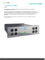
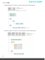
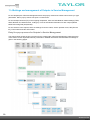
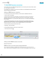
TAYLOR
Wisi UK Agent
SW version 2.0
Installation Guide
Rear View
1
Ta y l o r B r o s . ( O l d h a m ) L i m i t e d . T
Te
el : 0 1 6 1 6 5 2 3 2 2 1 , F a x : 0 1 6 1
626 1736
www
w.. t a y l o r b rro
os . c o . u k
TAYLOR
CHAMELEON
Single Hardware Headend
THE CHAMELEON PRODUCT LINE
COVERS ALMOST EVERY NEED
FOR CABLE-TV AND SMATV
DISTRIBUTION WITH ONLY ONE
HARDWARE..
The different inputs, processing
and outputs are defined by
software options, and all software
options can be updated at any
time.
The CHAMELEON includes a dual
DVB-S/S2/T/T2/C receiver,
furthermore it includes decoding of
MPEG-2 and MPEG-4 video formats
as well
as it supports MPEG, AAC HE and
Dolby audio decoding. The Dolby
audio decoding requires the latest HW
version.
The SW options define the different
“product realisations” you can
implement with the unique HW. For
your specific application, you simply
buy the SW options you need. When
you need further functionality, just
purchase additional SW options, and
update the installed HW.
CHAMELEON Product examples
■ Receiver DVB-S/S2/T(T2)/C
■ Transmodulators
■ DVB-C, DVB-T modulators
■ DTMB modulator
■ Analog VSB RF-modulators
■ FM modulator
■ Edge QAM/COFDM
■ Dual MPEG2/4 SD decoder
■ Single MPEG2/4 HD decoder
■ CI multi-decryptions
■ Remultiplexer multiple TS
■ DVB_CSA Scrambler
■ IP streamer
■ ASI streamer
■ SDI generator
2
©WISI Communications 2014, Subject to technical changes and misprints
TAYLOR
Support
For support information and help, please contact our s
upport organisations. Taylor in Oldham
[email protected]
Telephone:
0161484 3100
3
©WISI Communications 2014, Subject to technical changes and misprints
1 Getting started
TAYLOR
Your Chameleon Unit comes pre configured as your order so all you have to do is set the
RF frequency and v ideo settings if required
4Communications 2014, Subject to technical changes and misprints
©WISI
TAYLOR
5
©WISI Communications 2014, Subject to technical changes and misprints
3 Chameleon in GN50
TAYLOR
NOTE!
For Chameleon running FW2.0 and installed in a GN50, please make sure that the GN50/GT11
FW is upgraded to SW version 2.0.
Most of the functionality of FW2.0 will be possible to access while running FW1.1.1 in GN50, but
new functionality added in FW2.0 for Chameleon, such as IP VBR input to digital output is only possible
to manage via the System UI if the GN50 is upgraded to SW2.0. Functionalities not supported via the
System UI can still be managed when connected directly to the management IP address of the
Chameleon.
For more information about this SW version for GN50, and for access to the SW2.0 file, please
refer to documents .
6
©WISI Communications 2014, Subject to technical changes and misprints
TAYLOR
7 Connecting to the CHAMELEON user interface
Default IP address: 192.168.0.20
The default IP address for a CHAMELEON module is 192.168.0.20. Change the IP address to a
unique IP address in your network, in the web UI under Settings / Networking, or by using the
IP-Supporter.
Connecting with web browser
Use a standard web browser on your computer to connect by typing the IP address of the
CHAMELEON in the address field.
Supported web browsers
The CHAMELEON web interface is verified for Firefox version 14 and Internet Explorer 9. Other
browsers might work, but the functionality cannot be guaranteed.
General information about the web interface structure
The web UI is designed to get a logical structure for the user/installer, and an overview of the
module via the top tabs.
Operation mode must be selected before starting to
use the CHAMELEON. The selected Operation mode
will have implications on the general functionality of
the module, e.g. the possible output standard and
the IP streaming capability. The main interface while
managing services is the Service Management.
Here, you will have an overview of the configured
inputs and outputs, and you will also manage the
service selection, remultiplexing and decryption.
Before you start managing the services, you should
add and configure the inputs and the outputs in
their respective tabs.
The Settings tab contains module settings such as Networking, Headend System Management,
Operation Mode, Common Interface, SW and Entitlement Upgrade, Maintenance, and Log. The
CAM menu, if available, is also displayed in the Common Interface menu under the Settings tab.
7
©WISI Communications 2014, Subject to technical changes and misprints
8 Select operation mode
TAYLOR
Your equipment comes pre configured additional functions listed below
can be added ,contact [email protected]
Mode selection implications
The selected operation mode will have an impact on the possible selection of output.
■ Analog mode: for 1 or 2 analog RF and/or SDI output.
■ DVB-T mode: for 1 or 2 digital terrestrial modulation (COFDM).
■ DVB-C mode: for digital cable TV modulation (QAM), 1 to 4 DVB-C multiplexes.
■ J.83 Annex B mode: for digital cable TV modulation (J.83 Annex B), 1 or 2 J.83 Annex B
multiplexes.
■ J.83 Annex C mode: for digital cable TV modulation (J.83 Annex C), 1 to 4 J.83 Annex C
multiplexes.
■ Streaming mode: for IP-TV output (TS over IP). Up to 20 IPTS out.
■ FM mode: for up to 8 analog FM outputs.
■ DTMB mode: for 1 DTMB out
8
TAYLOR
For all the different operation modes, your CHAMELEON module must also be equipped with the
appropriate SW options, see more details in §15.
ASI and IP for all operation modes
In all operation modes, input and/or output via ASI is available simultaneously. The ASI in/out can
be used simultaneously with the modulated and IPTS outputs. The different operation modes also
have capability for simultaneous IPTS (SPTS and/or MPTS) inputs and outputs. The number of IPTS
in different operation modes are given to the right.
Number of IPTS1) in/out in
different operation modes
■ Analog: 2 IPTS in / 4 IPTS out
■ DVB-T: 20 IPTS in / 4 IPTS out
■ DVB-C: 20 IPTS in / 6 IPTS out
■ J.83B: 20 IPTS in / 4 IPTS out
■ J.83C: 20 IPTS in / 6 IPTS out
■ Streaming: 4 IPTS in / 20 IPTS out
■ FM: 8 IPTS in / 2 IPTS out
■ DTMB: 10 IPTS in / 2 IPTS out
1) IPTS
= SPTS and/or MPTS
9
©WISI Communications 2014, Subject to technical changes and misprints
TAYLOR
9 Add and configure inputs
Go to Inputs
Click on the Inputs tab. Depending on the SW options in your CHAMELEON, you can configure
inputs from:
■ Tuner (up to 2 tuner inputs, note that available inputs depends on HW version)
■ ASI (up to 2 ASI inputs)
■ IP (up to 20 IPTS inputs, depending on Operation Mode)
Add an input
1. Click on ADD NEW INPUT to expand the input creation menu.
2. Select input type in the Choose input type drop-down list (ASI, DVB-C, DVB-S, DVB-S2,
DVB-T, DVB-T2, IPTV. Selectable tuner inputs will depend on the tuner installed).
3. Enter the settings, and confirm/save by clicking the “green tick”
Configure the input
For each type of input, you will get configuration settings in the expanded view.
1. Type a name for the input. This name will be shown in the overview of the inputs.
2. Fill out the required information/parameters and click Save.
Input status
If your settings were OK, the status will show you basic information and no error indication.
If your settings were not OK, a red exclamation mark
give indication about the art of the error.
10
will indicate an error, and the mouse-over will
9.1 Add ASI and IP inputs
TAYLOR
Adding ASI inputs
Go to Inputs, and click on ADD NEW INPUT. Select ASI in the drop down
list for Input type. Type a name for your ASI input. Select the Physical port
from the drop down list. Port 1 is the top BNC 1 connector, port 2 is the lower BNC
2 connector. Click the “green tick”
to save the settings.
ASI inputs automatically
detects the incoming bit rate.
Add IP inputs
Go to Inputs, click ADD NEW INPUT. Select IPTV in the drop down list for Input
type list. Type a name for your new IPTV input. Select Bitrate mode:
■ CBR Automatic (auto-detects the incoming constant bit rate)
■ CBR Manual (manual setting of constant bit rate in)
■ VBR (Variable bit rate in)
Select Network interface. If no network interface is available,
you can use the link Manage interfaces. More information
about Network Interfaces are given in §13.1
Select Routing scheme, Multicast or Unicast:
■ For Multicast; enter the Multicast address and Port
■ For Unicast: enter the Port (address will be the same as the IP address of the streaming interface)
Click the “green tick”
to save the settings.
Input status and edit settings
If your settings were OK, the status will not indicate any error. Expand the input by clicking the
in
front of the input name to see further information. Click the
in front of Settings to edit settings.
11
©WISI Communications 2014, Subject to technical changes and misprints
TAYLOR
9.2 Add tuner inputs
Adding tuner inputs
The available tuner input types
will depend on the SW
options, and on your HW.
1. Go to Inputs and click on ADD NEW INPUT .
2. Select the tuner type in the Input type list.
3. Type a name for your input.
4. Select the Physical port from the drop down list. Port 1 is the top F-connector (RF in 1), port
2 is the lower F-connector (RF in 2), see picture in §9.1.
5. Fill out the required settings and click the “green tick”
to save the settings.
Note that each input type has its own set of input settings. Below some examples.
Example of terrestrial input settings
Example of satellite input settings
Example of cable TV input settings
Input status and edit settings
in
If your settings were OK, the status will not indicate any error. Expand the input by clicking the
front of the input name to see further information. Click the
in front of Settings to edit settings.
12
©WISI Communications 2014, Subject to technical changes and misprints
TAYLOR
10 Add and configure outputs
Go to OUTPUTS
Depending on SW options, and Operation mode, you can configure up to:
■ 2 Analogue RF out (PAL, SECAM)
■ 8 analogue FM radio
■ 2 SDI out
ASI in/out and SDI shares the
2 BNC ports. These ports are
controlled by software
settings.
■ 2 ASI out
■ 2 DVB-T out
■ 4 DVB-C out
■ 2 J.83 Annex B out
■ 4 J.83 Annex C out
■ 1 DTMB out
■ 20 IPTS out
Add and configure an output
In the Outputs tab, click ADD NEW OUTPUT.
1. Select output type (ASI, SDI, IPTV, DVB-C, J.83 Annex B, J.83 Annex C, DVB-T, ANALOG,
FM, DTMB) from the drop-down list. The available selection depends on Operation mode and SW
options.
For each type, you will get different configuration settings in the expanded view.
2. Fill out the required information/parameters
3. Click the “green tick”
to save the settings.
Output status
After saving, the status of the configured outputs is shown. If e.g. too
many outputs are configured, or an output that is not supported in
the current Operation mode, there will be an error message displayed.
13
©WISI Communications 2014, Subject to technical changes and misprints
TAYLOR
10.1 Add and configure analogue (PAL, SECAM) outputs
Adding analogue output
Select Analog mode as Operation Mode, see also §8.
1. In the Output, select Analog in the Output type list
2. Type a name for the output
Decoder settings
1. Select decoder instance (there are 2 decoder instances available)
2. Select the service in the Services drop down list. Note: if the incoming service is encrypted,
you have to select the input to the CAM in Settings / Common Interface, and select to
descramble the service in the Service Management. In the Services drop down list, make
sure to select the decrypted service.
3. Select PAL or SECAM video standard in the Video standard drop down list
4. Select audio language (Optional. If only 1 audio language is transmitted use “Default”)
Subtitling settings
1. Select Subtitling ON
2. Select subtitling language from the drop down list, or enter the 3 letter language code according to ISO
639-2.
3. Select Subtitle priority, Subtitle type, Teletext codepage, and optionally Subtitle conversion and WSS
subtitle configuration
14
©WISI Communications 2014, Subject to technical changes and misprints
TAYLOR
Modulator settings
1. Select TV standard, Audio system and Frequency table from the drop-down lists
2. Enter an output frequency, or select a channel from the drop down list.
3. Enter an output carrier level
Save settings
Click the “green tick”
to save the settings.
Advanced settings
To get access to the advanced settings, click the
in front of the Advanced settings.
Language selection for audio language and subtitling
For audio language, you can use default language, select the language from the drop down list, or
manually enter the 3 letter language code according to ISO 639-2. When you use the manual settings,
you can find the PID number in the Service Management, on the input side, when expanding to service
level.
For subtitle language, you can select language from
Dolby audio decoding
requires hardware revision
the drop down list, or enter the ISO 639-2 code.
1402 or higher, and the
GNDOL SW option.
Important information about HD to SD downscaling
The MPEG decoder can downscale one service from MPEG2/4 HD to SD. When using the MPEG
decoder for downscaling, you are limited to 1 analogue output.
www.wisi.de
Dual mono output
It is possible to set up one analogue output with dual mono sound (different languages in left/right audio
channel).
1. Create 2 analogue outputs
2. Set up both decoders with the same service but different audio languages
3. Select Stereo mode: Dual mono (Decoder settings)
4. Deactivate the second analogue output (Output enabled = OFF)
5. In the Modulator settings, select Audio system A2 Dual mono or NICAM Dual mono
6. Select Dual mono source: Both decoders
15
©WISI Communications 2014, Subject to technical changes and misprints
TAYLOR
10.2 Add and configure ASI, SDI and FM outputs
Add ASI outputs
1. In the Output, select ASI in the drop down
list for Output Type
2. Enter name, physical port and bitrate
3. Click the “green tick”
to save the settings.
Add and configure SDI outputs
Select Analog Operation Mode
1. In the Output, select SDI in the Output Type list
2. Select the service in the Services drop down
list
3. Set the audio language and subtitle settings
4. Optionally, select Audio language
5. Click the “green tick”
to save the settings.
See also §10.1 for more information
about these settings.
Add FM radio outputs
Select FM mode as Operation Mode
1. In the Output, select FM in the drop down list for Output Type
2. Select the service in the Services drop down list
3. Enter Channel frequency and Carrier level
4. Optional: for RDS signalling, select the PI, PS and PTY sources, and enter the values if using
manual settings.
5. Click the “green tick”
to save the settings.
16
©WISI Communications 2014, Subject to technical changes and misprints
TAYLOR
10.3 Add and configure DVB-T, DVB-C, J.83 ANNEX B, J.83 ANNEX C
and DTMB outputs
Add DVB-T outputs
Select Operation mode DVB-T under Settings
1. In the Output, select DVB-T in the Output Type list
2. Enter a name for the output
3. Select Frequency table (CCIR or OIRT)
4. Select output channel, or set the output frequency in MHz
5. Select output bandwidth (5, 6, 7 or 8 MHz)
6. Set the output carrier level
Click the “green tick”
to save the settings.
7. Select the Forward error correction (FEC), the Guard interval
(GI), the Carrier mode and the Constellation from the dropdown lists
8. Click the “green tick”
Channel bonding. All output
muxes within 40 MHz band
(5 channels @ 8 MHz)
to save the settings.
Add additional DVB-T outputs
Repeat the steps above.
The Output Enabled ON/OFF gives you the possibility to configure an output without adding it
to your network. With Output enabled set to OFF, no signals will be transmitted.
Add DTMB output
Select Operation mode DTMB under Settings
1. In the Output, select DTMB in the Output Type list
2. Enter a name for the output
3. Select Frequency table (CCIR or OIRT)
4. Select output channel, or set the output frequency in MHz
5. Set the output carrier level
6. Select the Header length in the drop down list
7. Select the Interleaving length in the drop down list
8. Select the Constellation in the drop down list
9. Click the “green tick”
to save the settings.
17
©WISI Communications 2014, Subject to technical changes and misprints
23
Add DVB-C outputs
Select Operation mode DVB-C under Settings
1. In the Output, select DVB-C in the drop down list
for Output Type
2. Enter a name for the output
3. Select Frequency table (CCIR or OIRT)
4. Select output channel, or set the output frequency in MHz
5. Select Constellation in the drop-down list
6. Select QAM spectrum (Normal or Inverted)
7. Set the symbol rate
8. Set the output carrier level
9. Click the “green tick”
Channel bonding. All output
muxes within 40 MHz band
(5 channels @ 8 MHz)
to save the settings.
Add J.83 Annex B outputs
Select Operation mode J.83 Annex B under Settings
1. In the Output, select J.83 Annex B in the Output Type list
2. Enter a name for the output
3. Select Frequency table (CCIR or OIRT)
4. Select the output channel, or set the output frequency in MHz
5. Select Constellation in the drop-down list
6. Select interleaving mode in the drop-down list
7. Select QAM spectrum (Normal or Inverted)
8. Set the output carrier level
9. Click the “green tick”
to save the settings.
Channel bonding. All output
muxes within 40 MHz band
(5 channels @ 8 MHz)
Add J.83 Annex C outputs
Select Operation mode J.83 Annex C under Settings
1. In the Output, select J.83 Annex C in the Output Type list
2. Enter a name for the output
3. Select Frequency table (CCIR or OIRT)
4. Select the output channel, or set the output frequency in MHz
5. Select Constellation in the drop-down list
6. Select QAM spectrum (Normal or Inverted)
7. Set the symbol rate
8. Set the output carrier level
9. Click the “green tick”
to save the settings.
Channel bonding. All output
muxes within 40 MHz band
(5 channels @ 8 MHz)
Add additional DVB-C, J.83 Annex B or J.83 Annex C outputs
Repeat the steps above.
18
©WISI Communications 2014, Subject to technical changes and misprints
www.wisi.de
24
10.4 Add and configure IP (SPTS/MPTS) outputs
Configure a network interface for streaming (see also 12.1)
1. Go to Networking in the Settings tab, and select Add interface.
– For GN01 or GN40 mounting, add a new network interface for the streaming port.
– For GN50 mounting, add a new network interface to the backplane port.
2. Enter name for the interface, and IP parameters
3. Select Streaming ON, and click the “green tick”
to save the settings
Add IPTV outputs
1. In the Output, select IPTV in the drop down list for Choose output type
2. Select protocol, UDP or RTP
3. Select the bit rate mode, CBR or VBR
4. Set the output bit rate
5. Set the TTL (Time to live). The default TTL=255 => no limit for the lifespan of data.
6. Select Network interface
7. Set the destination (streaming) address and port.
8. Click the “green tick”
to save the settings
Multicast vs. Unicast
Multicast or Unicast transmission is selected automatically by the address range used. In IPv4,
addresses 224.0.0.0 through 239.255.255.255 are designated as multicast addresses.
19
©WISI Communications 2014, Subject to technical changes and misprints
www.wisi.de
TAYLOR
11 SERVICE MANAGEMENT, service & PID management
Service Management functionality and pre-requisites
The Service Management tab is the main view for handling remultiplexing, service selection,
decryption, encryption and PID management. Before using the Service Management for
management of services and PIDs, the inputs and outputs of the CHAMELEON module must be
configured, see §9 and §10.
Service Management - left part for Inputs, right
part for Outputs
Note that the Input and Output parts of
Service Management can be collapsed/
expanded by clicking on the expand/
collapse icon at the top right:
The Service Management menu has 2 main parts. In the left
part, information about inputs (Inputs, Services) are shown. The
right part contains information about the outputs (Outputs, Services). You can select to show
information about Inputs/Outputs or Services by clicking the tabs at the top of the 2 main views.
■ In the Inputs view, the listing is based on the configured inputs in the CHAMELEON,
see §11.1
■ In the Outputs view, the listing is based on the configured outputs in the CHAMELEON,
see §11.1
■ The Services views list all incoming/outgoing services, see §11.2
Information about inputs/outputs, services and PIDs can be accessed in any view, and the view
you select to work with will depend on what you want to check or configure.
Service Management navigation
To navigate (expand/collapse) menu entries, the arrows in front of a menu is used:
■ Click the
icon to expand a menu and show the sub-menus
■ Click the
icon to collapse a menu and hide the sub-menus
Menu list sorting
All listings can be sorted according to any column name. Click a column name to sort the list
entries by this column
. Click again to sort in reversed order
.
20
©WISI Communications 2014, Subject to technical changes and misprints
TAYLOR
11.1 Navigating the In/Outputs view in Service Management
In the Inputs and Outputs views in Service Management, all inputs and outputs for the
CHAMELEON are listed. The top entries in the navigation trees are the physical inputs and outputs
configured. To navigate in the menus, use the
and
arrows to expand/collapse. The
complete navigation graphs for these views are given in the next 2 pages.
Note that each entry in the lists has additional information via “mouse over” or hover that is
displayed when you place the mouse pointer over an entry. The hover pop-up gives you information
about the input or output name, and which module that the input or output is configured in.
To add a service to an output, navigate to the Service level, click the
and select the output to
add the service to. More information about the managing services and PIDs in the System
Management is given in §11.4 and §11.5.
21
©WISI Communications 2014, Subject to technical changes and misprints
www.wis.de
TAYLOR
Navigation graph for the Inputs view for Inputs in Service Management
22
©WISI Communications 2014, Subject to technical changes and misprints
TAYLOR
www.wisi.de
Navigation graph for the Outputs view for Outputs in Service Management
23
©WISI Communications 2014, Subject to technical changes and misprints
TAYLOR
11.2 Navigating in the Services view in Service Management
In the Services views in Service Management, all services in and out for the CHAMELEON are
listed. The top entries in the navigation trees are the services from the configured inputs and
outputs. To navigate in the menus, use the
and
arrows to expand/collapse. The complete
navigation graphs for these views are given in the next page.
Each entry in the lists of services have additional hover information when you place the mouse
pointer over an entry. The hover pop-up states which module the service is coming from, the
name of the input/output and (for output) the name of the input.
Inputs hover:
Outputs hover:
To add a service to an output, click the
tailing a service on the input side, and select the output
to add the service to. More information about the managing services and PIDs in the System
Management is given in §11.4 and §11.5.
24
©WISI Communications 2014, Subject to technical changes and misprints
TAYLOR
Navigation graph for the Services view for Inputs in Service Management
Navigation graph for the Services view for Outputs in Service Management
25
©WISI Communications 2014, Subject to technical changes and misprints
TAYLOR
11.3 Managing services and PIDs in the Inputs part of Service
Management
Management of services, PIDs etc. in the Service Management is handled via pop-up menus.
The presence of a pop-up menu is indicated by a grey arrow,
, at the end of an entry line.
For the input services, the menus are used to select services to the outputs. For inputs from CI,
descrambling of services or PIDs are also managed., see §11.6.
Entry line pop-up menus for Inputs in Service Management
The picture below shows the pop-up menus for the Inputs side of Service Management. Note that
many of the entries contain important read-only information.
Detailed information about the different actions you can do in the pop-up menus are given in the
following pages.
26
©WISI Communications 2014, Subject to technical changes and misprints
TAYLOR
www.wisi.de
Managing services, PIDs and descrambling in Inputs in Service Management
Selection of services from inputs to outputs and descrambling of services or PIDs is managed via
the pop-up menus indicated by a grey menu arrow,
, tailing the different menu line entries. If
no menu arrow is present, the information is read-only.
Input level pop-up menu
The pop-up menu at Input level allows you to add all services of an input
to an output, or to connect an input transparently to an output. The
Character encoding menu allows you select the encoding standard
for the service names and for the provider names, see §11.4.2.
Add all services
Click on Add all services to, and select the output to add the services to.
This will result in the same as adding all services one by one on the Service level, and the automatic
remultiplexing including creating correct PSI/SI will be done.
Connect transparently to
When you select Connect transparently to, all services of an input will be added to the selected
output, and no change is done in the PSI/SI information. An output that is connected transparently
to an input is marked with the
icon.
Service level pop-up menu
The pop-up menu at Service level allows you to add services one by
one to an output by clicking Add and selecting the output in the new
pop-up menu.
The Descramble command sets all PIDs to be descrambled. This
command is only available for CI inputs. For more information about descrambling, see §11.6.
Stream level pop-up menu
The pop-up menu at Stream level allows you to descramble individual PIDs of
a service. This menu is only available for CI inputs. The Descramble command
on Stream level is activated only if the service is descrambled on Service level.
The Add to output and Add to service commands are covered in §11.3.1.
When selecting to descramble a PID, all
other PIDs will become not selected for
descrambling. Hence, if you need to
descramble on PID level, make sure
that you select descramble for all PIDs
that you want to descramble.
27
©WISI Communications 2014, Subject to technical changes and misprints
TAYLOR
11.3.1 Advanced management of tables and streams in Inputs
The Service Management in FW2.0 includes advanced management of tables (PSI/SI tables) and
streams (ranging from EMM and ECM streams to elementary streams such as audio streams or video
streams). This enables a wide range of advanced applications, where the user is assumed to have
thorough knowledge of how to manage the tables and streams.
Please note that using this functionality also adds the possibility to create
configurations that will not be according to standard application, and
hence potentially can create problems in a network. It is advised to
contact Support if there are any doubts about correct settings or
applications.
Please contact Support if you
are unsure about how to use
the Advanced settings.
Pop-up menus for advanced applications
All menu entries below Service level at the Inputs part of Service
Management have pop-up menus allowing you to add the entry to an
output, or to a service of an output.
The presence of a pop-up menu is indicated by a grey arrow,
end of an entry line.
, at the
Advanced application example
This user manual will not cover all settings and applications for the
advanced settings. As one example of possible usage of the advanced
settings, you can add incoming unreferenced streams (“PIDs”) to an
output, or to a service in an output. This can be used e.g. for adding
OTA data or EPG (EIT) from external sources.
For specific use cases, please contact Support for help or further
documentation.
28
©WISI Communications 2014, Subject to technical changes and misprints
www.wisi.de
TAYLOR
11.4 Settings and management of Outputs in Service Management
For the Outputs part of Service Management there are pop-up menus and context menus where you type
parameters. Edit in pop-up menus can open a context menu.
For the transport streams (TS) in the outgoing multiplexes, there are DVB Network related settings (TSID,
ONID, Network ID, Network name, LCN type). There is also bitrate information for each output (utilized
bitrate and configured (limit) bitrate).
For the services in the outputs, there are settings for service name, service provider name, SID (Service
ID), LCN number and HD LCN number.
Entry line pop-up menus for Outputs in Service Management
The picture below shows the pop-up menus for the outputs side of Service Management. Note that many
of the entries contain important read-only information. Detailed information about the different settings is
given in the following pages.
29
©WISI Communications 2014, Subject to technical changes and misprints
www.wisi.de
TAYLOR
Managing output settings, service settings and PIDs
Removing services, edit output TS settings (TSID, ONID, Network ID, Network name, LCN type), edit
service settings (service name, service provider name, SID, LCN and HD LCN number), and edit stream
settings (IN PID number, OUT PID number, block/unblock, set stream type) is managed via the menus in
the Output side of Service Management.
Connecting outputs to EMMg and services to SCG is managed in the Outputs of Service Management.
Elementary stream level scrambling is also managed in these menus. The scrambling related settings
will be covered in §12.
Output level pop-up menu (remuxed)
The pop-up menu at Output level allows you to edit the main TS DVB
Network settings, remove all services from an output, add an EMM
connection (see §12), and set the Character encoding (see §11.4.2).
Output level pop-up menu (transparently connected)
The pop-up menu at Output level of an output that is transparently connected from an input allows
you to disconnect the transparent connection or edit the Network ID (NID). Note that editing the
NID is possible only if you have selected Share NIT to ON under Setting.
Note: there are 2 different ways to edit the DVB
Network settings for an output:
■ Select Edit in the Output level pop-up menu
■ Navigate to the Settings under an output, and select Edit for this
menu, see the following page
These 2 menus have different layout, but contain the same
information, except that the Network name entry is not available from
the Output level pop-up Edit.
Output / Setting level pop-up menu
The Edit in the pop-up at Output / Setting enters the menu for the
DVB Network settings for TSID
(Transport Stream ID), ONID (Original Network ID), Network ID,
Network name and LCN type. See more information about the DVB
Network settings in §11.9.
Output / PSI/SI tables level menu
Expanding the PSI/SI tables entry lists the tables, and for each table or sub-table there is a pop-up menu
allowing you to Edit or Reset. These menus are generally intended for advanced settings, and will be
covered in §11.4.1.
Output Service level pop-up menu
The pop-up at Service level allows you to edit the service settings (service name, service
provider name, SID, LCN and HD LCN number). The Revert changes will reset all service
settings to the original values. Remove will remove this service from the output. Connect
to / Disconnect from SCG (for scrambling) is described in §12. The Character encoding
menu allows you select the encoding standard for the service names and for the provider
names, see §11.4.2.
30
©WISI Communications 2014, Subject to technical changes and misprints
TAYLOR
Output Stream level pop-up menu
The pop-up at stream level allows you to edit the Out PID value, set the stream type, block (or
unblock) the stream in the output and scramble the stream. Scrambling is described in §12.
11.4.1 Advanced management of tables and streams in Outputs
The Service Management in FW2.0 includes advanced management of tables (PSI/SI tables) and
streams (ranging from EMM and ECM streams to elementary streams such as audio streams or video
streams). This enables a wide range of advanced applications, where the user is assumed to have
thorough knowledge of how to manage the tables and streams.
Please note that using this functionality also adds the possibility to create
configurations that will not be according to standard application, and
hence potentially can create problems in a network. It is advised to
contact Support if there are any doubts about correct settings or
applications.
Please contact Support if you
are unsure about how to use
the Advanced settings.
Advanced application example
This user manual will not cover all settings and applications for
the advanced settings. As one example of possible usage of the
advanced settings, you can create a service in an output without
adding a service from the Input part of Service Management.
For specific use cases, please contact Support for help or further
documentation.
PSI/SI table management
All PSI/SI tables are listed under the PSI/SI table entry, and can
be displayed by clicking the arrow
in front of the entry line.
The general pop-up menu is allows you to edit the table settings
(enabled On / OFF, table repetition rate), or reset to the default
values. For most tables, you can also create descriptors and/or
block incoming descriptors.
As an example of PSI/SI table management, all the EIT Actual
Schedule and EIT Other Schedule tables can be enabled or disabled, allowing you to modify the “EPG”
data transmitted.
For specific use cases, please contact Support for help or further documentation.
31
©WISI Communications 2014, Subject to technical changes and misprints
TAYLOR
11.4.2 Character encoding
DVB specifies a number of standard encodings of text strings, e.g. Service Names and Service Provider
Names. These include ISO 8859-1 ISO 8859-15, GB-2312, BIG5, and UTF8. To indicate the encoding
used, there is a flag in the SDT. If there is no flag, the name decoding should use ISO 6937.
Some transmissions omit the flag, but choose not to encode in ISO 6937. You may also want to use an
encoding that is not defined by DVB.
Character encoding settings for inputs
On the input side of Service Management, there are settings for text
encoding for the Service Name and the Service Provider Name. These
settings can be used if there is no encoding flag in the incoming SDT.
Character encoding settings for outputs
This setting only has effect
if the input service does NOT
have a flag for character
encoding.
At the output side of Service Management, there are encoding settings at output level as well as at
service level. A service will inherit the encoding of the output unless you have set a specific encoding
setting for the service.
For input services:
■ Selecting a character encoding only has effect if the incoming SDT is
without character encoding flag
For output services:
■ For a not changed service name, and the output encoding set to
Automatic (default), the service name is copied directly from the inputs
■ For a not changed service, and the output encoding set to anything other
than Automatic, the service name is decoded (according to the setting/flag
for inputs), and encoded with the selected output encoding
■ For a changed service/service provider name, and the output encoding set
to Automatic, the CHAMELEON tries to encode the configured service name
in an encoding that fits the text, e.g. “abcd” is encoded with ISO 6937 while
“åäö” encoded with ISO 8859-9
■ If the service/service provider name is changed and the output encoding is
set to anything other than Automatic, the name will be encoded with the set
encoding.
In all cases except the first, for “No DVB signalling” the encoding used is
removed.
32
©WISI Communications 2014, Subject to technical changes and misprints
11.5 Descrambling and Common Interface
TAYLOR
11.5.1 Common Interface and CAM/smart card
Descrambling requires a CAM to be inserted in one of the CI slots, and a smart card with the
rights for descrambling the services. Note that multi-descrambling using professional CAMs is
supported. CI settings are managed in the COMMON INTERFACE menu under SETTINGS.
Insert the CAM and smart card in the CI slot
Insert the CAM and smart card into the correct CI slot. From a rear view,
CI slot 1 is to the left, CI slot 2 to the right.
Make sure that CAM is
inserted with text side to
the right
Select CI source – set which input to be connected to the CI slot
In the COMMON INTERFACE menu, Click Edit. Type a name for the CI. This name
will appear in the Service Management as a input with type CI.
In the drop-down list of Select CI source, select the input to be connected to this common interface
slot. The Bitrate selection in the drop-down list (72 Mbps, 62 Mbps, 55 Mbps) can normally be left
at the default value 72 Mbps for all modern CAMs.
11.5.2 Descrambling – Service level & PID level
After selecting CI source in the COMMON INTERFACE menu, a new “input” of type CI will be
displayed in the Inputs part of Service Management.
Select the services to be descrambled
Click the edit arrow
of the service you want to
descramble, and select Descramble in the popup menu.
To output a descrambled service, add the service from CI
input to an output (see §11.4).
33
©WISI Communications 2014, Subject to technical changes and misprints
TAYLOR
Descrambling status indication icons
PID level descrambling
At the PID level in the Inputs of Service Management, click the
edit arrow of the PID you want to descramble, and select
Descramble in the popup menu.
NOTE: When selecting to descramble a PID, all other PIDs will
by default be selected not to be descrambled. Hence, if you
descramble on PID level, make sure that you select to
descramble all
PIDS that you want to descramble.
Descrambling for analogue output
In Operation mode Analog you have to use the SERVICE MANAGEMENT for handling the decryption.
The analogue output service selection is made in the output menu, and when a CI source has been set,
the list of available services for analogue output will include the services routed via the CAM.
11.6 Remultiplexing and PSI/SI
Remultiplexing
In a CHAMELEON, remultiplexing is automatically done as services are selected from the inputs to
the outputs. As such, all remultiplexing is managed in SERVICE MANAGEMENT.
PSI/SI Management
The PSI/SI of the outputs are automatically generated as services
are assigned to the outputs. Selecting services from a single
input, or selecting services from several inputs both result in the
updating of the PSI/SI tables of the outputs.
34
©WISI Communications 2014, Subject to technical changes and misprints
DVB-Network PSI/SI Management
TAYLOR
To create a DVB-network-wide correct PSI/SI structure, all CHAMELEONS in the same DVB network
must be able to share PSI/SI information. The interconnection between the CHAMELEONS is
enabled by the HEADEND SYSTEM MANAGEMENT functionality, see §11.10.
Further, the GNSYMUX SW option must be active to allow the interchange.
11.7 Service listings and service types
Input service listings
The services of an input transport stream (TS) or an output TS can be
listed by navigating to the service level, see §11.1.
In the Inputs view of Service Management, expand an input, and
expand Services to get a list of all services from this input.
To view a list of input services from all configured inputs, click on the
Services tab to the right of the input side of Service Management.
Service listing information and types
The services in the input service listings have information columns
SERVICE (service name), SID (service_id), TYPE (service type) and
STATUS (indicating scrambling status).
The TYPE is indicated by icons (and also has mouse-over textual
information):
Output service listings
The services of an input transport stream (TS) or an output TS can be listed by navigating to the
service level, see §11.1.
In the Outputs view of Service Management, expand an output, and expand Services to get a list
of all services from this output.
To view a list of output services from all configured outputs, click on the Services tab to the right
of the output side of Service Management.
35
©WISI Communications 2014, Subject to technical changes and misprints
TAYLOR
Output service listing and information
The services in the output service listings have
information columns SERVICE (service name),
PROVIDER (service provider name), SID (service_id),
LCN (logical channel number) and HD LCD.
11.8 PIDs and PID listings
PIDs and PID listings and PID types
The PIDs of an input transport stream (TS) or an output TS can be
listed by navigating to the PID level, see §11.1. In the Inputs view of
Service Management, all PIDs including PSI/SI PIDs, EMM PIDs and
unreferenced PIDs are listed.
The Outputs view lists the audio PIDs, video PIDs, teletext PIDs and
data PIDs related to the services.
In the Services views of the Service Management, the service PIDs
(audio PIDs, video PIDs, teletext PIDs and data/unknown PIDs) are listed.
PID types and PID information
All PID listings have (at least) 3 columns:
■ PID number
■ PID type
■ Bitrate
PSI/SI PID types are given as table acronyms such as PAT, CAT NIT.
Service PID types are indicated with icons:
For outputs, the incoming as well as the outgoing PID
number is listed in the columns IN and OUT. Often the
outgoing PID number is the same as the incoming PID
number, but if the PID number already exists in the system,
there is an automatic PID remapping to avoid PID clashes.
Just as for the PIDs of the input services, the stream (PID)
types are indicated with icons.
36
©WISI Communications 2014, Subject to technical changes and misprints
TAYLOR
11.9 Outputs TS DVB Network settings
TSID, ONID, NID, LCN type and
Network Name
Each outgoing TS has a set of identifiers: TSID
(transport stream ID), ONID (original network ID),
NID (network ID), LCN (logical channel numbering
type) and Network Name. All identifiers can be
edited by clicking the edit arrow
TSID
The transport_stream_id (TSID) is a 16-bit field which serves as a label for identification of this TS
from any other multiplex within the delivery system. Hence, the TSID has to be unique within a
DVB Network.
ONID and NID
The SI uses two labels related to the concept of a delivery system, namely
the network_id (NID) and the original_network_id (ONID). The latter is
intended to support the unique identification of a service, contained in a
TS, even if that TS has been transferred to another delivery system than
the delivery system where it originated.
If no network_id (NID) is set,
the outputs will not contain
any NIT.
Network Name
A string of characters that specify the name of the delivery system about which the NIT informs.
A change of the Network Name is propagated to all TS with the same NID.
LCN (LCN type)
The LCN type specifies which LCN implementation to use. For a DVBNetwork,
the LCN type should be the same for all outgoing muxes.
Available LCN types are Nordig, EACEM and ITC (Independent Television).
11.10 Outputs services settings
Service name, service provider name,
service ID and LCN number
Each service in an outgoing TS has a set of
identifiers: Service name, service provider name,
service ID (SID) and LCN number. These identifiers
are listed for all output services. All identifiers can
be edited by clicking the edit arrow
37
©WISI Communications 2014, Subject to technical changes and misprints
The LCN number is
edited in the settings
for each service.
TAYLOR
SID
The service ID is a 16-bit field which serves as a label to identify this service from any other service
within a transport stream (TS). Hence, the service ID is a unique identifier of a service within a TS.
Service name and service provider name
The service name and the service provider name is textual information used by the receivers to
display information about the services.
LCN (LCN number) and HD LCN number
The LCN number, which will be used by a receiver to make a channel list, is edited for each service
in each outgoing mux. For correct functionality, the LCN number must be unique for each service
within a DVB network. For managing automatic reconfiguration of channel lists depending on
receiver capability, the HD LCN can be used.
11.11 The System management and DVB Network PSI/SI
For creation of a network-wide correct PSI/SI structure in a DVB Network, information about PSI/
SI has to be shared between the CHAMELEON modules in the same network. The basis for such
a sharing is that the CHAMELEONS are connected via a switch, and that a communication is set
up between the CHAMELEONS. Additionally, all CHAMELEONS that are to share PSI/SI information
must have the SW option GNSYMUX.
Headend System management
Under SETTINGS, in the HEADEND SYSTEM MANAGEMENT menu, you can select CHAMELEONS
in the same local (layer 2) network to be members in the same group, a HE Group.
When clicking EDIT, all CHAMELEON in the local IP network will be listed by their serial number.
To add a CHAMELEON to a HE Group, click the green
in the list of Selectable units. Please
note that the settings done in one CHAMELEON will automatically update the headend System
Management settings also for all CHAMELEONS in the same group.
38
©WISI Communications 2014, Subject to technical changes and misprints
TAYLOR
DVB network and PSI/SI sharing – network settings
When setting up a system where PSI/SI information is shared, you must also select network
settings for all outgoing transport streams. The network_id (NID) must be identical for all outgoing
transport streams, and all the transport streams must have different Transport Stream ID (TSID),
see also §11.9.
11.12 Transmodulation and transparent outputs
Connect input to output transparently
An input can be sent transparently to an output by selecting “Connect
transparently to”. When an input is “connected” to an output, as
default there is no change of the content of the transport stream from
input to output:
■ All services, with all PIDs are sent from the input to the output
■ The PSI/SI tables are sent from input to output without any change or modification
Settings for transparent outputs
As an alternative to the default setting (no change of content or signalling) there are settings
available for sharing NIT, Network ID (NID), Network name and Delivery system descriptor. You can
also select to remove null packets from the output.
To edit these settings, click the
for Settings, and then click the tailing
39
©WISI Communications 2014, Subject to technical changes and misprints
and select Edit.
TAYLOR
12 Encryption – DVB-CSA scrambling and Simulcrypt
Conditional Access System (CAS) general information
A conditional access system generally consists of two main subsystems:
■ A scrambling subsystem that a) scrambles the signal to prevent non-subscribers from
receiving it and b) descrambles the signal at the subscribers’ receivers.
■ An access control subsystem that processes access control messages to determine whether
descrambling is to be performed.
A CHAMELEON used in this context contains a Control Word Generator (CWG) generating
Control Words (CW) for the scrambling (DVB-CSA). To enable de-scrambling at the receiver side,
the CW is transmitted in encrypted format as ECMs. The ECMs are created by the CAS, based on
the CW, and an Access Criteria (AC) supplied by the CAS.
The access control system is handled by EMMs. EMMs are received from the CAS, and included in
the outgoing transport streams.
40
©WISI Communications 2014, Subject to technical changes and misprints
TAYLOR
CAS vs. CHAMELEON interface structure
When setting up a CHAMELEON for scrambling, there are 2 main interconnections between the
CHAMELEON and the CAS to be established:
■ The connection for receiving EMMs from the CAS
■ The connection for transmitting CW/AC to the CAS, and receiving the ECMs
Apart from this, there are some parameters/identifiers that has to be set internally in the
CHAMELEON.
EMM communication req’s
■ CHAMELEON IP address for the IP interface
used for Simulcrypt, and port for receiving
the EMMs (EMM port) has to be given to
the CAS.
■ The Client ID has to be provided by the
CAS, and entered in the CHAMELEON UI
when setting up the connection.
The internal identifiers that has to be set in
the CHAMELEON UI is the EMMg name. The
EMM PID will be automatically assigned by the
Chameleon, and can be changed in Service
Management.
ECM communication req’s
■ The CAS IP address to be entered in the
CHAMELEON UI.
■ The SuperCAS ID, specified by the CAS,
has to be entered in the CHAMELEON UI.
■ The ECM port, the port that CHAMELEON
should connect to for the ECMs, must be
supplied.
■ The Access Criteria has to be given by the
CAS.
The internal identifiers that has to be set in the
CHAMELEON UI is the ECMg name.
41
©WISI Communications 2014, Subject to technical changes and misprints
47
12.1 Encryption - scrambling overview
Encryption overview
Scrambling of services, or PIDs in services, requires a connection to a CA Server (CAS). CHAMELEON
can connect to the CAS via the management IP interface or via the streaming interface. For setting
up, or changing a network interface, for scrambling, set Simulcrypt to “On”. For details about
network interfaces, please refer to §13.1.
Setting up encryption in CHAMELEON includes the following steps:
1. Create your outputs, and add the services you want to have in your outputs
2. (Set up your CAS for EMM and ECM generation)
3. Add EMM Generator connections to the CHAMELEON SimulCrypt interface
4. Add EMM connection to the output(s)
5. Add ECM Generator(s) to the CHAMELEON SimulCrypt interface
6. Create Scrambling Control Groups (SCG) and set up connect ions to the ECMg
7. Connect the service(s) to be scrambled to an Scrambling Control Group (SCG)
Notes
■ In FW version 1.8.2, you can encrypt DVB-C, DVB-T, DTMB, J.83 Annex B, J.83 Annex B and
ASI outputs.
■ The maximum number of PIDs that can be encrypted is 64 PIDs per output
■ The maximum number of encryption keys (SCG) is 64.
42
©WISI Communications 2014, Subject to technical changes and misprints
48
12.2 Add EMM Generator connections
The CA Server set-up for EMM and ECM generation is not covered by this manual. Please contact
your CAS supplier for information.
The IP address to be entered in the CAS is the IP address of the CHAMELEON network interface
used for SimulCrypt communication.
Adding an EMM Generator connection
In the SimulCrypt menu under SETTINGS, click ADD under the EMM Generators box.
1. Enter a name for the EMMg
2. Enter the Client ID (info from CAS supplier, often same as the superCAS). The Client ID
should be entered as a hex number, but without the 0x prefix. As an example, if the Client
ID is given as 0x320011ac, you should enter 320011ac in the UI. The Client ID shouldalways
be 8 hex digits.
3. Select the Network interface you are using. Select a Simulcrypt enabled interface in the
drop-down list, or remain with Auto. If Auto, the Chameleon will scan all Simulcrypt enabled
interfaces and check if a connection can be established based on port and Client ID.
4. Enter the PORT (as the port stated by the CAS)
5. Optionally,, enter private data
6. Set the EMM bandwidth (check with your CAS provider)
7. Click the green OK tick
Adding another EMM Generator connection
Repeat the steps above.
EMM Generator connection status during initialisation
After configuring the EMMg, the CHAMELEON will start listening for a connection to the CA
server. If the connection is established correctly, the STATUS of the EMMg is “Client connected”.
43
©WISI Communications 2014, Subject to technical changes and misprints
49
12.3 Add EMM connection to the output(s)
Connecting an EMM Generator to an output
In SERVICE MANAGEMENT, for an output, click
the grey arrow
to the right of an output. In
the pop-up menu, select “Add EMM connection”.
Select the EMM generator you want to use for this
output.
EMM information, and EMMg removal
An output connected to an EMMg will have an
EMM entry under Settings. To remove an EMMg,
click the
and select Remove
12.4 Add ECM Generator connections
The CA Server set-up for EMM and ECM generation is not covered by this manual. Please contact
your CAS supplier for information.
Adding an ECM Generator connection
In the SimulCrypt menu under SETTINGS, click ADD under the ECM Generators box.
1. Enter a name for the ECMg (internal name/identifier, default name ECMg 1 is OK)
2. Enter the Super CAS ID (info from CAS supplier). The Super CAS ID should be entered as
a hex number, but without the 0x prefix. As an example, if the Super CAS ID is given as
0x320011ac, you should enter 320011ac in the UI.
3. Enter the HOST ADDRESS, the IP address for the CAS (information from your CAS supplier)
4. Enter the PORT (information from your CAS supplier)
5. For Interface, select a Simulcrypt enabled interface in the drop-down list, or use Auto.
If you use Auto, the Chameleon will try to connect using one interface at the time, and
connection will be based on CAS IP address and port.
6. Click the green OK tick
.
44
©WISI Communications 2014, Subject to technical changes and misprints
50
When the communication between the CHAMELEON and the CAS is established: STATUS is Open
12.5 Add SCG (Scrambling Control Group)
In the SIMULCRYPT menu, under SCG, click ADD to add a Group.
1. Enter e name for the SCG
2. Set the Crypto Period duration (CP Duration). This must be set to a duration higher than the
minimum allowed CP duration set in the CAS.
3. Select Scrambling Policy in the drop-down list:
Never (never scramble)
All ECMgs connected (scramble only if all ECMgs are connected)
Any ECMg connected (scramble as soon as there is, or as long as there remains, a connection to any ECMg)
Always (scramble always, i.e. the outgoing service will always be scrambled with the created CW, even if there
is no possibility for the CAS to create an ECM. If all connections to the CAS for ECM are lost nobody will be
able to descramble)
45
©WISI Communications 2014, Subject to technical changes and misprints
TAYLOR
4. Select Scrambling fall-back policy in the drop-down list:
Revert to clear (if connection to CAS lost for ECM, go to not scrambling)
Keep last CW (if connection to CAS lost for ECM, keep scrambling, but keep using the last used Control
Word (CW), and the last received ECM. This means that even if the connection is lost, the Chameleon will
continue scrambling using the last CW that will correspond to the last received ECM from the CAS, and
receivers can continue descrambling..
12.6 Edit Group in SCG (set up connection to ECMg)
Scrambling Control Group (SCG) (ETSI TS 103 197 V1.5.1 ): data structure gathering together in
one same logical set the list of A/V streams scrambled at the same time with the same control
word and the list of ECMs that are going to be generated with the identifier of their CA system
and with their respective Access Criteria
After adding an SCG, edit the group to set up connection to an EMMg.
1. Set ENABLED to ON
2. Enter an ECM ID (You can select any numerical value, as long as it will be unique for your
network.)
3. Select how to enter the ACCESS CRITERIA: HEX or ASCII
4. Enter the ACCESS CRITERIA (info from CAS supplier)
5. Optionally: enter private data
6. Click green OK tic
46
©WISI Communications 2014, Subject to technical changes and misprints
TAYLOR
Status at this stage (before any service is connected to the Group in Service
Management)
In the Group header: “No services connected”
Under Details:
■ Status
No services connected
■ Scrambling status
Scrambling
■ Current crypto period
235 (increasing with new CW being created)
12.7 Connect output services to an SCG (to a group)
Connecting a service to a Scrambling Control Group (SCG)
In SERVICE MANAGEMENT under Outputs, click the grey
arrow
to the right of a service.
In the pop-up menu, select Connect to SCG, and select
the Scrambling Control Group you want to connect to.
When an output service connected to a Scrambling
Control Group is expanded (clicking the leading
), the
SCG it is connected to is displayed below the service
name.
Services that are scrambled are indicated with a padlock
For the services connected to an SCG, all video and audio
PIDs will be scrambled.
Scrambling (or not) on PID level
In the PID listing of a scrambled service, you can select
which PIDs you want to scramble or not. Click the grey
arrow
to the right of a PID, and select Scramble
and then Scramble or Do not scramble.
47
©WISI Communications 2014, Subject to technical changes and misprints
,
TAYLOR
12.8 Simulcrypt menu for a correct set-up
Status information for OK set-up:
■ EMM Status: Client connected
■ ECM Status: Opened
■ SCG Status in Group header(s): Scrambling (this will be the case if a service is connected
to an SCG in Service Management)
Under Details in each group under SCG:
■ Status: Scrambling
■ Scrambling status: Scrambling
■ Current crypto period: xyz (increasing with new CW being created)
Group Status (Connections under SCG):
■ Enabled: ON
■ ECM ID: existing and unique
■ Access criteria: entered (as HEX or ASCII)
48
©WISI Communications 2014, Subject to technical changes and misprints
TAYLOR
13 Settings: Managing the CHAMELEON module
Under SETTINGS, all module specific setting are managed.
NETWORKING: Networking settings for IP interfaces, see §13.1.
HEADEND SYSTEM MANAGEMENT: for CHAMELEON
interconnection, see §11.11
MODE: selection of output mode, see §8
COMMON INTERFACE: In the COMMON INTERFACE menu, you
select the input source for the CI, and you have access to the menu
from the inserted CAM or CAMs. See §11.6.
SIMULCRYPT: for setting up EMM and ECM connections to a CA
Server, and connecting ECM streams to Scrambling Control Groups,
see §12 and sub-paragraphs.
DATE AND TIME: Settings for TDT source, and connection to NTP
server. See §13.2
SCHEDULER: Task scheduling for scripts, see §13.3
SNMP: settings for SNMP, traps etc., see §13.4
SAP: settings for Session Announcement Protocol, see §13.5
USER MANAGEMENT: password protection for UI access, see §13.6
SOFTWARE AND ENTITLEMENT UPGRADE: Software upgrade,
used both for uploading new FW and for uploading SW options
(entitlement files), see §13.7
MAINTENANCE: For software reboot, factory reset and configuration backup and restore, see
§13.8 and §13.9
LOG: For displaying logged data, see §13.10
13.1 Add and configure Network interfaces
Adding network interface for streaming
1. Click on NETWORKING in the SETTINGS tab
2. Click Add new interface
3. Type a name for the interface
4. Enter the IPv4 address, the Netmask and the Gateway
5. Select IGMP version
6. Select the capabilities needed for the interface (e.g. Streaming)
7. Click SAVE
©WISI Communications 2014, Subject to technical changes and misprints
CHAMELEON has 2 IP ports in the
front, a 10/100 Ethernet management
port, and a GigE port for streaming.
By default, there are no IP interfaces
defined for the streaming port.
When connecting a PC to the
streaming port, the Ethernet port
of the PC must have GigE capability.
CHAMELEONS installed in a GN50
base unit use the backplane connector
for both management and streaming
interfaces.
TAYLOR
Creating a new streaming interface, see also §12.1
13.2 Date and time (NTP server access and Time sources)
The DATE AND TIME menu allows you to connect the CHAMELEON to an NTP server for
establishing a valid UTC time reference. The time reference can be used as a time source for the
creation of the TDT table. The TDT and TOT is used to enable receivers to detect correct time, and
is also the time basis for the EPG (EIT).
The connection to an NTP server requires Internet connection to the CHAMELEON.
As an alternative, TDT information from incoming streams from the input sources can be used as
a time source.
50
©WISI Communications 2014, Subject to technical changes and misprints
TAYLOR
NTP server connection for UTC time reference
In the DATE AND TIME menu under SETTINGS, click Edit
1. Select your Time zone in the drop down list
2. Select daylight saving time ON/OFF
3. Enter a valid URL to an NTP server (e.g. ntp.pool.org)
4. Click Save
The added NTP server will be shown under Time sources. The UTC time from the NTP server is
displayed, and if there are other valid time sources, their times will also be displayed.
As default, the NTP time reference is used for the TDT.
Selecting Time source for the TDT manually
1. Click the grey edit arrow
to the right of the Time source that is indicated as YES under USED
2. Select OFF in the drop-down list under ENABLED
3. Click the green confirmation symbol
, or click enter
The Time reference will automatically switch to another Timer source.
13.3 Scheduler – commands scripting
The Scheduler is a task scheduler that can be used to run LUA commands from the UI of the
CHAMELEON. The triggering of the tasks (set of commands) are based on local time (hour and
minute), with the time source in Date and Time as reference.
Adding a new task
1. Click the green plus
, or Add new task.
2. Enter a name for the task
3. Set the time the task should be run (hh:mm)
4. Enter the LUA commands in the Lua script window
5. Click Save
51
©WISI Communications 2014, Subject to technical changes and misprints
For information about available LUA
commands, please contact Support.
TAYLOR
Adding a new task
Running (testing) a task
You can test a task / the LUA commands manually by clicking Execute Script
13.4 SNMP
SNMP, Simple Network Management Protocol
SNMP can be used for alarms (traps/notifications) or to read (Get) or write (Set) information from/
to a CHAMELEON.
To use SNMP, you need an NMS (Network Management System) that is connected to the
CHAMELEON.
SNMP versions supported
In the current implementation, SNMP v1 and SNMP v2c is supported.
52
©WISI Communications 2014, Subject to technical changes and misprints
TAYLOR
SNMP settings
■ Enable agent: for turning the SNMP agent in CHAMELEON ON/OFF
■ Agent port: UDP listen port (161 is the standard port used)
■ Agent community read string: a “password” that has to be set in the NMS. The standard default
string is “public”.
■ Agent community write string: a “password” that has to be set in the NMS. The standard default
string is “private”.
■ Enable traps: for turning ON/OFF the alarm functionality
■ Traps address: destination address of the NMS receiving the traps
■ Destination port: destination port of the NMS receiving the traps
Please contact Support for
information about the MIB, MIB
structure and NMS integration.
■ Traps Community string: a “password”. Should be stated in the NMS. Default standard: “public”
Supported traps and SNMP read/write in FW2.0
SNMP traps
SNMP read/write
■ Tuner locked status change
■ Loss of IP input bit rate (IP input bit rate = 0)
■ IP input changed alternative input (for input
redundancy)
■ CHAMELEON temperature exceeding 65 °C
■ Video decoder not running
■ FM decoder running / not running
■ PAT on input timed out
■ Simulcrypt EMMg connected/disconnected
■ Simulcrypt ECMg connected disconnected
■ Tuner input status
■ Tuner input configuration
■ IP input status
■ IP input configuration
■ CHAMELEON module temp. (read only)
■ CHAMELEON module name (read only)
■ CHAMELEON module description (read
only)
■ GN50 slot number (read only)
13.5 SAP
Session Announcement Protocol (SAP) is a protocol for broadcasting multicast session information
(corresponding to SDT and NIT for DVB transmissions). The information transferred over the SAP
transport is formatted in compliance with the Description Protocol (SDP) format defined in RFC
2327. Under SAP, senders periodically broadcast SDP descriptions to a well-known multicast
address and port. A SAP listening application can listen to the SAP multicasts and construct a
guide of all advertised multicast sessions.
In Chameleon, when IP SPTS is used as output, the SAP can be enabled, and the Announcement
interval can be set.
53
©WISI Communications 2014, Subject to technical changes and misprints
TAYLOR
13.6 User management – password protection
The User Management allows settings of password for the UI. You can add users, and create
passwords for each user.
Adding a user and password
1. Click Add new user, or the green plus
2. Enter a user name
3. Enter a password
4. Confirm the password by entering it again
5. Click Save
Enabling password control
1. Select User authentication ON
2. Click Save
The web UI will respond with a “Authentication Required” where you
should enter the user name and password.
54
©WISI Communications 2014, Subject to technical changes and misprints
Make sure to remember your
user names and passwords!
60
13.7 Software and SW options (entitlement) upgrade
Both FW and SW options are uploaded via the Software and Entitlement Upgrade in the
Settings tab. Additionally, there is status information about the running software version, and, if
a new software is uploaded, also about the latest (not running) software version.
Uploading Firmware
1. Click Upload. Click Browse… in the pop-up, and select the
software file (*.bin file) to be uploaded from your computer
2. Click the Upload button
3. After upload complete message, reboot the module
Uploading software options
1. Click Upload. Click Browse… in the pop-up to browse
for the software options file (*.ent) for this specific
CHAMELEON module
2. Locate the software options file on your computer,
and select it
3. Click the Upload button
4. Reboot the module
13.8 Module maintenance
Reboot
Some operations, such as upgrading the software, requires a reboot. Click the Reboot button to
reboot the unit. During the rebooting process, Rebooting will be shown.
Reboot from Rescue mode
In very special circumstances the CHAMELEON can enter the Rescue
mode. Click the Reboot button in the rescue mode to return to normal
mode. Make sure to re-enter the IP address of your CHAMELEON in
the address field of your browser to access the normal mode web GUI.
In the rescue more, you can access basic functionality, and upload new
software and software options.
55
©WISI Communications 2014, Subject to technical changes and misprints
61
13.9 Factory reset & Backup/Restore
Factory reset
The CHAMELEON module can be reset to the same status as when delivered from the factory,
apart from the SW option that will remain as before factory reset, and the management IP address
that will be kept. Go to the Settings tab, and Maintenance. Click on Factory Reset.
Backup and restore (saving configuration)
The backup and restore functionality gives you the possibility to save the complete configuration
of a CHAMELEON to your computer. The stored file is in xml format.
The backup file can be used for e.g. copying configurations between different installations, or
keeping a possibility to upload the original configuration to a CHAMELEON if you have tested a
different configuration.
Additionally, the backup file is useful for sup
13.10 Log
The Log contains information about rebooting and failures/exceptions. You can also enable Syslog
for logging more information. If the Chameleon has access to a time reference, the log entries are
time stamped.
56
©WISI Communications 2014, Subject to technical changes and misprints
TAYLOR
14 Status information
TAYLOR
The Status tab gives a general overview over the CHAMELEON module. This page is also the
starting page for the web UI.
MODULE IDENTIFICATION
Serial number and the HW version is shown. Further, there are 3 editable fields; Name, Location
and Description. Clicking Edit below the box enables you to save your own selected information
about this CHAMELEON module.
CONFIGURATION
The configuration box shows you the Operation mode, the Software version, and the enabled SW
options. A warning will be shown if no operation mode is selected.
STATUS
Uptime (from last reboot), and current module temperature.
SERVICE LICENCE AGREEMENT
Shows if the CHAMELEON is registered at the wisiconnect.tv portal, and the expiry date of the
service level agreement. If the demo/trial period is still on, the remaining demo uptime is displayed.
If not, Demo Expired will be shown.
57
©WISI Communications 2014, Subject to technical changes and misprints
www.wisi.de
15 Software options
TAYLOR
CHAMELEON “products” range from receiver, to edge, to streamer and to scrambler. The different
“products” realisations are controlled by the SW options enabled in any specific CHAMELEON
module.
To get an overview of all different SW options currently available, please contact your sales
representative or contact the CHAMELEON Support.
List of uploaded SW options
Under the Status tab, all enabled SW options are listed.
How to get and upload additional SW options
Please contact your sales representative at Taylor .Oldham
58
Ta y l o r B r o s . ( O l d h a m ) L i m i t e d . T
Te
el : 0 1 6 1 6 5 2 3 2 2 1 , F a x : 0 1 6 1
626 1736
www
w.. t a y l o r b rro
os . c o . u k
©WISI Communications 2014, Subject to technical changes and misprints
During DEMO trial period all SW
options are enabled. Don’t forget to
order SW options needed for the
actual installation.