1
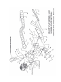
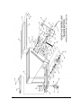
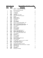
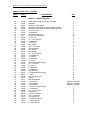
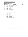
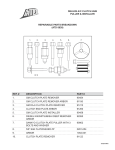
THE GIANT-VAC
1695 TRAIL-VAC
MODEL 1695
OPERATOR’S MANUAL
Congratulations!
You have just purchased one of the finest pieces of outdoor power equipment on the
market today. If properly cared for, your Giant-Vac Model 1695 Trail-Vac will provide
years of dependable service. Please read and follow this instruction manual carefully in
order to get the most out of your new equipment.
First, inspect your machine upon delivery. Each Giant-Vac product leaves our factory in
excellent condition; occasionally, however, some damage may occur during shipment. If
any such damage is found upon initial inspection, immediately notify the transport carrier
who delivered your machine, as they are solely responsible for the damage as well as
any subsequent adjustments.
Your Giant-Vac Model 1695 Trail-Vac comes completely assembled. Simply follow the
instructions contained within this manual to begin enjoying the benefits of your new unit.
CALIFORNIA PROPOSITION 65 WARNING
Gasoline and Diesel engine exhaust and some of its constituents are
known to the State of California to cause cancer, birth defects and other
reproductive harm.
As an owner of off-road gasoline or diesel engine equipment and/or as an
employer, you also may have an obligation under the California
Occupational Safety and Health Act or under Proposition 65 to warn
persons exposed to gas and diesel engine exhaust and/or other
Proposition 65 chemicals in and around your workplace. See California
Health and Safety Code section 25249.5, Title 22 of the California Code of
Regulations at Section 1200 er seq., and Title 8 of the California Code of
Regulations Section 5194.
3/01 REV.
Manual No. 3079072 (3/2001)
1
SAFETY RULES REGARDING OUTDOOR
POWER EQUIPMENT
IMPORTANT!
READ THE FOLLOWING SAFETY RULES
CAREFULLY BEFORE OPERATING UNIT:
•
Regard your Giant-Vac Model 1695 Trail-Vac as a piece of power
equipment and teach this regard to all who will operate this unit. Never
allow children or young teenagers to operate the unit.
•
Always wear appropriate safety equipment when operating this unit.
Proper eye, ear, and breathing protection is a must.
•
Be sure you know how to stop both the unit and the engine at a
MOMENT’S NOTICE. Refer to the operation section of this manual, as
well as the engine manual.
•
Do not operate with any guards or component parts removed from unit.
•
Unless there is very good artificial light, use only during daylight.
•
Fill gasoline driven machines outdoors. Avoid spilling gasoline and DO
NOT fill the engine while it is running or while you are smoking.
•
While in operation, keep all parts of body away from intake and exhaust
sections. Never insert any body part or other foreign object in any
opening while the machine is running.
•
Never operate the unit with the back door open or unlocked.
•
When operating unit, keep people and pets a safe distance away.
Instruct children to keep away from the area of operation at all times.
•
Do not use on steep inclines (over 30 degrees), as unit can roll over.
•
Before making any adjustments or repairs, stop engine and remove
spark plug wire.
FAILURE TO FOLLOW THESE RULES CAN RESULT IN CHRONIC
HEALTH PROBLEMS, SERIOUS INJURY, OR EVEN DEATH.
2
UNIT OPERATION
1. CONNECTING UNIT TO TOWING VEHICLE:
Connecting the Model 1695 Trail-Vac to a towing vehicle is fast and easy – simply align
the hole in the forward section of the Trail-Vac’s A-frame hitch with the rear hitch mount
of the towing vehicle, and secure with a heavy-duty hitch pin (not supplied).
2. STARTING THE ENGINE
NOTE: If you experience problems with your engine that cannot be satisfactorily resolved by
following the instructions contained within the engine manual, contact your local engine dealer, or
call the toll-free service number listed in the repair section of the engine manual. All engine
service, warranty or otherwise, is required to be performed by a manufacturer-authorized service
center. Giant-Vac Mfg., Inc. is neither authorized nor responsible for any type of warranty engine
service, nor is it equipped to perform any such service.
BEFORE STARTING ENGINE:
•
Be sure to read your engine manual carefully and thoroughly before attempting to
start the engine.
•
Be sure that the unit is completely assembled, and all safety guards and
components are in place.
•
Be sure to check engine’s oil and gasoline*. (See engine manual for recommended
oil and gasoline specifications.) Never check the engine while it is running or while
you are smoking. Check only when engine is cold.
*All machines are shipped without oil or gasoline unless otherwise noted.
•
Be sure that red fuel valve on engine is set to open position.
TO START ENGINE :
•
Set throttle control up to “full” position. If engine is cold, set choke by pulling out
choke handle.
•
Turn ignition key and hold until engine starts. (If engine fails to start within a
reasonable amount of time, discontinue and check engine manual for further
instructions.)
•
After engine starts, release ignition key, move throttle control down to approximately
half, and turn off choke as required.
TO SHUT ENGINE DOWN :
•
Allow engine to idle for 2-3 minutes before shutting down.
•
Turn ignition key to ‘off’ position.
•
If engine is not to be started for a prolonged period, turn red fuel valve to closed
position.
3. OPERATING THE UNIT:
ADJUSTING THE NOSE CONE:
Adjustable rubber flaps along the entire perimeter of the large 48” nose cone * make
your Model 1695 Trail-Vac suitable for virtually any surface. To adjust the flaps, simply
loosen the bolts securing the flap bolt plates to the nose cone body, and slide the flap
assembly up or down to suit the particular application. Generally, the harder and
smoother the surface (such as parking lots), the closer to the surface the flaps should be
adjusted; the softer and rougher the surface (such as grassy fields), the higher the flaps
should be set. Experience will be your best guide. As a rule of thumb, however, the
rearmost flap should always make contact with whatever surface the Trail-Vac is
operating on.
* Model 1695 MO E has a rotary mower attachment in place of the nose cone. This
option consists of an intake flange that attaches directly to the power unit, a six-foot
length of 6” diameter hose, two 6” hose clamps, and a special universal chute that
attaches to the discharge portion of a mower deck, in place of the deflector. The chute
is adjustable and will fit most model tractors.
UTILIZING THE OPTIONAL NOSE CONE MOUNT HOSE KIT:
In addition, the nose cone is designed to accept an optional intake hose kit, making the
Trail-Vac an incredibly versatile piece of debris removal equipment. This option allows
for easy access into areas that the Trail-Vac is unable to maneuver into. For further
information regarding this and other optional accesories, please refer to the options
section further along in this manual.
To attach the hose kit, first remove the auxiliary intake cover (Parts List Ref. # 36, Sheet
1) from the upper portion of the nose cone body. Then, using the same mounting
hardware, fasten the intake flange to the auxiliary intake, tightening the mounting bolts
securely. Next, slide one hose clamp onto one end of the intake hose, approximately 12” from the end. Slide this end of the hose onto the intake flange, and tighten the clamp
securely. Slide the other hose clamp onto the loose end of the hose in like manner, then
slide the end of the hose onto the intake nozzle. Tighten clamp securely.
To utilize the intake hose kit, remove the nut, lockwasher, and inner door lever clip from
the left side of the nose cone body (Ref #’s 10, 11, 12; refer to Parts List Sheet 1), and
flip the door lever up to a vertical position. This will close the bottom portion of the nose
cone, deflecting all suction to the auxiliary intake. (Helpful hint: If intending to utilize the
hose kit option for an extended period of time, simply invert the clip, slide it back onto the
stud, and secure it with the lockwasher and nut. This will prevent the clip from being lost
or misplaced.)
DUMPING THE LEAF BOX:
Your Giant-Vac Model 1695 Trail-Vac has a 2 cubic yard* self-dumping leaf box. When
the box is full, simply back the unit up to the desired dumping area **, loosen the two
handle nuts on either side of the back door, swing the two pivot lock bolts out of the way,
lift the spring-loaded back door, and the debris will slide out. If necessary, pull the unit
forward a few feet to ensure complete emptying of the box. Be sure to close and lock
the door before resuming operation.
* Approximate holding capacity
** Before backing up, always make a visual assessment of the area behind the
Trail-Vac, making sure there are no people (especially children) or objects behind
the machine that could be backed into or run over. Failure to do so could result in
serious injury, as well as severe machine and/or property damage.
UNIT OPTIONS:
NOSE CONE MOUNT HOSE KIT (MODEL 1696):
This hose kit contains an intake flange that mounts onto the nose cone’s auxiliary intake
(the hole in the upper portion of the nose cone body, covered by the round cover plate),
a ten-foot length of 6” diameter hose, an intake nozzle (complete with handle grip), and
two 6” hose clamps. This handy accessory allows easy access to hard-to-reach places.
DIRECT MOUNT HOSE KIT (MODEL 1606):
This hose kit consists of a flange that bolts directly onto the power unit in place of the
nose cone, a ten foot length of 10” hose, an intake nozzle, and two 10” hose clamps.
The most popular application is for cleaning out such places as shrubbery beds.
3
MAINTENANCE AND STORAGE
•
Follow implicitly the engine manufacturer’s recommendations for maintenance.
•
Never make any adjustments to the Trail-Vac until the engine is off and the spark
plug wire is disconnected.
•
If carburetor adjustment is necessary, stand to one side and keep feet and hands in
the clear while making adjustments.
•
Keep engine free of accumulations of grass, leaves or excessive grease.
accumulation of these combustible materials may result in a fire.
•
Store gasoline in a safe and approved container in a cool dry place.
•
Keep the Trail-Vac and fuel container in locked storage to prevent children from
playing and/or tampering with them.
•
Do not store gasoline powered equipment or fuel containers in a basement or any
closed area where heating or heat appliances or open pilot lights are present, unless
the fuel is completely drained from the power equipment and the fuel containers.
An
GIANT-VAC WARRANTY
GIANT-VAC, INC., here-in-after called Giant-Vac, warrants each new Giant-Vac to the
original retail purchaser of the new Giant-Vac equipment to be free from manufacturing
defects in normal service for a period of 1 year, unless it is used for rental purposes,
which limits the warranty to 30 days. This warranty does not apply to engines, tires or
other parts that are purchased and warranted by their manufacturer. Items such as
bags, grass catchers, hoses and blades are not warranted, as these are considered
expendable items. This warranty does not include equipment failures due to normal
wear.
Any obligation under this warranty is expressly limited to the replacement or repair, at an
authorized servicing Giant-Vac dealer, or at a point designated by us, of such parts as
appear to us to have been defective. All defective parts have to be returned freight
prepaid before credit will be issued.
We shall not be liable for transportation charges in connection with the replacement or
repair of defective parts.
This warranty does not apply to a Giant-Vac upon which repairs or alterations have been
made by others except with our prior written approval.
We shall not be liable for consequential damages or contingent liabilities for the fitness
of any Giant-Vac for any particular purpose.
We make no other express, implied or statutory warranty, nor is anyone authorized to
make any in our behalf.
GIANT-VAC, INC.
P.O. BOX 195
SOUTH WINDHAM, CT. 06266
PHONE: 860-423-7741 • FAX: 860-423-2654
PARTS LIST NO. 5741
REF #
PART #
GIANT-VAC MODEL 1695 TRAIL-VAC –3/01 REV.
DESCRIPTION
QTY
SHEET 1 – POWER UNIT SECTION
1
2
3
4
5
6
7
8
9
10
11
12
13
14
15
16
17
18
19
20
21
22
23
24
25
26
27
28
29
30
31
32
33
34
35
36
37
38
39
39A
*
40
41
42
43
44
10231
31095
31043
31094
31022
39068
31020
21523
27084
27296
31008
31009
31089
31008
27297
27298
27299
31690
31008
31009
31282
31003
31027
27300
27301
27302
31690
31008
31009
31282
31003
31027
27064
31400
31003
20166
34013
34004
20147
31284
70424
24552
31089
31008
31009
24553
Blower housing & engine base
½ x 1-1/4” hex bolt
½” flatwasher
½” lockwasher
½” hex nut
16HP Kohler OHC engine
Impeller bolt, washer & key group
Impeller
Nose cone body
Inner door lever clip
3/8” lockwasher
3/8” hex nut
3/8” x 1” hex bolt
3/8” lockwasher
Nose cone front/rear flap bolt plate – 48”
Nose cone front/rear rubber flap – 48”
Nose cone front/rear flap clamp bracket – 48”
3/8” x 1-1/2” flat slotted machine screw
3/8” lockwasher
3/8” hex nut
5/16” x 1” hex bolt
5/16” lockwasher
5/16” flatwasher
Nose cone side flap bolt plate – 5”
Nose cone side rubber flap – 5”
Nose cone side flap clamp bracket – 5”
3/8” x 1-1/2” flat slotted machine screw
3/8” lockwasher
3/8” hex nut
5/16” x 1” hex bolt
5/16” lockwasher
5/16” flatwasher
Nose cone auxiliary intake cover
5/16” x 3/4” hex bolt
5/16” lockwasher
6” intake flange – Nose cone mount – optional*
6” hose clamp – optional*
6” x 10’ intake hose – optional*
6” intake nozzle – optional*
Intake nozzle handle grip - optional*
1696 Optional nose cone mount hose kit - complete
Discharge chute
3/8” x 1” hex bolt
3/8” lockwasher
3/8” hex nut
Discharge chute flange
1
6
10
6
6
1
1
1
1
1
1
1
8
8
2
2
2
10
10
10
3
3
3
2
2
2
4
4
4
4
4
4
1
4
4
1
2
1
1
1
1
2
4
4
1
Giant-Vac Trail-Vac Model 1695 Operating Instructions
PARTS LIST NO. 5741 – 3/01 REV.
REF #
PART #
DESCRIPTION
QTY
SHEET 2 – TRAILER SECTION
45
46
47
48
48A
49
50
51
52
53
54
55
56
57
58
59
60
61
62
63
64
65
66
67
68
69
70
71
72
73
74
75
76
77
78
78
78
79
80
81
82
83
84
85
86
87
88
27295
27052
37003
37026
37004
31333
31043
37017
31417
31406
31095
31043
31406
37016
31089
31008
31009
37018
31512
31094
31022
31043
31406
37123
31444
31098
31043
31691
33058
33056
33057
33054
31152
33171
31440
31441
31442
31692
31094
31095
33030
33001A
33116
31571
31306
31441
31442
Trailer frame & leaf receiver box assembly
Back door
Back door upper lift arm
Back door lower lift arm & spring bracket–left side
Back door lower lift arm & spring bracket–right side
½” X 3” hex bolt
½” flatwasher
Door lift arm stand-off
Lift arm pivot bolt spacer
½” lock nut
½” x 1-1/4” hex bolt
½” flatwasher
½” lock nut
Door handle
3/8” x 1” hex bolt
3/8” lockwasher
3/8” hex nut
Door spring
½” x 1-3/4” hex bolt
½” lockwasher
½” hex nut
½” flatwasher
½” lock nut
Back door pivot lock bolts
¼” x 1” hex bolt
¼” lock nut
½” flatwasher
½” handle nut
Hub (w/studs)
1” ID tapered roller bearing
1” seal
18-8.50 x 8 tire & rim
Lug nut
Rear axle spindle
1” axle spacer
½” axle spacer
¼” axle spacer
1-14 axle nut (w/set screw)
½” lockwasher
½” x 1-1/4” hex bolt
Caster horn
4.10-350 x 4 wheel
5/8” x 5” axle bolt
5/8” jam lock nut
1” ID flange bushing
½” caster spacer
¼” caster spacer
1
1
2
1
1
4
4
4
12
4
4
6
4
1
2
2
2
2
4
4
4
8
4
2
2
2
2
2
2
4
4
2
8
2
Subject to variation
Subject to variation
Subject to variation
2
4
4
2
2
2
2
4
4
4
Giant-Vac Trail-Vac Model 1695 Operating Instructions
PARTS LIST NO. 5741 – 3/01 REV.
REF #
PART #
DESCRIPTION
QTY
SHEET 2 – TRAILER SECTION (cont.)
89
90
91
92
93
94
95-96
31305
38002
31512
31406
31163
37124
31305
¼” x 2” snapper pin
Trailer hitch
½” x 1-3/4” hex bolt
½” lock nut
Polypropylene screen
Screen hanger rod
¼” x 2” snapper pin
2
1
2
2
1
2
2
ITEMS NOT SHOWN
70863
31294
31003
31004
39020
31642
31643
31009
31008
31836
31837
Replacement housing liner (w/hardware)
5/16-18 x 2-1/2” hex bolt (engine mount bolt)
5/16” lockwasher
5/16-18 hex nut
Battery
Battery cable – 32SS – positive
Battery cable – 16SS – ground
3/8-16 hex nut – ground cable nut
3/8” lockwasher
Battery terminal cover – red
Battery terminal - black
SPECIFICATIONS SUBJECT TO CHANGE WITHOUT NOTICE
1
4
4
4
1
1
1
1
1
1
1