1
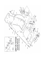
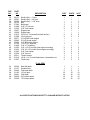
THE GIANT-VAC
GIANT THATCHER
MODELS 55GT – 55GTH – 91GT
ASSEMBLY GUIDE AND OPERATOR’S MANUAL
As you unpack your Giant-Thatcher power unit, you will find the following parts:
1 - Power unit with motor, thatcher reel and wheels mounted
1 - Set of handles in three parts
1 - Height adjustment lever assembly
1 - Package of hardware
Inspect parts for any damage that may have occurred in shipping. If any are found, save the packing
box and IMMEDIATELY notify the transport carrier who delivered your machine, as they are
responsible for the damage, and are the only ones to make any adjustments. Before leaving our
plant, all dimensions are held to close tolerances, and thus, you will have little difficulty in assembling
your Giant-Thatcher if you follow these steps.
CALIFORNIA PROPOSITION 65 WARNING
Gasoline and Diesel engine exhaust and some of its constituents are known to
the State of California to cause cancer, birth defects, and other reproductive
harm.
As an owner of off-road gasoline or diesel engine equipment and/or as an
employer, you also may have an obligation under the California Occupational
Safety and Health Act or under Proposition 65 to warn persons exposed to gas
and diesel engine exhaust and /or other Proposition 65 chemicals in and
around your workplace. See California Health and Safety Code section
25249.5, Title 22 of the California Code of Regulations at section 1200, er seq.,
and Title 8 of the California Code of Regulations section 5194.
12/01 Revision
Manual No. 3079068 (12/2001)
ASSEMBLY INSTRUCTIONS
Note: please refer to parts list for correct parts identification and placement
HANDLE AND THROTTLE ASSEMBLY:
• Insert lower handles (Parts List ref. #7,8) into upper handle (#12) until bolt holes are aligned.
(Note that lower holes in lower handles are set at a 45 degree angle; make sure hole angle in
each lower handle matches corresponding holes in deck.) Fasten left lower-upper junction with
one 5/16 x 1-3/4” hex bolt (#14), securing with lock washer and nut (#15,16). Fasten right side
with one 5/16 x 3-1/4” eye bolt (#18), fitted with one 5/16” nut (#19) threaded about 3/4 way up the
stud, securing with lockwasher and nut (#20,21). Do not tighten these bolts yet. Fasten handle
assembly to engine deck with four 5/16 x 1-3/4” hex bolts, lock washers and nuts (#9-11). Tighten
all bolts except eye bolt.
• Fasten throttle control (#51) to left side of upper handle with two 10-24 x 1 1/4” bolts, lock washers
and nuts (#52). Secure cable to handle assembly with two throttle clips (#53), one about two
inches below the junction of upper and lower handles, the second just below the curve in the
upper handle. Make sure you have left a generous loop between the engine and the bottom clip.
THIS IS IMPORTANT to prevent the throttle binding. After starting your engine, adjust the length
of cable by loosening the screw at the throttle lever for proper engine operation.
HEIGHT ADJUSTMENT LEVER ASSEMBLY/INSTALLATION:
• Slip one 1/2” locking collar (#22) onto threaded end of height adjustment handle crank rod (#17a),
sliding both about 1” past upper end of thread. Slide end of rod through eye bolt, then slip second
collar up against eye bolt. Do not tighten collars yet. Next, fit 1/2-13 wing nut (#23), wings first,
onto end of crank rod, threading up to end of thread. Fit 1/2” jam nut (#17c) onto threaded end of
lower connecting rod (#17d), threading it down about halfway. Thread one end of adjustment
handle main tube (#17b) down to meet jam nut. Tighten jam nut against main tube. Slip angled
end of lower connecting rod into hole in right side plate of height adjustment frame (#24), securing
with bridge pin (#25). Thread end of crank rod about 1 – 1-1/2” into upper end of main tube.
Adjust crank rod placement on eye bolt so that bar of height adjustment frame butts against
bumper bar. Slip both upper and lower sets of collars/washers against eye bolt and tighten collars
with allen wrench. Thread wing nut against main tube. Tighten nuts securing eye bolt to handle
assembly.
Assembly of your Giant-Vac Thatcher is now complete.
SAFETY AND OPERATING INSTRUCTIONS
MOTOR INSTRUCTIONS:
You have received a complete engine manual with your machine. Be sure to especially note the
instructions on OILING. ALL MACHINES ARE SHIPPED WITHOUT OIL OR GASOLINE UNLESS
OTHERWISE NOTED. If you have any difficulties with the engine, check the Yellow Pages of your
phone book for the engine dealer nearest you, rather than us, as the engines are under their own
manufacturer's warranty.
STARTING INSTRUCTIONS:
Before starting the engine, make certain that the deck is raised to clear the thatching blades of the
ground. This is done by turning the crank rod on the height adjustment lever counterclockwise until
the height adjustment frame bar butts against the bumper bar. Sock the wing nut tight against the
main tube. CHECK TO BE CERTAIN THE THATCHER BLADES ARE CLEAR OF THE GROUND.
NOTE: WHEN THE ENGINE IS RUNNING, THE BLADES ARE ROTATING. (This unit is direct
drive.) Never start the engine until you are ready to thatch. Place the throttle control in middle
position, pull out the choke and start the engine. Loosen the height adjustment wing nut, then turn the
height adjustment crank rod clockwise just until the blades begin cutting the soil. Unless
recommended by a turf specialist, you should not thatch too deep. Push the machine in a straight
line. At the end of a path, raise the thatching reel by turning the crank rod counterclockwise as
before. Turn the machine around and follow back along the previously thatched path. We definitely
recommend this back and forth pattern rather than a square pattern as a more uniform thatching job
will result. Make certain your Giant-Thatcher is in a raised position before you stop the unit.
CLEAN-UP:
After thatching, the lawn should be thoroughly cleaned to be certain all of the waste is removed. We
strongly recommend a Giant-Vac for this operation. A Giant-Vac will pick up all of this debris and not
push any of the dead thatch back into the soil.
GENERAL MAINTENANCE:
Your Giant-Thatcher has been carefully engineered to give you excellent service. The following are a
few thoughts to keep your maintenance to a minimum. Make certain your Giant-Thatcher is in a
raised position before starting. If it should be in a lowered position, so that the blades are coming in
contact with the ground, an undue strain is placed on the belt. When installing a new reel, make
certain the two flange plates are together and both are on the inside of the main deck. If used in
heavy grass, you might find a build-up of grass around the bearings. This should be periodically
cleaned off in order that the bearings are not over-loaded. When installing new blades, make certain
that all connections are fast before putting your Giant-Thatcher back in action. A bit of care in
operation will multiply the blade life considerably.
TRAINING:
1. Regard your Giant-Thatcher as a piece of power equipment and teach this regard to all who will
operate this unit.
2. Never allow children or young teenagers to operate the Giant-Thatcher.
3. Be sure you know how to stop the engine at a MOMENT’S NOTICE.
4. Instruct children to keep away from the area of operation at all times.
PREPARATION:
1. Before starting operation, clear the entire work area of all debris that could catch on or be thrown
by the Giant-Thatcher.
2. Unless there is very good artificial light, use only during daylight.
3. Fill gasoline driven machines outdoors. Avoid spilling gasoline and DO NOT fill the engine while it
is running or while you are smoking.
OPERATION:
1. NEVER INSERT ANY BODY PART OR OTHER FOREIGN OBJECT IN ANY OPENING WHILE
THE MACHINE IS RUNNING.
2. Do not operate with any guards or component parts removed from unit.
3. Before making any adjustments or repairs, stop engine and remove spark plug wire.
4. While in operation, keep all parts of body away from engine base or thatcher reel.
5. When operating machine, keep people and pets a safe distance away.
6. Before starting, be certain to check the engine’s OIL AND GASOLINE. (See engine
manufacturer’s Service Manual.) NEVER check the engine while engine is running or while you are
smoking. Check ONLY when engine is cold.
7. Before starting the engine, be certain the unit is completely assembled, and the thatcher blades
are clear of the ground. With your right hand, set the throttle control to the “on” position. When the
engine is cold, you might have to initially choke the engine. (The choke lever is next to the carburetor.)
Next, with your left hand, pull the recoil starter rope slowly until you feel compression, then pull fast
and steady. Do not let the recoil starter rope snap back by itself. This may damage the rope or recoil
starter assembly. After the engine starts, move the throttle lever down to approximately halfway.
MAINTENANCE AND STORAGE:
1. Follow implicitly the engine manufacturer’s recommendations for maintenance and storage.
2. Never adjust the Giant-Thatcher until the engine has been turned off and the spark plug wire has
been disconnected.
3. If carburetor adjustment is necessary, stand to one side and keep feet and hands in the clear while
making adjustments.
4. Keep engine free from accumulations of grass, leaves or excessive grease. An accumulation of
these combustible materials may result in a fire.
5. Store gasoline in a safe and approved container in a cool dry place.
6. Keep the Giant-Thatcher and fuel container in locked storage to prevent children from playing
and/or tampering with them.
7. Gasoline powered equipment or fuel containers should not be stored in a basement or any closed
area where heating or heat appliances or open pilot lights are present, unless the fuel is completely
drained from the power equipment and the fuel containers.
GIANT-VAC WARRANTY
GIANT-VAC, INC., here-in-after called Giant-Vac, warrants each new Giant-Vac to the original retail
purchaser of the new Giant-Vac equipment to be free from manufacturing defects in normal service
for a period of 1 year, unless it is used for rental purposes, which limits the warranty to 30 days. This
warranty does not apply to engines, tires or other parts that are purchased and warranted by their
manufacturer. Items such as bags, grass catchers, hoses and blades are not warranted, as these are
considered expendable items. This warranty does not include equipment failures due to normal wear.
Any obligation under this warranty is expressly limited to the replacement or repair, at an authorized
servicing Giant-Vac dealer, or at a point designated by us, of such parts as appear to us to have been
defective. All defective parts have to be returned freight prepaid before credit will be issued.
We shall not be liable for transportation charges in connection with the replacement or repair of
defective parts.
This warranty does not apply to a Giant-Vac upon which repairs or alterations have been made by
others except with our prior written approval.
We shall not be liable for consequential damages or contingent liabilities for the fitness of any GiantVac for any particular purpose.
We make no other express, implied or statutory warranty, nor is anyone authorized to make any in our
behalf.
GIANT-VAC, INC.
P.O. BOX 195
SOUTH WINDHAM, CT. 06266
PHONE: 860-423-7741 • FAX: 860-423-2654
PARTS LIST NO. 5713 – 12/01 Revision
REF. PART
NO.
DESCRIPTION
NO.
1
1
2
3
4
4a
4b
4c
5
6
7
8
9
10
11
12
13
14
15
16
17
17a
17b
17c
17d
18
19
20
21
22
23
24
25
26
27
28
29
30
31
31a
31b
32
33
34
35
36
37
10025
10026
23032
31089
24518
27306
27307
31100
31087
31003
23019
23020
31002
31003
31004
23018
31590
31002
31003
31004
23258
----- *
----- *
----- *
----- *
31618
31004
31003
31004
31085
31787
33230
31126
31086
31815
31012
33010
31461
31022
31476
31043
36138
36139
31046
31003
31004
36130
55GT/55GTH/91GT THATCHER
Engine deck
Engine deck
Bumper bar
3/8 x 1” hex bolt
Steel rear guard apron
Rear rubber flap
Steep rivet strip for rubber flap
3/16” steel rivet
5/16 x 3/4” hex bolt
5/16” lock washer
Lower handle right
Lower handle left
5/16 x 1-3/4” hex bolt
5/16” lock washer
5/16” hex nut
Upper handle
Foam handle grip
5/16 x 1-3/4” hex bolt
5/16” lock washer
5/16” hex nut
Height adjustment handle assembly (4 parts*)
Crank rod
Main tube
1/2” jam nut
Lower connecting rod
5/16 x 3-1/4” eye bolt
5/16” hex nut
5/16” lock washer
5/16” hex nut
1/2” locking collar
1/2-13 wing nut
Height adjustment frame
Bridge pin
1/2 x 1-3/4” hex bolt
1/2” spacer
1/2” hex jam nut
8 x 1.75 wheel
1/2 x 2-1/2” hex bolt
1/2” hex nut
1/2” lock nut
1/2” flat washer (right rear wheel only–not shown)
Flange for bearing
Bearing
5/16 x 3/4” carriage bolt
5/16” lock washer
5/16” hex nut
Large pulley
55GT
55GTH
91GT
1
-1
2
1
1
1
3
2
2
1
1
4
4
4
1
1
1
1
1
1
----1
1
1
1
2
1
1
1
2
2
2
4
4
4
3
2
4
2
6
6
6
1
1
-1
2
1
1
1
3
2
2
1
1
4
4
4
1
1
1
1
1
1
----1
1
1
1
2
1
1
1
2
2
2
4
4
4
3
2
4
2
6
6
6
1
-1
1
2
1
1
1
3
2
2
1
1
4
4
4
1
1
1
1
1
1
----1
1
1
1
2
1
1
1
2
2
2
4
4
4
3
2
4
2
6
6
6
1
REF.
NO.
PART
NO.
38
38
38
39
40
41
42
43
43
44
45
46
46
46
47
47
48
48
49
50
51
52
53
36131
36287
36288
36132
37005
31088
31003
10027
10028
31816
31009
39077
39095
39094
31795
31868
31002
31623
31003
31004
35011
31010
31007
DESCRIPTION
Small pulley – 1” bore
Small pulley – 3/4” bore
Small pulley – 1-1/8” bore
Belt
Belt guard
5/16 x 3” hex bolt
5/16” lock washer
Engine base
Engine base
3/8-16 x 2” full thread bolt (belt tension)
3/8-16 hex nut
5.5 HP B&S Intek engine
5.5 HP Honda engine
9 HP B&S Intek engine
1/4 x 2-1/8” shaft key
3/16” x 2” shaft key
5/16 x 1-3/4” hex bolt (rear engine mounting)
5/16 X 2-1/2” hex bolt (front engine mounting)
5/16” lock washer
5/16” hex nut
Throttle control
10-24 x 1-1/4” round head screw, lockwasher, nut
Throttle clip
55GT
55GTH
91GT
1
--1
1
2
2
1
-2
2
1
--1
-2
2
4
4
1
2
2
-1
-1
1
2
2
1
-2
2
-1
--1
2
2
4
4
1
2
2
--1
1
1
2
2
-1
2
2
--1
1
-2
2
4
4
1
2
2
1
1
6
12
36
12
30
1
1
6
12
36
12
30
1
1
6
12
36
12
30
FLAIL REEL
A1
A2
A3
A4
A5
A6
A7
36036
31107
36040
31106
36041
36038
36039
Main flail shaft
Woodruff key
Flail blade shaft
1/8” roll pins
Flail blade
3/8” rubber spacer
7/8” rubber spacer
ALL SPECIFICATIONS SUBJECT TO CHANGE WITHOUT NOTICE