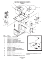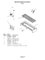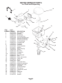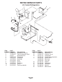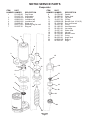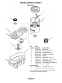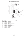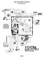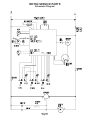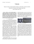
1
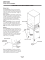
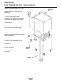
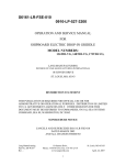
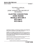
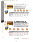
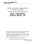
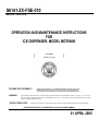
S6161-ZX-FSE-010
0910-LP-103-7479
OPERATION AND MAINTENANCE INSTRUCTIONS
FOR
ICE DISPENSER, MODEL MDT6N90
(
DISTRIBUTION STATEMENT C:
WARNING:
SCOTSMAN
N00024-97-C-2202
)
DISTRIBUTION AUTHORIZED TO U.S. GOVERNMENT AGENCIES AND THEIR CONTRACTORS;
ADMINISTRATIVE/OPERATIONAL USE; (DATE OF PUBLICATION). OTHER REQUESTS FOR
THIS DOCUMENT SHALL BE REFERRED TO THE NAVAL SEA SYSTEMS COMMAND (PMS317).
THIS DOCUMENT CONTAINS TECHNICAL DATA WHOSE EXPORT IS RESTRICTED BY THE ARMS EXPORT CONTROL ACT (TITLE 22, U.S.C. SEC.2751 ET
SEQ.)OR THE EXPORT ADMINISTRATION ACT OF 1979, AS AMENDED, TITLE 50 U.S.C., APP 2401, ET SEQ. VIOLATIONS OF THESE EXPORT LAWS ARE
SUBJECT TO SEVERE CRIMINAL PENALTIES.
DESTRUCTION NOTICE:
DESTROY BY ANY METHOD THAT WILL PREVENT DISCLOSURE OF CONTENTS OR RECONSTRUCTION OF THE DOCUMENT.
PUBLISHED BY DIRECTION OF COMMANDER, NAVAL SEA SYSTEMS COMMAND
01 APRIL 2005
Scotsman Ice Systems
775 Corporate Woods Parkway
Vernon Hills, IL 60061
PH: (800) SCOTSMAN or 800-726-8762
FAX: (847)913-9844
MDT6N90
INTRODUCTION
To the owner or user: The service manual you are
reading is intended to provide you, and the
maintenance or service technician with the
information needed to install, start up, clean,
maintain, and service this ice maker-dispenser.
The MDT6 is a combination nugget ice maker and
countertop dispenser. A water station is standard.
The ice making section is equipped with the
following features: electronic controls for bin level
and low water; thermostatic expansion valve; front
service for most components; and R-404A
refrigerant. The ice dispensing section is a
seamless plastic storage bin, with a stainless steel
ice agitator at the bottom to sweep the ice into the
dispensing chute.
Table of Contents
FOR THE INSTALLER: Specifications · · · · · · · · · · · ·
FOR THE INSTALLER · · · · · · · · · · · · · · · · · · · ·
FOR THE PLUMBER · · · · · · · · · · · · · · · · · · · · ·
FOR THE ELECTRICIAN · · · · · · · · · · · · · · · · · · ·
FOR THE INSTALLER: Final Check List · · · · · · · · · · ·
INITIAL START UP · · · · · · · · · · · · · · · · · · · · · ·
COMPONENT DESCRIPTION · · · · · · · · · · · · · · · ·
COMPONENT DESCRIPTION · · · · · · · · · · · · · · · ·
CONTROL BOX · · · · · · · · · · · · · · · · · · · · · · ·
ELECTRICAL SEQUENCE · · · · · · · · · · · · · · · · · ·
OPERATION: Water · · · · · · · · · · · · · · · · · · · · ·
OPERATION: Refrigeration · · · · · · · · · · · · · · · · · ·
OPERATION: Ice Vending · · · · · · · · · · · · · · · · · ·
DISPENSE AREA SANITATION · · · · · · · · · · · · · · ·
CLEANING and SANITIZING · · · · · · · · · · · · · · · · ·
SENSOR MAINTENANCE · · · · · · · · · · · · · · · · · ·
BEARING MAINTENANCE · · · · · · · · · · · · · · · · · ·
AUGER MAINTENANCE · · · · · · · · · · · · · · · · · · ·
SERVICE DIAGNOSIS · · · · · · · · · · · · · · · · · · · ·
CONTROL SYSTEM DIAGNOSTICS · · · · · · · · · · · ·
REMOVAL AND REPLACEMENT · · · · · · · · · · · · · ·
REMOVAL AND REPLACEMENT: Bearing And Breaker · ·
REMOVAL AND REPLACEMENT · · · · · · · · · · · · · ·
REMOVAL AND REPLACEMENT: Water Seal · · · · · · · ·
REMOVAL AND REPLACEMENT · · · · · · · · · · · · · ·
TO REMOVE AND REPAIR THE GEARMOTOR ASSEMBLY
REFRIGERATION SERVICE · · · · · · · · · · · · · · · · ·
·
·
·
·
·
·
·
·
·
·
·
·
·
·
·
·
·
·
·
·
·
·
·
·
·
·
·
·
·
·
·
·
·
·
·
·
·
·
·
·
·
·
·
·
·
·
·
·
·
·
·
·
·
·
·
·
·
·
·
·
·
·
·
·
·
·
·
·
·
·
·
·
·
·
·
·
·
·
·
·
·
·
·
·
·
·
·
·
·
·
·
·
·
·
·
·
·
·
·
·
·
·
·
·
·
·
·
·
·
·
·
·
·
·
·
·
·
·
·
·
·
·
·
·
·
·
·
·
·
·
·
·
·
·
·
·
·
·
·
·
·
·
·
·
·
·
·
·
·
·
·
·
·
·
·
·
·
·
·
·
·
·
·
·
·
·
·
·
·
·
·
·
·
·
·
·
·
·
·
·
·
·
·
·
·
·
·
·
·
·
·
·
·
·
·
·
·
·
·
·
·
·
·
·
·
·
·
·
·
·
·
·
·
·
·
·
·
·
·
·
·
·
·
·
·
·
·
·
·
·
·
·
·
·
·
·
·
·
·
·
·
·
·
·
·
·
·
·
·
·
·
·
·
·
·
·
·
·
·
·
·
·
·
·
·
·
·
·
·
·
·
·
·
·
·
·
·
·
·
·
·
·
·
·
·
·
·
·
·
·
·
·
·
·
·
·
·
·
·
·
·
·
·
·
·
·
·
·
·
·
·
·
·
·
·
·
·
·
·
·
·
·
·
·
·
·
·
·
·
·
·
·
·
·
·
·
·
·
·
·
·
·
·
·
·
·
·
·
·
·
·
·
·
·
·
·
·
·
·
·
·
·
·
·
·
·
·
·
·
·
·
·
·
·
·
·
·
·
·
·
·
·
·
·
·
·
·
·
·
·
·
·
·
·
·
·
·
·
·
·
·
·
·
·
·
·
·
·
·
·
·
·
·
·
·
·
·
·
·
·
·
·
·
·
·
·
·
·
·
·
·
·
·
·
·
·
·
·
·
·
·
·
·
·
·
·
·
·
·
·
·
·
·
·
·
·
·
·
·
·
·
·
·
·
·
·
·
·
·
·
·
·
·
·
·
·
·
·
·
·
·
·
·
·
·
·
Page 2
Page 3
Page 4
Page 5
Page 6
Page 7
Page 8
Page 9
Page 10
Page 11
Page 12
Page 13
Page 14
Page 15
Page 16
Page 17
Page 18
Page 19
Page 20
Page 21
Page 22
Page 23
Page 24
Page 25
Page 26
Page 27
Page 28
Note this symbol when it appears.
This manual was printed on recycled paper.
Keep it for future reference.
May 2001
Page 1
It marks a possible hazard.
MDT6N90
FOR THE INSTALLER: Specifications
This ice maker-dispenser is designed to be
mounted on a machine stand, or a countertop.
Before beginning the installation, check that all the
materials and kits required are available at the
installation location.
Scotsman Ice Systems are designed and
manufactured with the highest regard for safety
and performance. They meet or exceed the
standards of U.L., N.S.F., and C.U. L.
Scotsman assumes no liability or responsibility of
any kind for products manufactured by Scotsman
that have been altered in any way, including the
use of any parts and/or other components not
specifically approved by Scotsman.
Scotsman reserves the right to make design
changes and/or improvements at any time.
Specifications and designs are subject to change
without notice.
BACK VIEW
Water Limitations:
An ice machine is a food
manufacturing plant; it takes in
a raw material, water, and
turns it into a food product,
ice. The purity of the water is
very important in obtaining
pure ice and in maximizing
product life.
General recommendations
Electrical Junction are:
Box
1. Filter the water used to
produce ice.
3/8" Flare
Water Inlet
2. Check with a water
treatment specialist for a water
test, and any
6.63"
recommendations regarding
12.5" filters and treatment.
3/8" FPT
Cond. Water
Inlet
(W/C)
1/2" FPT
Cond. Drain
(W/C)
3/4 FPT
Drain
4.63"
3.84"
.75"
3/4" FPT
Drain
Model Number Model
Series
5.59"
17.59"
Dimensions
(w/o stand)
H" x W" x D"
MDT6N90AS-1 A or B 45.74 x 35.18 x 29.26
MDT6N90WS-1 A
same
MDT6N90WS-1 B
same
2.63"
7.93"
Condenser Refrigerant
Basic
Minimum
Type
Charge
Electrical
Circuit
(R-404A)
Ampacity*
Air
32
115/60/1
18.1
Water
22
same
16.5
Water
19
same
16.5
*Minimum circuit ampacity is used to determine wire size and type per National Electric Code.
Options: Machine stand DMS31.
June 2002
Page 2
Max.
Fuse
Size
25
20
20
MDT6N90
FOR THE INSTALLER
Location
This ice system is designed to be installed indoors,
in a controlled environment.
Minimum
Maximum
1000F.
Air Temp
500F.
1000F.
Water Temp
400F.
Water Pressure 20 psi
80 psi
Voltage
104
126
Operating the machine outside of the above
limitations, or outdoors, is potentially damaging to
the machine; also it is misuse of the machine
which may void the warranty.
Service Limitations
Do not install in a location where the top of the
machine is within 6" of a fixed ceiling. Air cooled
models require a minimum of 6 inches to the left
and right of the machine for air circulation. It is
important that the machine be installed in a
location where it has enough space above and
behind it for service.
After uncrating and inspection, the unit is ready for
installation.
Machine Stand Installation
Tip the stand on its back and install the legs, return
the stand to the upright position. Adjust leg levelers
so that the stand does not “rock”.
Counter Top or Machine Stand Installation
The base of the icemaker-dispenser must be
sealed to the object it rests upon. Food grade
silastic sealant such as Scotsman part number
19-0529-01 is recommended.
Place a bead of the sealant on the machine stand
or counter top to match the outside edge of the
cabinet base and sink.
The icemaker-dispenser is heavy: use of a
mechanical hoist is recommended to lift it to the
height required to install it.
The DMS machine stand has holes in the top that
match up with threaded holes in the base of the
machine. Secure the machine stand to the base
with 4 5/16" bolts.
In both counter top and machine stand
installations, wipe off and neatly smooth any
excess sealant. Level the machine stand and
cabinet.
Unpack and install the sink brackets. Fit the sink
assembly onto the two sink brackets, and press
onto the bead of sealant. Wipe off and neatly
smooth any excess sealant from under the sink
edge. Connect the sink drain to the dispenser drain
system.
SEAL
ICEMAKERDISPENSER TO
THE COUNTER
TOP OR
MACHINE STAND
May 2001
Page 3
Airflow
MDT6N90
FOR THE PLUMBER
CONFORM TO ALL APPLICABLE CODES
Water Inlet
Air Cooled Models: Connect a clean, potable
and cold water supply to the 3 8” male flare at the
back of the cabinet. Install a hand valve near the
machine to control the water supply. Use 3 8” O.D.
copper tubing.
Water Treatment: In most areas, a water filter of
some type will be useful. In areas where the water
is highly concentrated with minerals the water
should be tested by a water treatment specialist,
and the recommendations of the specialist
regarding filtration and/or treatment should be
followed.
Water Cooled Models: Connect a separate 3 8”
INLET WATER
O.D. copper line, with a separate hand valve to
control it, to the 3 8” FPT condenser inlet at the
back of the cabinet. The water pressure to all lines
must always be above 20 psig, and below 120
psig.
Drains
Air Cooled Models: Connect a drain tube to the
one ¾” FPT drain fitting (plastic) at the back of the
cabinet, the drain line is of the gravity type, and ¼
inch per foot fall is an acceptable pitch for the
drain tubing. There should be a vent at the
highest point of the drain line, and the ideal drain
receptacle would be a trapped and vented floor
drain. Use only ¾” rigid tubing.
WATER COOLED
VENTED
DRAIN
OPTIONAL
WATER
FILTER
SHUT OFF VALVE
CONDENSER
WATER INLET
FLOOR DRAIN
CONDENSER
DRAIN
Water Cooled Models: In addition to the above
mentioned drain, a separate condenser drain line
must be installed. Connect it to the ½ " condenser
drain connection at the back of the cabinet.
May 2001
Page 4
MDT6N90
FOR THE ELECTRICIAN
CONFORM TO ALL APPLICABLE CODES
Connect the electrical power supply for the unit to
the wires in the junction box at the rear of the
machine.
Check the nameplate (located on the back panel)
for the voltage requirements, and for the minimum
circuit ampacity. The machine requires a solid
chassis to earth ground wire.
The ice maker should be connected to its own
electrical circuit so it would be individually fused.
Voltage variation must remain within design
limitations, even under starting conditions.
All external wiring must conform to national,
state, and local electrical codes. The use of a
licensed electrician is required to
perform the electrical installation.
POWER SUPPLY
ELECTRICAL
CONNECTION
May 2001
Page 5
MDT6N90
FOR THE INSTALLER: Final Check List
1. Is the icemaker-dispenser installed
indoors, in a location where the air and
water temperatures are controlled, and
where they do not go beyond design
limitations?
ELECTRICAL
2. is there an electrical service
disconnect within sight of the installed
machine? Is the machine on a separate
circuit? Has the voltage been checked
and compared to nameplate
requirements?
3. Have all of the plumbing connections
been made and checked for leaks?
4. Has the machine been leveled?
5. Is there a minimum of 6 inches of
clearance at the left and right sides of an
air cooled machine?
6. Is there a minimum of 6 inches of
clearance at the top and back of the
machine for service and utility
connections?
7. Is there a water shut off valve installed
near the machine?
8. Have all of the shipping blocks been
removed?
WATER
INLET
DRAINS
May 2001
Page 6
LEVELED
MDT6N90
INITIAL START UP
Pre Start Inspection
1. Remove the two front panels.
2. Check that all shipping blocks have been
removed.
3. Remove any and all packing tape (check inside
the storage bin).
4. Inspect the interior of the machine for loose
screws or wires. Check that no refrigerant lines are
rubbing each other. Check that the fan blade on air
cooled models turns freely.
5. Check that the machine is installed correctly
according to the final check list.
Start Up
1. Go through the pre start inspection.
2. Open the water hand valve, observe that water
enters the water reservoir, fills the tube from the
reservoir to the evaporator and then shuts off.
Check for leaks.
3. Switch the mode switch to ON. The auger drive
motor and compressor start, beginning the ice
making process.
4. On air cooled models, warm air will begin to flow
from the condenser. Water cooled models will
begin to discharge warm water down the drain.
5. The unit should soon be making ice. If desired,
the low side pressure may be checked: it should be
38 PSIG + or - 4 PSIG.
The air cooled discharge pressure will depend
upon air and water temperatures, but should be
between 200 PSIG and 300 PSIG.
Water cooled discharge pressure should be about
245 PSIG. If needed, adjust the water regulating
valve.
The above numbers are for new, clean machines.
Field values may be somewhat higher or lower.
7. Check ice dispensing by pushing in on the glass
filler lever. Ice dispenses are portion controlled; by
turning a knob, the length of time the unit
dispenses when the glass filler lever is pushed
(and the amount of ice dispensed) is adjusted.
8. Switch off the icemaker-dispenser, remove the
top panel and the top of the ice storage bin.
Sanitize the interior of the ice storage bin with a
locally approved sanitizer. A possible sanitizer is a
mixture of 1 ounce of household bleach to 2
gallons of water. Wash the interior of the bin with
the sanitizing solution. Replace all covers and
panels. Switch the icemaker-dispenser back on.
9. Give the owner/user the service manual, instruct
him/her in the operation and maintenance
requirements of the unit. Make sure they know who
to call for service.
10. Fill out the Customer Evaluation and warranty
Registration form, and mail it in to Scotsman.
6. There are no adjustments to make, so replace
the panels.
May 2001
Page 7
MDT6N90
COMPONENT DESCRIPTION
RESERVOIR
WATER
LEVEL
SENSOR
ICE LEVEL SENSOR
ICE STORAGE BIN
CONTROL BOX
EVAPORATOR
DRAIN
TUBE
CONDENSER
HI
PRESSURE Ice Level Sensor: An electronic “eye”, it senses
the presence of ice in the bottom of the ice
CUT OUT
discharge chute. Operates to turn the ice machine
on and off automatically as the level of ice in the
bin changes.
Control Box: Contains the electrical controls that
operate the machine.
High Pressure Cut Out Switch: An automatic
reset switch sensing the high side refrigeration
pressure. It is set to shut the machine off if the
discharge pressure should ever exceed 450 psig.
Evaporator: A vertical stainless steel tube,
refrigerated, and water filled. In it there is a
stainless steel auger.
Reservoir: Float operated, it maintains the water
level in the evaporator at a constant level, it also
contains the water level sensor.
Water Level Sensor: Senses if there is water in
the reservoir to make ice out of. Will shut the
machine off it there is none.
Drain Tube: When uncapped and lowered, drains
the evaporator.
Condenser: Air or water cooled, where the heat
removed in ice making is discharged.
Ice Storage Bin Assembly: A plastic lined,
insulated cylinder that receives, stores and
dispenses the ice. Fresh ice enters at the top, and
when the bin is full enough the ice will be between
the ice level sensors, and the icemaking will stop.
Ice is dispensed through a chute at the bottom
front when the agitator assembly sweeps the ice
through the chute.
May 2001
Page 8
MDT6N90
COMPONENT DESCRIPTION
Evaporator: A refrigerated vertical tube filled with
water and containing a water seal and auger.
Auger: A solid stainless steel double spiral auger,
it pushes the ice crystals up to the top of the
evaporator.
Water Seal: A two part “face” seal, the top half
rotating with the auger, the bottom half stationary,
the sealing action being where the two seal “faces”
meet.
Ice Sweep: A plastic cap with “fingers”. It revolves
with the auger to “sweep” the ice into the ice chute.
Breaker: Where the ice is compressed and much
of the extra water is squeezed out of it before it is
discharged into the bin.
Motor: A split phase motor that drives the gear
reducer.
Thrust Bearing: As the ice is pushed up the
evaporator, the auger is thrust down, and pressure
from the auger thrust is taken up by this bearing.
ICE SWEEP
BEARING
BREAKER
ICE CHUTE
EVAPORATOR
AUGER
WATER SEAL
WATER INLET
GEAR MOTOR
May 2001
Page 9
MDT6N90
CONTROL BOX
Circuit Board:
The circuit board receives input signals from
several sensors and translates them to control the
electrical power supply to the various loads.
The sensors include:
· Touch Free ice or water.
· Ice level in the bin.
· Water level in the reservoir.
The loads include:
· Compressor contactor
· Fan motor
· Bin drive motor
· Auger drive motor
· Water solenoid.
In addition, a “Clean” switch is
available to temporarily disable the
Touch-Free sensors for cleaning of the
splash panel.
On/Off Switch: Manual control for the
machine.
Contactor: A definite purpose
contactor connecting the compressor
to the power supply.
Potential Relay: The compressor
start relay.
Touch Free Control Board
May 2001
Page 10
MDT6N90
ELECTRICAL SEQUENCE
Refer the wiring diagram as needed.
The “Power” light on the board glows whenever
there is power to the machine (and the master
switch is ON).
If the machine is switched off at the master switch,
but is otherwise ready to go, switching the master
switch to ON does the following:
· The bin empty and power lights on the circuit
After a 6 minute delay, If the ice level sensor is
clear (bin empty) for more than 15 seconds, the
machine will start up again.
Another purpose of the circuit board is to turn the
machine off if there is not enough water in the
machine.
· When the water level
in the reservoir falls
below the tip of the water level sensor, the
machine will “shut down”
board glow.
· After a 6 minute delay, if the water refills the
· There is a 15 second delay
· If there is enough water in the reservoir, the
circuit board will allow the machine to start up.
Start up consists of:
reservoir, the machine will start up again.
Separate from the circuit board:
· If the high pressure control (cut out switch)
opens, the compressor will stop immediately
(through the contactor). It will automatically
reset when the discharge pressure drops below
350 PSIG.
· The compressor contactor coil receives power
from the circuit board.
· The contactor is energized, connecting power to
the compressor, and the compressor starts.
· The auger motor receives power from the circuit
board and starts.
· As ice goes past the ice level sensors, the bin
empty light will stay on and the machine will
continue to run, unless the ice stays between
the sensors for more than 15 seconds (bin full).
At that point, the bin empty light goes out, and
the machine shuts down.
Other reasons for shut down:
· The master switch is the manual control for the
complete machine, but it is not a service
disconnect.
Ice Vending
· When a user places a container in front of the
· Low water level (as sensed by the thermistor in
the reservoir).
Shut Down consists of:
· The compressor contactor opens
· The compressor stops
· The auger motor is run by the circuit board for 2
more minutes, clearing out ice in the evaporator,
and then
· The auger motor no longer receives power from
the circuit board, and the auger motor stops.
May 2001
Page 11
Touch Free ice sensor and below the ice
delivery chute, the circuit board connects power
to the bin drive motor and ice is dispensed for
as long as the container is present. If the user
does not remove the container, ice will be
dispensed for 60 seconds and then stop.
MDT6N90
OPERATION: Water
Water enters the machine through the 3/8" male
flare at the rear of the cabinet, goes to the water
reservoir which it enters through the float valve.
The water then goes out the bottom of the
reservoir tank to the bottom of the evaporator.
Reservoir overflow, evaporator condensation and
water in the sink are all routed to the drain. Water
cooled models have a separate water circuit for the
cooling water: it enters the fitting at the rear, goes
to the water regulating valve, then to the water
cooled condenser and down the drain.
The water dispensing station adds an additional
water circuit. When the water station sensor
detects a container in front of it, the control board
closes a circuit to an electric water valve and water
is dispensed.
Note: The correct water level is determined when
the machine is operating. Check the water level
and compare it to the line molded into the side of
the reservoir. The water level should be between
" above and " below the line.
If needed, adjust the water level by bending the
float arm.
WATER LEVEL
RESERVOIR
RESERVOIR
OVERFLOW DRAIN
WATER
INLET
BIN DRAIN
WATER VALVE
SINK DRAIN
WATER SCHEMATIC
May 2001
Page 12
MDT6N90
OPERATION: Refrigeration
Beginning at the compressor, the refrigerant is
compressed into a high temperature gas. The
discharge line directs this gas to the condenser. At
the condenser (air or water cooled) the gas is
cooled by either air or water and it then condenses
into a liquid. This high pressure liquid then goes
through the liquid line to the expansion valve.
The thermostatic expansion valve meters liquid
refrigerant into the evaporator, the volume of liquid
refrigerant depending upon the temperature of the
evaporator; warmer evaporators get more
refrigerant and colder evaporators get less.
At the evaporator, the refrigerant enters an area of
relatively low pressure, where it can easily “boil off”
or evaporate. As it evaporates, it absorbs heat
from the evaporator and whatever is in contact with
it (such as the water inside it). After the evaporator,
the refrigerant, now a low pressure vapor, goes
through the suction line back to compressor, where
the cycle is repeated.
REFRIGERATION SCHEMATIC
(AIR COOLED SHOWN)
SUCTION LINE
THERMOSTATIC
EXPANSION VALVE
LIQUID LINE
DISCHARGE
LINE
CONDENSER
EVAPORATOR
FAN MOTOR
COMPRESSOR
May 2001
Page 13
MDT6N90
OPERATION: Ice Vending
When the ice dispensing sensor detects a
container in front of it, the control board connects
an electrical circuit to the ice chute door solenoid
causing the ice chute door to open. At the same
time power is connected to the agitator drive
motor.
Dispensing takes place when the agitator sweeps
the ice through the ice dispensing chute: ice will
continue to discharge out this chute as long as the
agitator is turning. It stops when the agitator stops.
ICE DISCHARGE CHUTE
DOOR
SOLENOID
ICE CHUTE
DOOR
STORAGE BIN
ICE CHUTE
AGITATOR
AGITATOR
DRIVE MOTOR
TOUCH FREE
SENSOR
SINK
May 2001
Page 14
DISPENSE AREA SANITATION
The dispense area; spouts, sink, grill and splash
panel will need periodic cleaning and maintenance.
1. The ice chute may be pulled down to remove it
from the ice dispenser. Wash and sanitize it.
2. The sink grill may be removed for washing and
sanitizing.
3. The sink should be flushed with hot water and
wiped clean with sanitizer.
4. The splash panel requires special attention to
clean it.
· Push and release the Splash Panel Cleaning
switch located to the left of the water spout. This
disables the Touch Free sensors so the splash
panel may be cleaned without vending ice
and/or water.
· Wash the splash panel and wipe with with
sanitizer.
Re-push the clean switch or allow 2 minutes to
pass for the Touch Free system to reset.
May 2001
Page 15
MDT6N90
MDT6N90
CLEANING and SANITIZING
It is the USER’S RESPONSIBILITY to see that the unit is properly maintained. It is always preferable, and
less costly in the long run, to avoid possible down time by keeping it clean; adjusting it as needed; and by
replacing worn parts before they can cause failure. The following is a list of recommended maintenance
that will help keep the machine running with a minimum of problems.
Cleaning should be scheduled at a minimum of twice per year.
Sanitizing of the ice storage bin should be scheduled for a minimum of 4 times a year.
Electrical power will be ON when doing in place
cleaning.
ICEMAKING SYSTEM: In place cleaning
1. Check and clean any water treatment devices, if
any are installed.
2. Remove screws and remove the upper front
panel.
3. Move the ON-OFF switch to OFF.
4. Remove the cover to the ice storage bin, and
remove the ice.
5. Remove the cover to the water reservoir and
block the float up.
6. Drain the water reservoir and freezer assembly
using the drain tube attached to the freezer water
inlet. Return the drain tube to its normal upright
position and replace the end cap.
7. Prepare the cleaning solution: Mix eight ounces
of Scotsman Ice Machine Cleaner with three quarts
of hot water. The water should be between 90-115
degrees F.
Scotsman Ice Machine
Cleaner contains acids.
These compounds may
cause burns. If swallowed,
DO NOT induce vomiting.
Give large amounts of
water or milk. Call
Physician immediately. In
case of external contact,
flush with water. Keep out
of the reach of children.
10. After all of the cleaning solution has been
added to the reservoir, and the reservoir is nearly
empty, switch the master switch to OFF.
11. After draining the reservoir, as in step 6, wash
and rinse the water reservoir.
To Sanitize:
Repeat steps 8-11, except substitute sanitizer
solution for the cleaning solution.
A possible sanitizer solution may be made by
mixing 1 ounce of household bleach and 2 gallons
of warm (95oF. - 115oF.) potable water.
12. Remove the block from the float in the water
reservoir.
13. Switch the master switch to ON
14. Continue ice making for at least 15 minutes, to
flush out any cleaning solution. Check ice for acid
taste - continue icemaking until ice tastes sweet.
DO NOT USE any ice produced from the
cleaning solution.
Be sure no ice remains in the bin.
15. Remove all ice from the storage bin.
16. Add warm water to the ice storage bin and
thoroughly wash and rinse all surfaces within the
bin.
17. Sanitize the bin interior, cover, door and
agitator with an approved sanitizer using the
directions for that sanitizer.
18. Replace the ice storage bin cover, and the front
panel.
8. Slowly pour the cleaning solution into the water
reservoir until it is full. Wait 15 minutes, then
switch the master switch to ON.
9. As the ice maker begins to use water from the
reservoir, continue to add more cleaning solution to
maintain a full reservoir.
May 2001
Page 16
MDT6N90
SENSOR MAINTENANCE
1. The ice machine senses water level by a probe
located in the water reservoir. At least twice a year,
the probe should be removed from the reservoir,
and the tip wiped clean of mineral build-up.
2. The bin control uses devices that sense light,
therefore they must be kept clean enough so that
they can “see”. At least twice a year, remove the
bin control sensors from the ice chute, and wipe
them clean.
SLIDE SENSORS
UP TO REMOVE
Clean the Probe's Tip with ice
machine cleaner and a clean,
soft cloth.
May 2001
Page 17
MDT6N90
BEARING MAINTENANCE
The bearing in the breaker should also be checked
at least two times per year.
A. Check the bearing by:
· unscrewing the breaker cover.
Auger Stud
· removing the ice chute cover
Ice Sweep
Cap Screw
· unscrewing the auger stud
· unscrewing the ice sweep
· removing the water shed
Breaker
Cover
Off
Inspect the bearing. There should be plenty of
grease in sight. If grease is needed the bearing
and breaker should be removed to check the
action of the bearing. It should rotate smoothly.
To remove the breaker remove the lower ice chute
then take out all four allen head cap screws and
pull the breaker off the auger and evaporator.
If the bearing only needs grease, inject grease into
the bearing using Scotsman grease needle pn
02-3559-01 and Scotsman bearing grease
cartridge, pn A36808-001. Be sure to inject grease
evenly and thoroughly.
See Removal and Replacement section to replace
bearing or seals.
Bearing
Reverse to reassemble.
May 2001
Page 18
Needle, pn
02-3559-01
MDT6N90
AUGER MAINTENANCE
In some areas, the water supply to the ice maker
will contain a high concentration of minerals, and
that will result in an evaporator and auger
becoming coated with these minerals, requiring a
more frequent removal than twice per year. If in
doubt about the condition of the evaporator and
auger, the auger can be removed so the parts can
be inspected.
Note: Water filters can filter out suspended solids,
but not dissolved solids. “Soft” water may not be
the complete answer. Check with a water
treatment specialist regarding water treatment.
For more information on removal of these
parts, see REMOVAL AND REPLACEMENT.
Moving Parts Hazard.
Disconnect electrical
power to the icemaker dispenser before
beginning.
Disconnect electrical power, and shut off the
water supply.
Use care when removing the auger, it has
sharp edges.
1. To remove the auger, remove the front and top
panels.
2. Drain evaporator using drain hose.
3. Remove bail clamp from over ice chute cover
and remove cover.
4. Unscrew and remove ice sweep.
5. Remove ice chute from evaporator.
6. Remove 4 allen screws holding breaker to
evaporator.
7. Pull up to remove auger.
After the auger has been removed, allow the auger
to dry: if the auger is not bright and shiny, it must
be cleaned.
Clean the auger and evaporator as required. DO
NOT HONE THE EVAPORATOR.
8. Replace the water seal.
9. Reverse to reassemble.
May 2001
Page 19
BREAKER AND
AUGER ASSEMBLY
MDT6N90
SERVICE DIAGNOSIS
Symptom
No ice is made, nothing operates
No ice, auger motor is turning
Unit makes ice, but very slowly.
Possible Cause
Unit off due to no power
Unit off due to master switch in
OFF position.
Unit off due to low water level.
Probable Correction
Restore Power
Switch master switch to ON.
Check water supply, filter, float
valve. Correct water supply.
Check/clean ice level sensors.
Unit off due to ice level sensors
(photo-electric eyes) blocked.
Unit off due to scale on water level Clean water level sensor.
sensor.
Unit off due to high pressure
Check for water interruption (water
control open.
cooled) or fan motor failure (air
cooled).
Auger motor hums but does not
Auger can’t turn.
turn.
No power to circuit board.
Check harness
HI pressure cut out open
Circuit Board gear motor relay will Check, replace board
not close
Water level or ice level sensor
Check, replace sensor
failed.
Compressor contactor coil is open Check/replace contactor
Compressor will not start
Check start capacitor.
Check start relay
Check compressor windings
Circuit board compressor relay will Check, replace board
not close.
High discharge pressure because Clean the condenser.
of a dirty condenser
Clean the water system
Low capacity because the auger
and evaporator are coated with
mineral scale
Low suction pressure due to low
Locate leak. Recover refrigerant,
refrigerant charge
repair leak, replace dryer,
evacuate and weigh in the
nameplate charge
May 2001
Page 20
MDT6N90
CONTROL SYSTEM DIAGNOSTICS
The control system consists of:
· Control Board
· Water Sensor
· Ice Sensors
· Vending Sensors
1, Power Light
2, Bin Empty
Light
3, Delay Timer
Light
4, No Water
Light
Explanation of Indicator Light
On at all times when the master switch is ON and machine is
connected to electrical power.
On when ice level is low (unit making ice).
Normal 6 minute off/delay start. To prevent short cycling, the
machine will not restart after any shut off (except power to the
board) until 6 minutes have passed.
On when water level is low in the reservoir.
May 2001
Page 21
Position On
Board
1
2
3
4
Name and Meaning of
Light or Reset
Power,
ON = Normal
Bin Empty,
ON = Needs Ice
Off Timer,
ON = Unit cycling off
No Water,
ON = Trouble
MDT6N90
REMOVAL AND REPLACEMENT
WATER RESERVOIR
1. Shut off the water supply to the icemaker.
2. Remove front panel and reservoir cover.
3. To remove float only, pry the mounting flanges
apart enough to lift one float pivot pin out of the
flange hole, and pull float up and out of the
reservoir.
4. To remove reservoir, disconnect water inlet
compression fitting at reservoir inlet.
5. Remove drain hose from reservoir.
6. Remove evaporator inlet hose from reservoir.
7. Remove water level sensor probe.
8. Remove mounting screws from reservoir
bracket, and remove reservoir from icemaker.
9. Reverse to reassemble.
FLOAT
ASSEMBLY
Water
Sensor
LOCKING
TABS
BIN CONTROLS (Ice Level Sensors)
1. Disconnect electrical power.
2. Remove front panel.
3. Remove control box cover.
4. Locate bin top, in front of and behind it are two
rubber bin control grommets.
5. Pull each bin control out, and in the control box,
disconnect the electrical leads connecting the bin
control to the circuit board.
6. Reverse to reassemble, be certain that the bin
controls are aligned so that the ice level sensors
are visible (centered) through the holes in the ice
chute.
May 2001
Page 22
REMOVAL AND REPLACEMENT: Bearing And Breaker
Note: Removal of the auger, water seal, evaporator
and gearmotor must begin at the top of the
assembly.
To Remove the Breaker Bearing Assembly:
Moving Parts Hazard.
Disconnect electrical
power to the icemaker dispenser before
beginning.
1. Remove panels and disconnect electrical power.
2. Unscrew three studs and remove ice chute
cover.
3. Unscrew and remove ice sweep.
4. Lift up and remove ice chute.
5. The breaker may be removed from the auger
and evaporator without disturbing the auger.
a. Unscrew breaker cover from breaker (left hand
threads)
b. Unscrew auger stud from top of auger.
c. Unscrew 4 allen head cap screws holding
breaker to evaporator.
ICE SWEEP
STEP 5-A
MDT6N90
d. Lift up, and remove breaker/bearing assembly
from auger & evaporator.
6. Service the bearing. Check for rust, rough spots
and damage.
a. The bearing is pressed into the breaker, to
remove the bearing and replace it an arbor press is
needed.
b. Replace lower seals before installing new
bearing in breaker.
Note: seals must be pressed in with a tool pushing
against the outer edge only, they will not install by
hand.
Replace parts as required. Re-grease bearing with
Scotsman part no. A36808-001 bearing grease.
Replace top seal, and check the o-rings, replace if
cut or torn.
7. Reverse to reassemble: specific tools and
materials are required to install properly.
a. Add food grade grease such as Scotsman part
number 19-0569-01 to the seal area before
installing on the auger.
b. Check the seal to shaft areas for cuts, or rough
spots: none are permitted.
STEP 5-B
STEPS 5-C
AND 6
BREAKER
May 2001
Page 23
BEARING
MDT6N90
REMOVAL AND REPLACEMENT
To Remove the Auger:
Turn off the water to the machine, and unclip the
evaporator drain hose, pull it down and drain the
evaporator into the bin or a container.
e. If the auger is stuck use a slide hammer type
puller to pull on the auger at the threaded hole.
The size of that hole is 5/8"-18.
Inspect the auger, the critical areas of the auger
are:
1. The auger body. It should be clean and
shining. Sometimes an auger will appear clean
when wet, but after it is dry it will be seen to be
stained. Scrub the auger with ice machine cleaner
and hot water.
Moving Parts Hazard.
Disconnect electrical
power to the icemaker dispenser before
beginning.
Ice machine cleaner is an acid. Handle it with
extreme care, keep out of the reach of children.
2. The water seal area. Because the auger has
been removed, the water seal will have to be
replaced. Remove the water seal top half from the
auger, and inspect the auger for minerals clean as
required.
1. The top panel must be removed.
2. Remove ice chute cover.
3. Unscrew ice sweep.
4. Remove ice chute body.
5. The auger and breaker/bearing may now be
removed as an assembly.
BREAKER/
BEARING/
AUGER
ASSEMBLY
SHARP EDGES!
SLIDE HAMMER
PULLER
THREAD INTO
AUGER
a. Unscrew 4 allen head cap screws holding
breaker to evaporator.
b. Lift up on breaker and remove auger from
evaporator.
Note: If the auger is stuck, the breaker must be
removed from the auger.
The breaker may be removed from the auger and
evaporator without disturbing the auger.
a. Unscrew breaker cover from breaker (left hand
threads)
b. Unscrew auger stud from top of auger.
c. Unscrew 4 allen head cap screws holding
breaker to evaporator.
d. Lift up & remove breaker from evaporator.
May 2001
Page 24
REMOVAL AND REPLACEMENT: Water Seal
To Remove the Water Seal:
(Assuming all steps to remove the auger have
been performed.)
1. The gearmotor/evaporator assembly will have to
be exposed. (See illustration - next page)
2. Remove the 4 hex head cap screws holding the
evaporator to the gearmotor assembly. Lift the
evaporator up and off of the gearmotor.
3. Remove the snap ring or wire retainer from the
grove under the water seal.
4. Pull or drive out the lower half of the water seal.
To Replace the Water Seal:
1. Lubricate the water seal with water, and push
the water seal into the bottom of the evaporator
slightly past the grove for the snap ring.
5. Carefully push the water seal (rubber side
against the auger shoulder and the silastic
sealant.)
Do not get any sealant onto the face of the seal.
6. Allow the auger and seal to air dry until the
sealant is dry on the surface.
7. If the original water seal was leaking, it would
be a good idea to inspect the interior of the
gearmotor.
WATER SEAL
RETAINING RING
2. Replace the snap ring and pull the water seal
down against it.
3. The part of the water seal that rotates with the
auger must also be replaced. Remove the old part
from the auger and clean the mounting area.
4. Place a small bead of food grade silastic sealant
(such as 732 RTV or Scotsman part number
19-0529-01) on the area of the auger where the
water seal is to be mounted.
MDT6N90
May 2001
Page 25
FOOD GRADE
SEALANT HERE
MDT6N90
REMOVAL AND REPLACEMENT
To Replace the Evaporator:
(Assuming all the steps for removal of the thrust
bearing, breaker, auger, and water seal have been
performed.)
1. Recover the refrigerant from the ice maker.
2. Unsweat the refrigerant connections:
a) At the thermostatic expansion valve outlet.
Heat sink the TXV body when unsweating or
resweating the adjacent tubing.
b) At the suction line at the joint about 3" from the
evaporator.
3. Remove the evaporator.
4. Unsweat the drier from the liquid line.
5. After installing a new water
seal in the new evaporator
(see “To Replace the Water
Seal”) sweat in the new
evaporator at the old tubing
connections.
6. Install an new drier in the
liquid line.
EVAPORATOR
7. Evacuate the system until
dehydrated, then weigh in the
nameplate charge. Check for
leaks.
8. Install auger, breaker,
breaker bearing assembly,
WATER
and ice discharge chute in
SEAL
reverse order of disassembly.
To Reassemble the Evaporator and Auger
1. After the gearmotor has been inspected, fasten
the evaporator to the gear motor, be sure that the
number of shims indicated on the gear case cover
is in place between the gearcase cover and the
drip pan gasket. Torque the bolts to 110 inch
pounds.
2. Lower the auger into the evaporator barrel,
slightly turning it to match up with the drive end. Do
Not Drop Into the Evaporator.
3. Complete the reassembly by reversing the
disassembly for the breaker & thrust bearing
assembly.
BREAKER
ICE SWEEP
RETAINING RING
BREAKER
COVER
DRIP PAN
BEARING
AUGER
May 2001
Page 26
MDT6N90
TO REMOVE AND REPAIR THE GEARMOTOR ASSEMBLY
(Assuming that the procedures through removal of
the water seal have been performed.)
1. Remove the electrical wires from the gear drive
motor.
Electrical Shock Hazard.
Disconnect electrical
power to the icemaker dispenser before
beginning.
D) After replacing parts as required, (if any)
reassemble the gearcase. The two smaller gears
and the oil should be in the lower case, the output
gear will be with the cover. As you lower the cover
onto the lower case, cover will have to be moved
closer to the second gear after the output gear has
cleared the second gear top bearing.
E) After the case is together, and the locating pins
are secure in both ends, replace all cap screws.
4. Bench test the gearmotor, check for oil leaks,
noise, and amp draw.
2. Unscrew the 4 cap screws holding the
gearmotor to the gearmotor plate.
3. Remove the gearmotor from the
icemaker.
To Inspect the gearmotor.
A) Remove the cap screws holding
the gearmotor case halves together
and pry the two cases apart.
B) To lift off the cover, lift up until
you can feel internal contact, then
pull the cover towards the output GEARCASE
gear end, and then lift the cover
COVER
(with drive motor attached) up and
away from the gear motor case.
Note: The case cover output gear,
bearings, and shaft are one pressed
together assembly. Replace as a
unit.
C) Inspect the oil, gears, and
bearings. If the oil level and
condition is acceptable, quickly
check the gears and bearings. They
are likely to be fine if the oil is.
If there is evidence of water in the
oil (rusty bearings and gears; the oil
having a creamy white appearance;
oil level too high) carefully inspect
the bearings and gears. If in doubt
about the condition of a part,
replace it. The oil quantity is 14 fluid
ounces, do not overfill.
Note: The gears and bearings are
available only as pressed together
sets.
WATER
SHED
SWITCH
MOTOR
BEARING
GEAR &
BEARINGS
GEAR &
BEARINGS
GASKET
GEAR CASE
May 2001
Page 27
MDT6N SERVICE PARTS
This parts list contains the service parts and wiring
diagrams for this model. Check the model number
of the machine needing parts to be sure that this is
the correct parts list.
Note: The liquid line filter drier listed in this parts list is
designed for this refrigeration system.
Premature failure may result if the wrong drier is used.
TABLE OF CONTENTS
Cabinet · · · · · · · · · · · · · · · · · · · · · · · · · · · · · · · · · · · · · · · · · · · · · · PAGE 2
Hopper · · · · · · · · · · · · · · · · · · · · · · · · · · · · · · · · · · · · · · · · · · · · · · PAGE 3
Sink · · · · · · · · · · · · · · · · · · · · · · · · · · · · · · · · · · · · · · · · · · · · · · · · PAGE 4
Ice Chute and Dispensing
Air Cooled Refrigeration
· · · · · · · · · · · · · · · · · · · · · · · · · · · · · · · · · · · · PAGE 5
· · · · · · · · · · · · · · · · · · · · · · · · · · · · · · · · · · · · · PAGE 6
Water Cooled Refrigeration · · · · · · · · · · · · · · · · · · · · · · · · · · · · · · · · · · · · PAGE 7
Water System · · · · · · · · · · · · · · · · · · · · · · · · · · · · · · · · · · · · · · · · · · · PAGE 8
Evaporator · · · · · · · · · · · · · · · · · · · · · · · · · · · · · · · · · · · · · · · · · · · · PAGE 9
Gearmotor
· · · · · · · · · · · · · · · · · · · · · · · · · · · · · · · · · · · · · · · · · · · · PAGE 10
Control Box · · · · · · · · · · · · · · · · · · · · · · · · · · · · · · · · · · · · · · · · · · · · PAGE 11
Wiring Diagram · · · · · · · · · · · · · · · · · · · · · · · · · · · · · · · · · · · · · · · · · · PAGE 12
Schematic Diagram · · · · · · · · · · · · · · · · · · · · · · · · · · · · · · · · · · · · · · · · PAGE 13
May 2001
Page 1
MDT6N SERVICE PARTS
Cabinet
5
6
4
7
1
2
3
12
10
2a
8
22
13
18
1
11
26
14
9
16
21
15
23
13
20
25
1
ITEM
NUMBER
1
2
2a
3
4
5
6
7
8
9
10
11
12
13
14
15
PART
NUMBER
03-1419-22
A34563-001
A34562-001
A37806-001
A34625-015
A33270-015
A37809-021
A33276-002
A33269-015
15-0808-01
03-1531-01
A33285-015
03-1733-02
A33281-002
A33280-001
A37808-021
DESCRIPTION
S.S. Screw
Upper Brace
Upper brace
Top panel, stainless
Bin support
Bin support brace
Rt. side upper panel
Back panel, stainless
Upper brace
Emblem
Screw
Upper Plate
Retainer for ball stud
Service Panel, stainless
Lower frame assy
Left side panel, upper
24
19
16
17
18
19
20
21
22
23
24
25
26
27
December 2001
Page 2
27
A37771-021
A37771-002
15-0803-01
A35305-001
03-1733-01
03-1733-02
A33284-002
A37782-021
02-2973-02
17-2830-01
12-2495-20
19-0644-01
A33284-004
17-2830-02
Upper front panel, s s
Front pnl, ss, gov’mt mod
Emblem, Touch Free
Bracket
Ball stud
Catch for stud
(riveted to panel)
Lower left side panel
Splash panel
Ice chute
Touch free ice label
Sensor set
Insulation pad
Rt. side lower panel
Touch free water label
17
MDT6N SERVICE PARTS
13
Hopper
3
8
1
9
10
11
2
6
7
14
12
7
15
16
4
5
ITEM
NUMBER
1
2
3
4
5
6
7
8
9
10
11
12
13
14
15
16
17
18
19
PART
NUMBER
A34957-001
A33287-015
A34016-001
A34508-001
A34509-001
A34578-002
03-1531-01
13-0875-01
02-3233-01
A35321-001
A35321-004
A37883-001
12-2368-01
A32672-001
02-3116-01
A33271-015
03-1405-17
12-2501-01
02-3909-01
12-2391-01
A38105-001
DESCRIPTION
Ice bin cover
Evap. support bracket
Ice Storage Bin
Agit mtr support, upper
Agit mtr support, lower
Water Chute, not used after 9/01
Screw
Grommet
Door gasket
Ice chute before 9/01
Ice chute after 9/01
Bracket
Dispense motor assembly
Heater for dispense gear motor
Agitator
Brace
Screw
Touch free disable switch
Spout
Government switch
Chute extension, use began 12/01
December 2001
Page 3
19
11
18
16
17
17
Spout Change Sept. 2001
Kit A38106-001 includes items 10, 11, 19,
& two 17s
MDT6N SERVICE PARTS
Sink
1
8
Sink
(ref)
3
5
2
4
6
7
ITEM
NUMBER
1
2
3
4
5
6
7
8
PART
NUMBER
02-2809-01
02-1742-00
13-0617-11
A34401-016
A34401-015
03-1645-01
02-2582-01
A31047-002
13-0674-07
A32235-001
DESCRIPTION
Drain top
Drain btm
O-ring
Right sink support
Sink support left
Screw 14 20 x 12"
Grill
Sink, gray
Tube, need 33”
Hold down for Gov. units
A31047-022
Sink assembly, includes items 1, 2 and 3.
February 2004
Page 4
MDT6N SERVICE PARTS
Ice Chute and Dispensing
3
14
4
5
12
6
8
11
7
2
9
10
5
13
ITEM
NUMBER
1
2
3
4
5
6
7
8
9
10
11
12
13
14
15
15a
16
17
18
19
20
21
22
23
24
25
26
27
28
29
30
31
PART
NUMBER
02-3233-01
A35419-020
A34969-001
02-2957-02
A37711-021
12-2802-01
12-2803-01
02-2958-01
A32963-001
13-0875-01
A33102-001
02-2973-02
02-3116-01
02-3268-01
13-0617-54
A34957-001
A34016-001
A32735-001
A32683-001
A32698-001
A32693-001
A32692-001
03-1418-15
A34017-001
12-2368-01
A32672-001
A32685-001
03-0396-01
02-3206-01
A32690-001
A32687-001
A32787-001
A32684-001
03-1539-09
03-1407-02
15a
15
7
DESCRIPTION
Door gasket
Strap kit
Bail Clamp
Ice Chute Cover
Ice Level Sensors (set)
Harness (not shown)
Harness (not shown)
Ice Chute Body
Insulation half
Grommet
Insulation
Chute extension
Agitator
Drain hose clip
O-ring
Bin cover
Storage bin
Ice Rod
Door solenoid
Seal
Foam seal (round)
Foam seal
Screw
Plate
Gearmotor Assy
Heater for gearmotor
Linkage pins, med.
Cotter pin
Solenoid linkage
Door spring
Linkage pins, small
Door
Long Axle
“C” Clip
Washer
May 2001
Page 5
16
17
19
20
28
1
18
24
31
29
23
30
26
21
27
22
25
MDT6N SERVICE PARTS
Air Cooled Refrigeration
8
5
4
11
8
7
6
9
1
3
2
12
10
14
19
17
16
20
18
13
ITEM
NUMBER
1
2
3
4
5
6
7
8
9
10
11
PART
NUMBER
A32961-020
11-0488-21
ref only
A35911-001
18-8732-01
18-3732-01
02-3319-02
03-1645-01
18-5505-01
03-1531-08
02-3333-01
DESCRIPTION
Insulation kit, 3 piece
Thermo expansion valve
Evaporator inlet
Fan shroud
Condenser
Fan blade
Dryer
Screw
Fan Motor
Screw
Fan motor bracket
ITEM
NUMBER
12
13
14
15
16
17
18
19
20
May 2001
Page 6
PART
NUMBER
A35949-001
11-0501-22
18-8721-21
18-8711-50
16-0832-20
16-0832-02
16-0832-03
03-1407-07
03-1410-04
18-2200-28
03-1406-10
18-2200-27
15
DESCRIPTION
Suction line
Hi press. cut out
Compressor
Overload for compressor
Access Valve
Stem cap
Core cap
Washer
Lockwasher
Grommet
Hex nut
Metal sleeve
MDT6N SERVICE PARTS
Water Cooled Refrigeration
1
3
9
2
4
5
7
8
12
14
19
17
16
20
18
10
6
15
13
11
ITEM
NUMBER
1
2
3
4
5
6
7
8
9
10
11
PART
NUMBER
A32961-020
11-0488-21
no number
03-1645-01
03-1407-05
16-0832-20
16-0832-02
16-0832-03
02-3319-02
18-3306-25
A31828-002
A31828-001
A33990-015
DESCRIPTION
Insulation kit, 3 piece
Thermo expansion valve
Evap inlet tube
Screw
Washer
Access Valve
Stem cap
Core cap
Dryer
Condenser
Adaptor flange
Adaptor flange
Bracket
ITEM
NUMBER
12
13
14
15
16
17
18
19
20
May 2001
Page 7
PART
NUMBER
A35949-001
11-0501-22
18-8721-21
18-8711-50
11-0478-21
03-1407-07
03-1410-04
18-2200-28
03-1406-10
18-2200-27
DESCRIPTION
Suction line
Hi press. cut out
Compressor
Overload for compressor
Water reg. valve
Washer
Lockwasher
Grommet
Hex nut
Metal sleeve
MDT6N SERVICE PARTS
Water System
19
21
20
24
1
22
5
14
13
2
12
15
7
3
4
6
25
10
10a
23
8
9
26
11
17
16
18
ITEM
NUMBER
1
2
3
4
5
6
7
8
9
10
10a
11
12
13
14
15
16
17
18
19
20
21
22
23
24
25
26
August 2001
Page 8
PART
NUMBER
13-0674-06
16-0670-01
05-0501-01
13-0674-06
A33101-022
13-0840-01
A35952-001
13-0079-03
A32294-001
12-1646-05
16-1046-01
13-0674-06
13-0079-03
16-0670-02
13-0079-03
16-0895-01
13-0674-07
A31757-002
02-2814-10
02-3266-03
02-3266-21
02-3266-20
16-0871-01
02-2814-09
13-0895-01
16-1040-01
16-1039-01
DESCRIPTION
Tubing, 11" req.
Tee
Evap. inlet tubing (preformed)
Tubing, 11” req.
Water sensor
Rubber plug
Reservoir bracket
Drain tubing, 25" req.
Drain assy
Inlet water valve
Connector
Drain tubing 24" req.
Drain tubing 4" req.
Tee
Drain tubing 24" req.
Water inlet fitting
Sink drain tube 33" req.
Drain casting for sink drain
Hose clamp
Plunger/seat
Float valve
Reservoir Assy,
includes 19, 20
Insert
Hose clamp
Hose, need 38”
Tee
Connector
MDT6N SERVICE PARTS
Evaporator
ITEM
PART
NUMBER NUMBER
1
03-1420-03
03-1417-13
2
A33194-020
3
A32962-001
4
A32962-002
5
02-0929-03
6
A32777-001
7
02-3837-01
1
ITEM
NUMBER
8
9
10
11
12
13
14
15
16
17
18
19
20
21
22
23
DESCRIPTION
Cap Screw
Lockwasher
Evaporator
Insulation half
Insulation half
Water seal
Retaining ring for seal
Drip pan
2
PART
NUMBER
13-0704-00
13-0868-01
02-2977-01
13-0617-54
A32900-020
03-1544-08
13-0617-45
03-1405-52
02-3001-01
13-0871-01
02-2978-01
02-3128-20
13-0617-52
08-0660-01
A34559-020
02-3002-01
4
3
10
15
11
5
13
16
12
6
17
7
18
8
9
19
14
20
21
22
23
May 2001
Page 9
DESCRIPTION
Gasket
Water shed
Lip Seal
O-Ring
Breaker (incl. 10,14,22)
Soc. head screw
O-ring
Hex cap screw
Ice sweep
Water shed
Lip seal
Breaker cover
O-ring
Auger stud
Bearing
Auger
MDT6N SERVICE PARTS
Gearmotor
8
1
9
2
3
10
4
11
5
6
7
ITEM
NUMBER
1
2
3
4
5
6
7
8
11
PART
NUMBER
13-0868-01
A32379-026
A32379-022
A32379-024
A32379-023
A32379-021
A32379-020
12-2430-24
12-2430-44
12-2430-21
12-2430-29
12-2430-49
A32379-027
DESCRIPTION
Water Shed
Bolt (6 per gear box)
Gearcase Cover*
1st gear and bearings
2nd gear and bearings
Gasket
Gearcase
Start switch, Emerson
Start switch, GE split phase
Drive motor 115v
Rotor bearing, Emerson
Rotor bearing, GE split phase
Oil, 1 container
12
13
A33220-021
A33220-030
Complete Assy, 115v
Gearcase kit, no motor
9
10
NOT ILLUSTRATED
* Note: Gearcase cover includes cover, output shaft,
key, output gear, bearings and seal.
November 2003
Page 10
MDT6N SERVICE PARTS
Control Box
1
2
3
7
4
6
9
5
8
12
10
ITEM
NUMBER
1
2
3
4
5
6
7
8
9
10
11
12
PART
NUMBER
12-0426-02
18-1903-50
18-1902-45
03-1531-01
A35971-001
12-2469-03
A35971-002
18-3701-01
18-1901-03
12-2843-21
A33219-001
A34528-015
NOT ILLUSTRATED
12
A34528-015
11
DESCRIPTION
Toggle switch
Potential Relay
Run capacitor for compressor
Screw
Capacitor bracket
Contactor 115v
Capacitor bracket
Run capacitor-bin drive motor
Start capacitor
Circuit board
Standoff
Control box cover
Control box cover
May 2001
Page 11
MDT6N SERVICE PARTS
Wiring Diagram
May 2001
Page 12
MDT6N SERVICE PARTS
Schematic Diagram
May 2001
Page 13
Ref: NAVSEAINST 4160.3A NAVSEA S0005-AA-GYD-030/TMMP
NAVSEA/SPAWAR TECHNICAL MANUAL DEFICIENCY/EVALUATION REPORT (TMDER)
INSTRUCTIONS: Continue on 8 ½” x 11” page if additional space is needed.
1. Use this report to indicate deficiencies, problems and recommendations relating to publications.
2. For CLASSIFIED TMDERs see OPNAVINST 5510H for mailing requirements.
3. For TMDERs that affect more than one publication, submit a separate TMDER for each.
4. Submit TMDERs at web site https://nsdsa2.phdnswc.navy.mil or mail to: COMMANDER, CODE 310 TMDER BLDG 1389,
NAVSURFWARCENDIV NSDSA, 4363 MISSILE WAY, PORT HUENEME CA 93043-4307
1. PUBLICATION NUMBER
2. VOL/PART
3. REV/DATE OR CHG/DATE
5. TITLE OF PUBLICATION
4. SYSTEM/EQUIPMENT ID
6. REPORT CONTROL NUMBER
(6 digit UIC-YY-any four: xxxxxx-03-xxxx)
7. RECOMMEND CHANGES TO PUBLICATION
7a. Page #
7b. Para #
7c. RECOMMENDED CHANGES AND REASONS
8. ORIGINATOR’S NAME AND WORK CENTER
9. DATE
10. ORIGINATOR’S E-MAIL ADDRESS
11. TMMA of Manual
(NSDSA will complete)
12. SHIP OR ACTIVITY Name and Address (Include UIC/CAGE/HULL)
13. Phone Numbers:
Commercial
(
)
FAX
NAVSEA 4160/1 (Rev. 7-2003)
S/N 0116-lf-985-4100
-
DSN
(
)
-
FOLD HERE AND TAPE SECURELY
PLEASE DO NOT STAPLE
INCLUDE COMPLETE ADDRESS
USE PROPER
POSTAGE
FOR OFFICE USE ONLY
COMMANDER
CODE 310 BLDG 1389
NAVSURFWARCENDIV NSDSA
4363 MISSILE WAY
PORT HUENEME, CA 93043-4307
FOLD HERE AND TAPE SECURELY
PLEASE DO NOT STAPLE