1
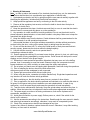
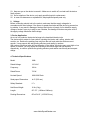
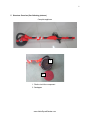
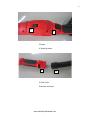
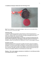
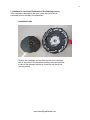
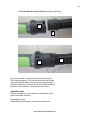
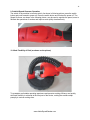
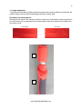
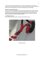
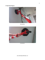
1 INSTRUCTION MANUAL ALEKO® Drywall Sander MODEL: 690L READ THROUGH CAREFULLY AND UNDERSTAND THESE INSTRUCTIONS BEFORE USE ! Visit our web site for more great products, parts and accessories: www.AlekoDrywallSander.com 2 Contents 1. Warning & Statements 3-4 2. Voltage 4 3. Device Application 4 4. Technical Specifications 4 5. Structure Overview 5-7 6. Installation & Sandpaper Replacement 8 7. Installation & viscid disc Replacement 9 8. Connection Set for Dust Outlet 10 9. Switch& Speed Governor operation 11 10. Work Flexibility of Disk 11 11. Length adjustment 12 12. Adjustment of suction power 13 13. LED light(Optional) 14 14. Application Diagram 15 15. Cleaning 16 16. Replacement of carbon brush 17 www.AlekoDrywallSander.com 3 1.Warning & Statements Note:In order to reduce the hazards of fire, electrical shock and injury, etc, the statements listed below shall be taken into consideration upon application of electric tools. 1. Understand your electric tool fully by going through the user manual carefully together with identifying the application, limitation and potential risk accordingly. 2. Adopt protective appliances and act by conforming to the due order strictly. 3. Remove all the regulatory instruments, and form the habit to check about that prior to application of electric tools. 4. Keep the operational site clean. Accidents are most likely to occur in case that the electric tools are used in a messy and dirty place, or on the workbench. 5. Any operation in unsafe conditions is strictly prohibited. Do not use the electric tools in places exposed to damp/moisture, or leave them outside in rainy days. Make sure to keep the operational site bright enough. 6. Keep the children away from the devices. Certain distance shall be guaranteed as for the children in search of on-site operational experience. 7. Actions shall be taken to avoid the workshop accessible by children without permission, such as locking the door, cutting off the power supply or taking away the launch key. 8. Do not use the devices at will. To ensure the overall quality of work piece and maintain security anyway, please use the devices within the design capacity. 9. Use the devices correctly, and do not operate them in overloading or abnormal status. 10.Ensure appropriate clothing. Do not wear loosen clothes, gloves, tie, knot, etc. which may result in hazards of being entangled by running devices. Prefer shoes with skid proof to avoid slipping, and cut the hair to the proper length. 11.Remember to wear protective spectacles. Abundant dust may come out in the buffing process, thus it’s necessary to wear dust mask. Glasses in daily use incorporate lens with impact resistance only, which could by no means meet the safety requirements. 12.Do not place your hands over the twisting disk. Meanwhile, stand still during the operations. 13.Prior to adopting the device, check if the disk suffers from defects as rupture and the sandpaper is well-composed. 14.Ensure tight connections at the disk and other joints. 15.When using the device, remember to hold the handle firmly. Single-hand operations and any intentions to touch the disk are strictly prohibited. 16.Before switching on, the disk shall be away from any contact of other objects. 17.Prior to application, the device shall be powered and switched on to make the disk twist at full speed. Avoid waver arising from installation error and misplaced disk. In case of any malfunction, cut off the power supply and cease the operations at hand immediately. 18.Treat the device maintenance cautiously. Keep the grinder sharp and safe at any time. In addition, follow the instructions to lubricate the device and replace appropriate accessories. 19.The power supply must be cut off during maintenance, such as the replacement of accessories, sandpaper, etc. 20.Avoid direct connection to power supply. Before power on, check if the switch for the device is off in advance. 21.Use the accessories according to the instructions. Read through the user manual in details, and select right accessories accordingly, otherwise, it may result in unexpected injuries. 22.Check if the components or devices are damaged at any time. In case of any failure or abrasion, replace the device at once. Otherwise, it may affect working efficiency or even result in accidents. www.AlekoDrywallSander.com 4 23.Keep an eye on the device to cancel it. Make sure to switch off, and wait until the device finally ceases. 24.As for adoption of the device, only apply specified parts for replacement. 25.In case of maintenance or replacement, adopt specified spare parts only. 2. Voltage Before connecting electric tool to the socket, make sure that the supply voltage be in accordance with rated voltage. If the former is greater than latter and the device is powered on by mistake, it may result in damage of devices and injuries of people. As for indefinite supply voltage of socket, never try to plug for use. Besides, the damage of devices may also occur if the supply voltage falls below rated voltage. 3. Device Application As one of our products, the device belongs to the hand-held electric tools. The device mainly caters for lime surface, including the interior wall, ceiling, exterior wall, corridor, etc. Remove the painting lime mud from the wall, and make the surface even or smooth. It may promote the wall grinding efficiency and quality by workers. With various conditions taken into consideration in the design, the device may run at high or low speed. In addition, you may adjust the connection structure at high and low locations respectively, in order to optimize the grinding efficiency and realize user-friendly and compact design. 4. Technical Specifications Model: 690L Rated Voltage: 110 V AC Frequency: 60 Hz Rated Power: 710 W No-load Speed: 800-1600 R/min Sand-paper Dimensions: Ф 9" (225 mm) Safety Standard: II /ˇ□ Net/Gross Weight: 10 Lb (5 kg) Length: 56"/ 76" (1420mm/1940mm) Packing Dimensions: 60"x10"x12" (153*26*29 cm) www.AlekoDrywallSander.com 5 5.Structure Overview (See following pictures) Complete appliance 1 2 1. Plastic viscid disc component 2. Sandpaper www.AlekoDrywallSander.com 6 4 3 3.Switch 4. Speed governor 5 6 5. Dust Outlet 6.Vacuum dust hose www.AlekoDrywallSander.com 7 7 7. Locking nut 1. Plastic viscid disc component 2. Sandpaper 3. Switch 4. Speed governor 5. Dust Outlet 6. Vacuum dust hose 7. Locking nut Standard Accessories Sandpaper: 6pcs Allen Wrench: 1pcs Carbon Brush: 2pcs Telescopic Dust hose: 5FT(1.5 m)/1pcs Multi-blade Screwdriver: 1pcs www.AlekoDrywallSander.com 8 6. Installation & Sandpaper Replacement (See following picture) Note: Prior to installation or removing the sandpaper, make sure to not only switch off the device, but also cut off the power supply. Installation Guide To ensure the replacement procedures, place the device on the smooth ground prior to installation. Take the sandpaper from the toolbox, and then fix it onto the disk (see Fig .2). The back of the sandpaper (Item 1) will automatically glue with the disk/adhesive disk (Item 2), making both connection and conduction available. In order to promote the grinding efficiency, it is necessary to change the sandpaper after the device has been operational for a certain period. Firstly, switch off the device and disconnect the socket. Then, remove the previous sandpaper entirely from the disk, so as to lay new sandpaper neatly as well as facilitate future replacement. At last, fix new sandpaper in position. Sandpaper Overview Grinding towards the target wall and object is possible with abrasive grains and sandpaper twisting upon operations. The sandpaper is classified into various categories according to its dimensions. It is recommended to select the sandpaper in accordance with actual size of the disk. The more abrasive grains included on the sandpaper, the better flatness and parallelism can be achieved via grinding, while the grinding efficiency will fall accordingly and vice versa. Therefore, the sandpaper (Ф225mm) is recommended upon actual needs. Warning : Prior to the sandpaper replacement or installation, do read safety precautions and installation guide carefully. www.AlekoDrywallSander.com 9 7. Installation & viscid disc Replacement (See following picture) If the viscid disc is damaged in the work, a new viscid disc can be purchased from our company for replacement. Installation Guide Remove the sandpaper, put the Allen wrench into the hexagon hole in the center of the viscid disc and then rotate anticlockwise to take off the damaged viscid disc. Install the new viscid disc (see the picture). www.AlekoDrywallSander.com 10 8. Connection Set for Dust Outlet (See following pictures) A B B A As its name implies, it is used for connecting the device to Dust Outlet (accessory). The dust will come out from the wall upon operating the grinder. The device is connected to Dust Collector at back via Connection Set for Dust Outlet, making it possible for the operator to reduce the amount of dust. Installation Guide Plug the component b into component, make the lock in the groove and rotate clockwise. Dismantling Process Rotate the lock anticlockwise and pull out the dust hose www.AlekoDrywallSander.com 11 9. Switch& Speed Governor Operation The switch of the machine is two step switch. As shown in following picture, press the switch button and push forward to power on. Press the switch button and turn back to power off. The Speed Governor, as shown in the following picture, may be used to regulate the speed, so as to facilitate the operations of workers and improve work quality simultaneously. 10. Work Flexibility of Disk (as shown on the picture) To guarantee comfortable operating experience and promote working efficiency and quality, structural flexibility is achieved at the front part of the device, making the workers adapt promptly to various working sites. www.AlekoDrywallSander.com 12 11. Length adjustment To guarantee comfortable operating experience and promote working efficiency and quality, the machine length could be adjusted according to different working sited. Procedures for the adjustment: According to the mark on the machine: rotate the Locking nut anticlockwise (rotate component A to unlock mark), pull out component B to needed length, rotate the component A clockwise (the lock mark) to lock. Unlock mark Lock mark A B www.AlekoDrywallSander.com 13 12. Adjustment of suction power Main control knob Assistant control knob www.AlekoDrywallSander.com 14 In order to save the worker’s physical labor, this machine is designed with suction power to reduce the machine gravity. When connect to vacuum cleaner, the suction system will make the machine suck on the drywall wall, the operator can adjust the suction accordingly. Guide for the suction adjustment: The main control knob and assistant control knob both can adjust the suction. When the main control knob fix in a certain position you can use the assistant control knob to adjust. It’s better to put the main control knob in the max position at first then adjust the suction by assistant control knob. The main control knob would be needed only when the assistant control knob, even in max position, still could not reach your demand. 13. LED light (Optional) When working in the dusky condition, LED light could beadded for help. LED light (optional) www.AlekoDrywallSander.com 15 14. Application Diagram High position Low position www.AlekoDrywallSander.com 16 Ceiling position As shown on the picture the operator can sanding the different position of the wall. 15. Cleaning Regular cleaning shall be conducted after grinding. Cleaning the devices frequently may help to extend operatinglife and reduce repair rate. It is recommended to clean the connection sets and components of electric motor without application of water. Timely cleaning is recommended after the application of the devices. Clean the devices with a hairbrush and a piece of dry cloth, or simply blow it with high pressure gas. www.AlekoDrywallSander.com 17 16. Replacement of carbon brush When the original carbon brush is worn the machine has a set spare carbon brush for replacement. Guide for the replacement of carbon brush : 1)Use the screwdriver to open the cover of the carbon brush and take out the carbon brush 2)Put the spare carbon brush into the Brush Carrier, use the screwdriver to rotate and fix the cover of carbon brush tightly. Carbon brush replacement position Visit our web site for more great products, parts and accessories: www.AlekoDrywallSander.com