1
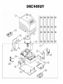
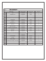
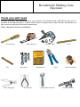
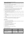
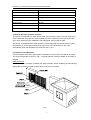
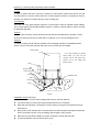
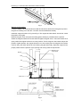
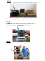
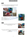
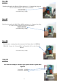
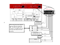
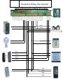
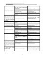
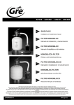
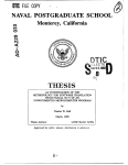
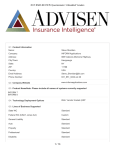
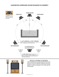
Sliding Gate Operator
User's Manual
Lockmaster DKC400UY
Lockmaster DKC400U
Aleko AR1400
www.Openers4less.com
[email protected]
352.241.8259
DKC400 (U) Y SLIDING GATE OPERATOR USER’S MANUAL
OUTLINE
1. Important safety information…………………………3
2. Main features ………………………………………3
3. Main technical parameters …………………………3
4. Working principle and main structure ………………4
5. Installation and adjustment …………………………4
6. Connecting …………………………………………7
7. Control ……………………………………………10
8. Check
……………………………………………14
9. Maintenance ………………………………………14
10. Troubleshooting …………………………………15
2
DKC400UY
MODEL:
DKC400UY
COMPONENT
DESCRIPTION
COMPONENT
MANUFACTURER
MFR’S PART NO.
QUANTITY
1
Cover
LockMaster
tr3cov1
1
2
Set Phillips screw
LockMaster
tr3sps2
1
3
½ h.p. Motor
LockMaster
tr3mot3
1
4
Limit magnets
LockMaster
tr3lm4
2
5
Control board
LockMaster
tr3c/b5
1
6
Capacitor
LockMaster
tr3cap6
1
7
Gear racks 2.3 ft.
LockMaster
tr3gr7
5
8
Plastic clip
LockMaster
tr3pc8
4
9
Base plate for receiver/
limit switch sensor
LockMaster
tr3bp9
1
10
Base plate for control board
LockMaster
tr3bp10
1
11
Plastic clip
LockMaster
tr3pc11
4
12
Receiver
LockMaster
tr3rec12
1
13
Large bracket for magnet (open limit)
LockMaster
tr3lbol13
1
14
Limit switch sensor
LockMaster
tr3ls14
1
15
19 tooth Sprocket
LockMaster
tr319spr15
1
16
C-Clamp
LockMaster
tr3ccl16
1
17
Motor housing
LockMaster
tr3mh17
1
18
Small bracket for magnet (close limit)
LockMaster
tr3sbcl18
1
19
Mounting base
LockMaster
tr3mb19
1
20
Manual release keys
LockMaster
tr3keys20
2
Residential Sliding Gate
Operator
Tools you will need
During assembly and installation of your opener, the instructions will call for the use of
various tools shown below. Other tools may be required as needed for the installation of
the concrete pad and electrical connection.
Table 3 Required Tools for Installation
Screwdriver
File
Wire Strippers
Tape Measure
Wrenches
Wire Cutter
Electric Drill
Multimeter
Pliers
Adjustable Wrench
Level
Allen Wrenches
Socket Wrench
DKC400 (U) Y SLIDING GATE OPERATOR USER’S MANUAL
1. Important safety information
Carefully read and follow all safety precaution and warnings before attempting to install and use
this operator, incorrect installation can lead to severe injury.
The gate operator should be installed by a qualified technician; otherwise, serious personal
injury or property damage may occur.
The auto-reverse function must be checked during installation to ensure that the gate can
auto-reverse in the event of obstruction.
This auto-reverse function should be regularly inspected and adjusted, if necessary.
When opening or closing the gate, do not attempt to walk or drive through the gate.
Children should not be allowed to play near or operate automatic gates.
The automatic gate operator must be grounded.
Install the gate operator on the inside of the property, DO NOT install it on the outside of
the property where the public has access to it.
Be careful when in close proximity to moving parts where hands or fingers could be
pinched.
Do not allow control devices to be placed so that a person can access them by reaching
through the gate.
In the event of power failure, an emergency release key allows you to operate the gate
manually.
The operator should be switched off before repairing it or opening its cover.
Please erase and reprogram the code after installing the operator.
2. Main features
The device is used to drive sliding gate.
For your safety, the DKC400 (U) Y will stop and reverse if it was obstructed on closing and
stop when it was obstructed on opening.
Supports up to 100 remote controls.
User programmable and user erasable remote codes.
Infrared terminal (N.C) is supplied to use.
Auto-close feature is available for this operator.
Pedestrian mode.
Manual key release design for emergency purposes.
3. Main technical parameters
Type
DKC400Y
DKC400UY
Power supply:
AC 220V, 50Hz
AC110V, 60Hz
Motor speed
1400 r/min
1680 r/min
14m/min (24 teeth)
17 m/min (24 teeth)
11m/min (19 teeth)
13m/min (19 teeth)
Gate moving speed
Output torque
14N·m
3
DKC400 (U) Y SLIDING GATE OPERATOR USER’S MANUAL
Limit switch
Magnetic limit switch
Remote control operating range
30m
Frequency
433.92mHz
Remote control mode
Single-button
Auto-close time
0-44 sec.
Working time
90 sec.
Noise
≤62dB
Environmental temperature
-10ºC~+55ºC
4. Working principle and main structure
The device is composed of a single-phase motor, worm and worm gear. The main shaft of the
motor rotates the worm with the clutch engaged, the worm rotates the worm gear and output
gear, which pushes the rack attached to the sliding gate, thus moving the gate.
The device is installed with a thermal protector, the thermal protector will switch off the motor
automatically in case of the temperature is higher than 120°C and switch on the motor
automatically when the temperature is lower than 85°C±5°C.
5. Installation and adjustment
The DKC400(U)Y rack-driven gate operator operates by forcing a drive rack past a drive gear.
The entire configuration is shown in Fig.1. The gate operator must be installed on the inside of
the gate.
Gate preparation
Be sure the gate is properly installed and slides smoothly before installing the DKC400(U)Y
sliding gate operator. The gate must be plumb, level, and move freely.
Fig.1
4
DKC400 (U) Y SLIDING GATE OPERATOR USER’S MANUAL
Conduit
In order to protect the wires, use PVC conduit for control wires, conduit must be set into the
concrete when it is poured. Wires within the conduit shall be located or protected so that no
damage can result from contact with any rough or sharp part.
Concrete pad
The base unit of the gate operator requires a concrete pad in order to maintain proper stability.
The concrete pad should be approximately 300mm x 200mm x 200mm deep in order to provide
for adequate operation.
Anchors
You can use the anchors, bolts, washers and nuts that are provided with the operator. These
anchors must be set into the concrete when it is poured, or you can use wedge anchors.
Operator
In locations where ground freeze is possible, mount the gate operator on installation pad as
shown in Fig.2. Check the operator and make sure it is lined up with the gate.
Gate operator
﹡ If you have installed an external
button switch, you must use two
conduits: one for main power wire,
another one for low voltage wire
(button switch).
Gear
Nut
Spring washer
Plain washer
Nut
Anchor
Installation pad
Bolt
Conduit
Wires
Fig.2
Installation of rack (see Fig.3)
Fix the three nuts (in the same package with rack) on the rack element.
Lay the first piece of rack on the gear and weld the first nut on the gate.
Move the gate manually, checking if the rack is resting on the gear, and weld the second
and third nut.
Bring another rack element near to the previous one. Move the gate manually and weld the
three nuts as the first rack, thus proceeding until the gate is fully covered.
When the rack has been installed, to ensure it meshes correctly with the gear.
The space between rack and gear is about 1mm.
5
DKC400 (U) Y SLIDING GATE OPERATOR USER’S MANUAL
Fig.3
Magnets for limit switch
To ensure safety, it is recommended to install limit devices at both ends of the gate to prevent
the gate from sliding out of the rails. The rails must be installed horizontally.
Install the magnet as shown in Fig.4 and Fig.5. The magnet and limit switch are used to control
the position of the gate.
Release the gear clutch and push the sliding gate manually to pre-determine the position.
Solder the magnet bracket to the rack and then tighten the gear clutch. The lower bracket is for
open position and higher bracket is for close position. Fix the magnet to the bracket. Adjust the
position of gate operator, the magnet should be 10~15mm away from the magnetic limit switch,
if too far away, the switch will fail to work. Moving the gate electrically, adjust the magnet to the
proper position until the position of the opening and closing meet the requirement.
10-15mm
Magnetic limit
switch inside
Magnet
Gate
Nut
122mm
Rack
Gear
Guide rail
Fig.4
Fig.5
6
Step #1
Unscrew the Blue Cover from the Motor and set it aside.
Open the small white box & make sure that the contents include:
(1) - Receiver and (1) - Control Board
Step #2
Install the Control Board onto the Motor by mounting it on the
small white clips that are on the large Mounting Plate.
(as shown below)
Step #3
Install the Receiver onto the Motor by mounting it on the small
white clips that are on the small Mounting Plate.
(as shown below)
7
MAKING THE CONNECTION
Step #4
Now you will begin the installation by screwing the wires that are coming
from the small Receiver Board onto the Terminals (see Pic 1, right) from
the Control Board, in the following order:
Terminal 10 - GREEN WIRE
Terminal 11 - RED WIRE
Terminal 12 - YELLOW WIRE (any)
Terminal 13 - YELLOW & BLUE WIRE (any )
Terminal 14 - BLUE WIRE (any)
Pic 1
Step #5
Next, take the set of wires coming from the motor and connect the
red and black wires anywhere onto the plug.
(as shown on the pic, right)
Once you have connected those wires, you will then take that plug
and connect it to the Control Board on the section labeled:
"MOTOR"
(as shown on the pic, right)
8
Step #6
Find the plug with the Blue & Yellow wires on it. Connect the plug on
to the Control Board on the section labeled:
"CAPACITOR"
(as shown on the pic, right)
Step #7
Find the plug with the Red, White & Blue wires on it. Connect the plug
on to the Control Board on the section labeled:
"LIMIT SWITCH"
(as shown on the pic, right)
Step #8
Find the wire coming from the bottom of the Motor that is GREEN &
YELLOW. Screw the "Ground Wire" to Terminal #22 on the Control
Board
(as shown on the pic, right)
Step #9
You are now ready to connect you power wires to your Gate
Opener!
Terminal #1 - POWER
Terminal #2 - NEUTRAL
9
AC SLIDE GATE CONTROLLER
FEATURE SELECTOR
10
When using auto close features
l one dip
di switch
it h should
h ld be
b
only
ON. The other two dip switch
should be in the OFF position for
the auto close feature to work
correctly.
Limit Switch Type
ON: Normally Close
OFF: Normally Open
Auto Close Feature
12.5 Seconds
DIP 1
DI P 2
DI P 3
25 Seconds
DI P 4
45 Seconds
Direction of Gate
ON: Gate Opening to the left
OFF: Gate Opening to the Right
DI P 5
DI P 6
NOT USED
Receiver
Channel One (not used at this time)
Channel Two (not used at this time)
DI P 7
DI P 8
Transmitter/Remote Control (shown in Figure 9)
1.
2.
3.
4.
5.
6.
7.
8.
Yellow Button Channel
Blue Button Channel
Indicator Light
Yellow Button Channel – exposed
DIP Switch
Battery
Blue Button Channel – exposed
Back side cover
Figure 9
Receiver
1. Channel 1 DIP Switch (yellow
button on remote control
transmitter)
2. Channel 2 Dip Switch
(Secondary, Multi-Code
compatible, blue button on
remote control transmitter)
Figure 10
The red and black wires are 24 volt
power input. The two yellow are the
channel 1, the two white are
channel 2, and the black wire is the
antenna wire
Figure 10
Setting the Transmitter DIP Switches:
There are a total of eight (8) transmitter DIP switches. Each one can be placed in three (3) different positions
(+, 0, -). DO NOT set all of the switches to the same position, for example: all +, all 0 or all -. Once the
DIP switches have been set to a personal code, replace and close the cover.
11
Residential Sliding Gate Operator
Optional Equipment Installation Procedures
O
O
O
O
Green
Brown
Red
Black
O
O
Blue
Brown
O
O
O
O
Black
White
O
O
Grey
Grey
Black
Black
DKC400 (U) Y SLIDING GATE OPERATOR USER’S MANUAL
10. Troubleshooting
Trouble
Possible causes
The wire connector terminal block
becomes loose.
Motor only runs in one direction.
The limit switch wire connector terminal
block becomes loose.
The electric component on the control
board such as Q2, Q91 or Q92 may be
damaged.
By pressing button 1(button 2 or
button 3) which has been
programmed to open the gate,
press the same button again to
stop the gate in required position,
but the gate will auto-close
immediately.
When you use button 4 of remote
control to open the gate, gate
travels too short.
When you use button 4 of remote
control to open the gate, but the
gate will auto-close immediately.
The gate will not open or close.
Remote control does not work
When you open the gate by using
button 1(button 2 or button 3)
which has been programmed, gate
will stop in mid-travel or reverse
before reaching the fully limit
position.
The auto-close time is too short.
Solutions
Check wire connector terminal block
make sure it is plugged in terminal
block 10, X8.
Check limit switch wire connector
terminal block make sure it is plugged
in terminal block 9, X9.
Check the limit switch mode.
Replace the electric component Q2,
Q91 or Q92 (BTA16/600) or replace the
board.
Reset the auto-close time. See Set
auto-close function section.
The limit switch wire connector terminal
block becomes loose.
Connecting wires or terminal blocks are
too loose.
The electric component on the control
board such as Q2, Q91 or Q92 may be
damaged.
Reset the width of pedestrian mode.
See Set width of pedestrian mode
section.
Reset the auto-close time of pedestrian.
See Set auto-close function of
pedestrian mode section.
Check the limit switch mode (see table
1 DIP-switch).
Check the connecting wires and
terminal blocks.
Replace the electric component Q2,
Q91 or Q92 (BTA16/600) or replace the
board.
Power switch is OFF
Make sure power switch is ON.
The indicator light of remote control
does not light.
Check the batteries on your remote
control
After making sure the codes are
correct, erase remote controls and then
re-program the codes in the device.
See Adding extra remote controls
(learning) section.
The width of pedestrian mode is too
narrow.
The auto-close time of pedestrian mode
is too short.
Remote control is not suitable for
receiver.
Broken receive board
Replace receive board.
The Force Adj. (VR1) is adjusted too
small.
Check the Force Adj. (VR1). Adjust VR1
to increase force.
Gate is obstructed.
Remove the obstruction.
Link a new antenna (1~1.2m BVR
The
remote
control
distance is too short.
operating
0.75mm2) to the old antenna. Then fix
Signals are shielded by the gate.
the antenna on the wall vertically, make
sure the total height from the top of
antenna to the ground is approx. 1.5m.
15
[email protected]
www.Openers4Less.com
©2005-2009 LockMaster All Rights Reserved