1
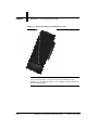
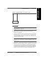
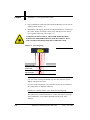
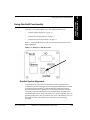
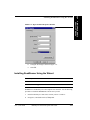
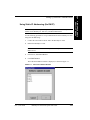
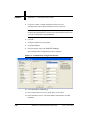
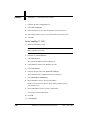
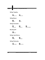
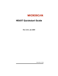
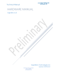
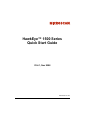
HawkEye™ 1500 Series
Quick Start Guide
V2.4.1, Nov 2008
EM-40390-1V241
Copyright and Disclaimer
Copyright ©2008 by Microscan Systems, Inc.
1201 S.W. 7th Street, Renton, WA, U.S.A. 98057
(425) 226-5700 FAX: (425) 226-8682
All rights reserved. The information contained herein is proprietary and is provided solely for the purpose of allowing
customers to operate and/or service Microscan manufactured equipment and is not to be released, reproduced, or used
for any other purpose without written permission of Microscan.
Throughout this manual, trademarked names might be used. Rather than place a trademark (™) symbol at every
occurrence of a trademarked name, we state herein that we are using the names only in an editorial fashion, and to the
benefit of the trademark owner, with no intention of infringement.
Disclaimer
The information and specifications described in this manual are subject to change without notice.
Latest Manual Version
For the latest version of this manual, see the Download Center on our web site at: www.microscan.com.
Technical Support
For technical support, email: [email protected].
Microscan Systems, Inc.
1201 S.W. 7th Street
Renton, WA 98057
U.S.A.
Tel: 425 226 5700
Fax: 425 226 8250
[email protected]
Microscan Europe
Tel: 31 172 423360
Fax: 31 172 423366
Microscan Asia Pacific
R.O. Tel: 65 6846 1214
Fax: 65 6846 4641
Microscan Limited Warranty Statement and Exclusions
What Is Covered?
Microscan Systems Inc. warrants to the original purchaser that products manufactured by it will be free from defects in
material and workmanship under normal use and service for a period of one year from the date of shipment. This
warranty is specifically limited to, at Microscan’s sole option, repair or replacement with a functionally equivalent unit
and return without charge for service or return freight.
What Is Excluded?
This limited warranty specifically excludes the following: (1) Any products or parts that have been subject to misuse,
neglect, accident, unauthorized repair, improper installation, or abnormal conditions or operations; (2) Any products or
parts that have been transferred by the original purchaser; (3) Customer mis-adjustment of settings contrary to the
procedure described in the Microscan Systems Inc. owners manual; (4) Upgrading software versions at customer request
unless required to meet specifications in effect at the time of purchase; (5) Units returned and found to have no failure
will be excluded; (6) Claims for damage in transit are to be directed to the freight carrier upon receipt. Any use of the
product is at purchaser’s own risk. This limited warranty is the only warranty provided by Microscan Systems Inc.
regarding the product. Except for the limited warranty above, the product is provided “as is.” To the maximum extent
permitted by law, this express warranty excludes all other warranties, express or implied, including but not limited to,
implied warranties of merchantability and. Technical support questions may be directed to: [email protected]
Register your product with Microscan: www.microscan.com/register fitness for a particular purpose. Microscan Systems
Inc. does not warrant that the functions contained in the product will meet any requirements or needs purchaser may
have, or that the product will operate error free, or in an uninterrupted fashion, or that any defects or errors in the product
will be corrected, or that the product is compatible with any particular machinery.
Limitation of Liability
In no event shall Microscan Systems Inc. be liable to you or any third party for any special, incidental, or consequential
damages (including, without limitation, indirect, special, punitive, or exemplary damages for loss of business, loss of
profits, business interruption, or loss of business information), whether in contract, tort, or otherwise, even if Microscan
Systems Inc. has been advised of the possibility of such damages. Microscan Systems Inc.’s aggregate liability with
respect to its obligations under this warranty or otherwise with respect to the product and documentation or otherwise
shall not exceed the amount paid by you for the product and documentation. Some jurisdictions do not allow the
exclusion or limitation of incidental or consequential damages or limitations on an implied warranty, so the above
limitation or exclusion may not apply to you. This warranty gives you specific legal rights, and you may also have other
rights which may vary from state to state.
Tel: 425.226.5700 | Fax: 425.226.8250 | [email protected]
Contents
PREFACE
Welcome!
vii
Purpose of This Manual vii
Manual Conventions vii
CHAPTER 1
HawkEye™ 1500 Quick Start Guide
Package Contents 1-1
Recommended Configuration 1-3
Getting the HawkEye™ Up and Running
Using QuicSet® Functionality 1-7
1-1
1-3
QuicSet Symbol Alignment 1-7
QuicSet Decoder Optimization 1-9
QuicSet Decoder Factory Defaults 1-9
QuicSet Summary 1-10
Setting Up RS-232 Communications 1-10
Installing ReadRunner Using the Wizard 1-11
Setting Up Network Communications 1-12
Using DHCP 1-12
Using Static IP Addressing (No DHCP) 1-13
Using an Ethernet Cross-Link Cable 1-15
Windows 2000 1-15
On the PC... 1-15
On the HawkEye™ 1500... 1-16
Windows XP 1-17
On the PC... 1-17
V2.4.1, Nov 2008
HawkEye™ 1500 Series Quick Start Guide
v
Contents
On the HawkEye™ 1500... 1-18
Sample Data Matrix Symbols & Barcodes 1-19
Reader Programming Through Data Matrix 1-19
Setting Serial Communications 1-19
Setting Triggers 1-19
Resetting 1-19
Setting Targeting 1-20
Setting Beeper 1-20
Setting Illumination 1-20
Resetting ROI 1-20
Setting Learn/Unlearn 1-20
Setting Photometry 1-20
Saving 1-21
Setting DHCP 1-21
For Detailed Information
vi
1-21
HawkEye™ 1500 Series Quick Start Guide
V2.4.1, Nov 2008
Preface
Welcome!
PREFACE
Purpose of This Manual
The purpose of the manual is to get you up and running quickly and confidently
with your HawkEye™ 1500.
Manual Conventions
The following typographical conventions are used throughout this manual.
V2.4.1, Nov 2008
•
Items emphasizing important information is bolded.
•
Menu selections, menu items and entries in screen images are indicated as:
Run (triggered), Modify..., etc.
HawkEye™ 1500 Series Quick Start Guide
vii
Preface
viii
HawkEye™ 1500 Series Quick Start Guide
V2.4.1, Nov 2008
1
HawkEye™ 1500
Quick Start Guide
1
HawkEye™ 1500 Quick Start
Guide
CHAPTER 1
The Quick Start Guide contains step by step procedural information to set up the
Microscan HawkEye™ 1500 series camera. The camera can read both 1-D
barcode and 2-D Data Matrix symbologies, and uses patented image lighting,
capturing and decoding to read Data Matrix direct part marks created with laser
etch, dot peening, ink-jet, chemical etch, casting, and other techniques on a
variety of surfaces.
Package Contents
Please take a moment to confirm that the package contains the following items,
as shown in Figure 1–1:
V2.4.1, Nov 2008
•
CD (contains software and documentation)
•
HawkEye™ 1500 smart camera (1515 shown in Figure 1–1)
•
Serial communications cable
•
Power supply with international plug adapters (optional accessory)
HawkEye™ 1500 Series Quick Start Guide
1-1
Chapter
1
HawkEye™ 1500 Quick Start Guide
FIGURE 1–1.
Package Contents
HawkEye 1515
Serial Communications Cable
Power Supply with International Plug Adapters
(Optional)
Note: Newer HawkEye 1515 cameras look different that the camera shown here.
1-2
HawkEye™ 1500 Series Quick Start Guide
V2.4.1, Nov 2008
Recommended Configuration
The minimum recommended system configuration is a PC with a Pentium II 200
MHz and 64MB of memory. This product runs on Windows 2000 (SP 4) and
Windows XP (SP 2).
WARNING! DO NOT LOOK AT THE LASER. WHEN READING
PARTS THAT ARE HIGHLY REFLECTIVE, BE CAREFUL THAT
THE LASER IS NOT REFLECTED INTO SOMEONE’S EYE.
Getting the HawkEye™ Up and Running
At this point, the PC is optional, as the HawkEye™ 1500 will operate in its
default configuration. The PC may be needed later to adjust HawkEye™ 1500
operating parameters to exactly match particular application requirements.
Ultimately, a device such as a PC will be needed to capture the data output sent
by the HawkEye™ during the scanning operation.
Use the following procedure to get your HawkEye™ 1500 up and running:
1.
Carefully remove the HawkEye™ 1500 from its packaging.
2.
For maximum adjustment flexibility, mount the HawkEye™ 1500 on an
adjustable ball swivel type mount (not supplied).
3.
Adjust the HawkEye™ 1500 to a reading angle of approximately 20° off the
symbol’s vertical axis or surface normal.
Surface normal is the axis that is perpendicular to the surface on which the
symbol is located. Visually, you can determine the 20° angle by aligning the
symbol’s surface normal parallel to the top edge of the HawkEye™ 1500
graphic logo that is located on either side of the camera.
This scan angle reduces surface glare and enhances contrast. The angle may
be increased or decreased (± 10°) to optimize read performance on different
symbol surfaces. (See Figure 1–2.)
V2.4.1, Nov 2008
HawkEye™ 1500 Series Quick Start Guide
1-3
1
HawkEye™ 1500
Quick Start Guide
Recommended Configuration
Chapter
1
HawkEye™ 1500 Quick Start Guide
FIGURE 1–2.
Optimal Mounting for the HawkEye™ 1515
Note: 20° (dotted line is vertical) is the correct angle for the HawkEye™
1515, as shown in Figure 1–2. However, due to the robustness of the
algorithm, you can adjust the camera ± 10° to optimize read performance on
different symbol surfaces.
1-4
HawkEye™ 1500 Series Quick Start Guide
V2.4.1, Nov 2008
FIGURE 1–3.
Optimal Mounting for the HawkEye™ 1525
Note: The HawkEye™ 1525 should be mounted perpendicular to the symbol
being read, as shown in Figure 1–3.
4.
Connect the power cord to the outlet and to the rear panel of the
HawkEye™ 1500 (DC-IN).
Apply power and listen for three beeps at the end of the boot-up cycle, which
takes approximately 15 seconds. Once the HawkEye™ completes its boot
cycle, it is operational, and ready to read symbols. This is indicated by the
yellow Mode indicator being on.
Note: By default, the HawkEye™ 1500 ships with DHCP enabled. If the
HawkEye™ 1500 is not connected to a network with DHCP, it will time out
after 15 seconds.
The HawkEye™ 1500’s default configuration is called Demo mode, which
allows easy operation and testing, as it does not require any external signals
to operate. In Demo mode, the HawkEye™ 1500 is programmed to keep
both lighting and laser targeting permanently on. It also scans continuously
for symbols (continuous internal trigger), while automatically adjusting the
Photometry parameters (Exposure and Gain) to their optimum settings.
V2.4.1, Nov 2008
HawkEye™ 1500 Series Quick Start Guide
1
HawkEye™ 1500
Quick Start Guide
Getting the HawkEye™ Up and Running
1-5
Chapter
1
HawkEye™ 1500 Quick Start Guide
5.
Place a Data Matrix or Barcode symbol under the HawkEye™ 1500. See the
sample symbols on page 1–19.
6.
Establish the read range by physically moving the HawkEye™ 1500 toward
the symbol, starting from about 6 inches away, until the two laser dots are
close together on the symbol. See Figure 1–4.
WARNING! DO NOT LOOK AT THE LASER. WHEN READING
PARTS THAT ARE HIGHLY REFLECTIVE, BE CAREFUL THAT
THE LASER IS NOT REFLECTED INTO SOMEONE’S EYE.
FIGURE 1–4.
Laser Targeting
NEAR FOCUS LIMIT
FOCUS PLANE
FAR FOCUS LIMIT
Note: The point where the laser dots converge is when the HawkEye™ 1500
is at “near focus.” Moving the HawkEye™ 1500 away from the symbol
slightly will improve the focus.
If you are using a HawkEye™ 1515, remember to keep the 20° tilt angle to
the symbol surface to eliminate reflections.
HawkEye™ 1510 and 1500 XL series do not have laser targeting.
The symbol is now within the HawkEye™ 1500’s read range. A good read
will be indicated by a beep and the illumination of the green “Pass”
indicator.
1-6
HawkEye™ 1500 Series Quick Start Guide
V2.4.1, Nov 2008
Using QuicSet® Functionality
The HawkEye™ 1500’s QuicSet® functions help you set up the camera without
the need for an external program or PC. The QuicSet® functions are:
•
“QuicSet Symbol Alignment” on page 1-7
•
“QuicSet Decoder Optimization” on page 1-9
•
“QuicSet Decoder Factory Defaults” on page 1-9
Figure 1–5 shows the HawkEye™ 1500 rear panel with the QuicSet recessed
button highlighted.
FIGURE 1–5.
HawkEye™ 1500 Rear Panel
QuicSet Symbol Alignment
In its default mode of operation, the HawkEye™ 1500 is programmed in a
continuous read mode (non triggered) with targeting and illumination constantly
on. In this mode, the HawkEye™ 1500 automatically adjusts the Gain and
Exposure parameters to the optimal level for the part that is within its field of
view. This is called Auto Photometry. The Auto Photometry algorithm works
with the data that is in the center of the field of view (FOV). Therefore, place the
part that is being read as close as possible to the center of the FOV. To aid you in
the alignment of the symbol in the center of the FOV, use the following
procedure:
V2.4.1, Nov 2008
HawkEye™ 1500 Series Quick Start Guide
1-7
1
HawkEye™ 1500
Quick Start Guide
Using QuicSet® Functionality
Chapter
1
1.
HawkEye™ 1500 Quick Start Guide
Insert a paper clip into the hole marked QuicSet, and press once (see
Figure 1–5).
Ensure that the yellow Mode light is flashing. Physically position the
HawkEye™ 1500 until the laser dots are almost together for small Data
Matrix symbols, or slightly farther apart on the horizontal axis for bar code
symbols.
Note: The HawkEye™ 1500 XL can still benefit from QuicSet alignment.
Alignment and focus must be performed manually!
WARNING! DO NOT LOOK AT THE LASER. WHEN READING
PARTS THAT ARE HIGHLY REFLECTIVE, BE CAREFUL THAT
THE LASER IS NOT REFLECTED INTO SOMEONE’S EYE.
When the laser beams are centered on the symbol, a series of beeps will be
heard. The beeps have three tones and three rates:
–
Low — Signals that the symbol is in the field of view
–
Middle — Signals that the symbol is close to optimal read position
–
High — Signals the optimal position
The three LEDs above the blinking Mode LED correspond to the three
beeps.
2.
1-8
–
With poor alignment, there are no LEDs flashing and there is no
beeping.
–
As the alignment improves, the LEDs begin to illuminate, from bottom
to top, and beeping begins.
–
At optimal alignment, all the LEDs are flashing and beeping is at its
highest intensity.
Slightly move the HawkEye™ 1500 until the high intensity beep is
achieved, lock down the camera’s position, then press the QuicSet® button
once to exit QuicSet® mode.
HawkEye™ 1500 Series Quick Start Guide
V2.4.1, Nov 2008
You will hear three short beeps and the Mode LED will return to steady on.
This indicates that the HawkEye™ 1500 is ready to read using the QuicSet®
mode settings.
QuicSet Decoder Optimization
When the HawkEye™ 1500 is set up on a line to read one specific type of mark,
the Decode algorithm can be optimized to look for symbols of the same type and
size. By optimizing the Decode algorithm, the part will be read more reliably
and, in most cases, more quickly.
To optimize the decoder using QuicSet® while in continuous trigger mode,
follow this procedure:
1.
Insert a paper clip into the hole marked QuicSet and press twice (see
Figure 1–5). The HawkEye™ 1500 learns the symbol, which can be verified
by the green LED and one quick beep. You can verify the learn by placing a
different symbol in front of the HawkEye™ 1500, at which time the Fail
light will come on.
QuicSet Decoder Factory Defaults
When the HawkEye™ 1500 needs to read a different part or a variety of parts,
you need to “open up” the Decoder to read the different parts and symbols. These
are the factory default settings for the HawkEye™ 1500. If the Decoder has
previously been optimized, simply:
1.
Insert a paper clip into the hole marked QuicSet and press and hold it for 3
to 4 seconds (see Figure 1–5). You will hear a short beep.
Now the HawkEye™ will read a variety of parts of differing sizes and
symbology types.
Note: The equivalent remote command is RESET FACTORY. For more
information, see the HawkEye™ 1500 Series Reference and Programmers
Manual.
V2.4.1, Nov 2008
HawkEye™ 1500 Series Quick Start Guide
1-9
1
HawkEye™ 1500
Quick Start Guide
Using QuicSet® Functionality
Chapter
1
HawkEye™ 1500 Quick Start Guide
QuicSet Summary
TABLE 1–1. QuicSet®
Summary
QuicSet Button...
To...
Press once
Enter QuicSet Alignment
Press once
Exit QuicSet Alignment
Press twice
Enter QuicSet Decoder Learn
Press and hold for 3 to 4 seconds
Enter QuicSet Decoder Factory
Defaults
Setting Up RS-232 Communications
The HawkEye™ 1500 can communicate using RS-232 serial communications to
a PLC or PC or some other device.
Use the following procedure to set up communications to the device:
1.
Connect the supplied serial cable from the communication device to the
HawkEye™ 1500.
2.
Ensure that the device is set up to communicate at the same RS-232
communication settings as the HawkEye™ 1500.
The default RS-232 communication settings are:
–
Baud rate — 115200
–
Data bits — 8
–
Parity — None
–
Stop bits — 1
–
Flow control — None
For example, to communicate to a PC using HyperTerminal, first start the
HyperTerminal program.
a.
Select File, Properties, Connect To, and Configure.
The HyperTerminal Properties window is displayed, as shown in
Figure 1–6.
1-10
HawkEye™ 1500 Series Quick Start Guide
V2.4.1, Nov 2008
FIGURE 1–6.
HyperTerminal Properties Window
b.
Configure all settings as shown in Figure 1–6.
c.
Click OK.
Installing ReadRunner Using the Wizard
Note: This product runs under Windows 2000 and Windows XP
Note: You must be logged in as Administrator on your PC to install ReadRunner
ReadRunner is the HawkEye™ 1500 Graphical User Interface. Use the following
procedure to install the ReadRunner software onto your PC:
V2.4.1, Nov 2008
1.
Insert the HawkEye™ 1500 Series CD into your PC’s CD drive.
2.
Navigate to, and double click on, Setup.exe.
HawkEye™ 1500 Series Quick Start Guide
1
HawkEye™ 1500
Quick Start Guide
Installing ReadRunner Using the Wizard
1-11
Chapter
1
HawkEye™ 1500 Quick Start Guide
3.
Follow the install wizard and use the suggested option to install the
HawkEye™ 1500 software.
4.
Cycle or reset the power on the HawkEye™ 1500.
The HawkEye™ 1500 is ready for use.
Setting Up Network Communications
When using TCP/IP, the HawkEye™ 1500 can utilize Dynamic Host
Configuration Protocol (RFC2131) for dynamic IP addressing. You can also
configure the camera to use a “static” IP address. If you do not have a network
connection available, you must use RS-232 communications to configure and
control the camera. If you do have a network connection available, please contact
your MIS department to determine if your network uses DHCP addressing. If
your network uses static IP addressing, contact your MIS department to obtain a
unique static IP address for the camera before proceeding.
You can set up communications:
•
“Using DHCP” on page 1-12
•
“Using Static IP Addressing (No DHCP)” on page 1-13
•
“Using an Ethernet Cross-Link Cable” on page 1-15
Using DHCP
Use the following procedure to set up communications on the HawkEye™ 1500
when your network has a DHCP server:
Note: If you are unsure of your network configuration, ask your MIS
administrator.
1.
Connect the Ethernet cable to the HawkEye™ 1500.
2.
Power up the HawkEye™ 1500.
3.
Verify that the ACT and LK LEDs on the back of the HawkEye™ 1500 are
flashing or solid, which indicates Ethernet data activity.
The HawkEye™ 1500 is ready for use.
1-12
HawkEye™ 1500 Series Quick Start Guide
V2.4.1, Nov 2008
Using Static IP Addressing (No DHCP)
Note: Before you can complete this procedure, you must obtain a unique IP
address for the HawkEye™ 1500. See your MIS administrator.
Use the following procedure to set up communications on the HawkEye™ 1500
using static IP addressing.:
1.
Connect the serial cable to the PC and to the HawkEye™ 1500.
2.
Reboot the HawkEye™ 1500.
Note: There will be a 15 second delay as the HawkEye™ 1500 searches for a
DHCP server.
3.
From the PC, launch ReadRunner.
4.
Click Add Camera.
The Add Camera Button window is displayed, as shown in Figure 1–7.
FIGURE 1–7.
V2.4.1, Nov 2008
Add Camera Button Window
HawkEye™ 1500 Series Quick Start Guide
1-13
1
HawkEye™ 1500
Quick Start Guide
Setting Up Network Communications
Chapter
1
5.
HawkEye™ 1500 Quick Start Guide
Click either COM1 or COM2, depending on where the serial
communications cable from the HawkEye™ 1500 is connected.
Note: If you connect using HyperTerminal, the same COM port may not be
reachable through ReadRunner. Disconnect the HyperTerminal connection if
you want to communicate using ReadRunner.
6.
Click OK.
7.
Click the COM button you just added.
8.
Click Take Control.
9.
From the Settings menu, click Serial/TCP Settings.
The Communications Configuration window is displayed.
FIGURE 1–8.
1-14
Communications Configuration Window
10.
Click Use Static IP Addressing.
11.
In the Camera Name box, enter a unique name for the camera.
12.
In the IP Address text box, enter the IP address obtained from your MIS
department.
HawkEye™ 1500 Series Quick Start Guide
V2.4.1, Nov 2008
13.
In the Subnet Mask text box, specify the subnet mask provided by your MIS
department.
14.
If a Gateway was provided by your MIS department, enter it in the Gateway
field; otherwise, leave it at 0.0.0.0.
15.
Click OK, and then click Release.
16.
Cycle or reset the power on the HawkEye™ 1500.
Note: If you cannot access the camera, use the RESET command (see
“Commands Sent To and Output From the Camera” in Chapter 4 of the
HawkEye™ 1500 Series User Manual, and the RESET command in Chapter 1 of
the HawkEye™ 1500 Series Reference & Programmers Manual.
The HawkEye™ 1500 is ready for use.
Using an Ethernet Cross-Link Cable
Note: For Windows XP, see “Windows XP” on page 1-17.
Windows 2000
Note: You will need an Ethernet cross-link cable (not supplied) to complete this
procedure. An ethernet cross-link cable is Microscan’ HEENET-XL or
equivalent.
Use the following procedures (there are two) to set up communications between
one Windows 2000 PC and one HawkEye™ 1500 using a cross-link cable.
On the PC...
1.
Connect the serial cable from the PC to the HawkEye™ 1500.
2.
Log into the PC on an account with Administrator privileges.
3.
Right click on My Network Places and click on Properties.
This displays the Network and Dial-up Connections window.
V2.4.1, Nov 2008
HawkEye™ 1500 Series Quick Start Guide
1-15
1
HawkEye™ 1500
Quick Start Guide
Setting Up Network Communications
Chapter
1
4.
HawkEye™ 1500 Quick Start Guide
Right click on Local Area Connection and click on Properties.
This displays the Local Area Connection Properties window.
5.
Select (check mark) Internet Protocol (TCP/IP) and highlight it.
6.
Click Properties.
This displays the Internet Protocol (TCP/IP) Properties window.
7.
Click Use the following IP address.
8.
In the IP address text box, enter an IP address, such as 169.254.x.x.
9.
In the Subnet mask text box, enter a subnet mask, such as 255.255.x.x.
10.
Click OK.
On the HawkEye™ 1500...
1.
Reboot the HawkEye™ 1500.
Note: There will be a 15 second delay as the HawkEye™ 1500 searches for
DHCP (which it won’t find).
2.
From the PC, start ReadRunner.
3.
Click Add Camera.
The Add Camera Button window is displayed.
4.
Click COM1 to connect to the HawkEye™ 1500.
5.
Click Take Control.
6.
From the Settings menu, click Serial/TCP Settings.
The Communications Configuration window is displayed.
7.
Click Use Static IP Addressing.
8.
In the IP Address text box, specify an IP address.
Because you used 192.168.254.2 in the previous procedure, specify
192.168.254.3 here.
1-16
HawkEye™ 1500 Series Quick Start Guide
V2.4.1, Nov 2008
9.
In the Subnet Mask text box, specify a subnet mask.
Use 255.255.255.0 to match the PC.
10.
Click OK.
11.
Click Release.
12.
Cycle or reset the power on the HawkEye™ 1500.
13.
Exit ReadRunner and re-start it.
The PC and the HawkEye™ 1500 can now communicate over the cross-link
cable.
Windows XP
Note: You will need an Ethernet cross-link cable (not supplied) to complete this
procedure. An Ethernet cross-link cable is Microscan’ HEENET-XL or
equivalent.
Use the following procedures (there are two) to set up communications between
one Windows XP PC and one HawkEye™ 1500 using a cross-link cable.
On the PC...
1.
Connect the serial cable from the PC to the HawkEye™ 1500.
2.
Log into the PC on an account with Administrator privileges.
3.
Right click on My Network Places and click on Properties.
This displays the Network Connections window.
4.
Right click on Local Area Connection and click on Properties.
This displays the Local Area Connection Properties window.
5.
Select (check mark) Internet Protocol (TCP/IP) and highlight it.
6.
Click Properties.
This displays the Internet Protocol (TCP/IP) Properties window.
V2.4.1, Nov 2008
HawkEye™ 1500 Series Quick Start Guide
1
HawkEye™ 1500
Quick Start Guide
Setting Up Network Communications
1-17
Chapter
1
HawkEye™ 1500 Quick Start Guide
7.
Click the Alternate Configuration tab.
8.
Click User configured.
9.
In the IP address text box, enter an IP address, such as 169.254.x.x.
10.
In the Subnet mask text box, enter a subnet mask, such as 255.255.x.x.
11.
Click OK.
On the HawkEye™ 1500...
1.
Reboot the HawkEye™ 1500.
Note: There will be a 15 second delay as the HawkEye™ 1500 searches for
DHCP (which it won’t find).
2.
From the PC, start ReadRunner.
3.
Click Add Camera.
The Add Camera Button window is displayed.
4.
Click COM1 to connect to the HawkEye™ 1500.
5.
Click Take Control.
6.
From the Settings menu, click Serial/TCP Settings.
The Communications Configuration window is displayed.
7.
Click Use Static IP Addressing.
8.
In the IP Address text box, specify an IP address.
Because you used 192.168.254.2 in the previous procedure, specify
192.168.254.3 here.
9.
In the Subnet Mask text box, specify a subnet mask.
Use 255.255.255.0 to match the PC.
1-18
10.
Click OK.
11.
Click Release.
HawkEye™ 1500 Series Quick Start Guide
V2.4.1, Nov 2008
12.
Cycle or reset the power on the HawkEye™ 1500.
13.
Exit ReadRunner and re-start it.
The PC and the HawkEye™ 1500 can now communicate over the cross-link
cable.
Sample Data Matrix Symbols & Barcodes
0123456789
HawkEye 1500
012345
Reader Programming Through Data Matrix
Setting Serial Communications
TTY 2400 N 8 1
TTY 9600 N 8 1
TTY 115200 N 8 1
Setting Triggers
TRIG T
TRIG C
Resetting
RESET DECODER
V2.4.1, Nov 2008
RESET APPMODE
RESET FACTORY
HawkEye™ 1500 Series Quick Start Guide
1-19
1
HawkEye™ 1500
Quick Start Guide
Sample Data Matrix Symbols & Barcodes
Chapter
1
HawkEye™ 1500 Quick Start Guide
Setting Targeting
TARGET OFF
TARGET ON
Setting Beeper
BEEP Y
BEEP N
Setting Illumination
ILLUM OFF
ILLUM ON
ILLUM STROBE
Resetting ROI
ROI RESET
Setting Learn/Unlearn
LEARN
UNLEARN
Setting Photometry
PHOTO MAN
1-20
PHOTO AUTO
HawkEye™ 1500 Series Quick Start Guide
V2.4.1, Nov 2008
Saving
SAVE
Setting DHCP
DHCP Y
DHCP N
For Detailed Information
For detailed information about the HawkEye™ 1500, see the HawkEye™ 1500
Series User Manual and the HawkEye™ 1500 Series Reference and
Programmers Manual that are installed on the hard drive
(Start > Programs > ReadRunner #.# > Manuals).
V2.4.1, Nov 2008
1
HawkEye™ 1500
Quick Start Guide
For Detailed Information
HawkEye™ 1500 Series Quick Start Guide
1-21
Chapter
1-22
1
HawkEye™ 1500 Quick Start Guide
HawkEye™ 1500 Series Quick Start Guide
V2.4.1, Nov 2008